


OWNER’S MANUAL AND REFERENCE
GPSMAP 235
SounderTM

Software Version 4.01 or above
Internal Database Version 3.00 © GARMIN Corporation
G-chartTM cartridge data is copyrighted by Navionics Corporation and GARMIN Corporation and may not be copied or used for any other purpose without permission.
© 1999 GARMIN Corporation
GARMIN International, Inc.
1200 E. 151st Street, Olathe, KS 66062, USA
Tel: 913.397.8200 or 1.800.800.1020 |
Fax: 913.397.8282 |
Website: www.garmin.com
GARMIN (Europe) Ltd.
Unit 5, The Quadrangle, Abbey Park Industrial Estate, Romsey, SO51 9AQ, UK
Tel: 011.44.1794.519944 |
Fax: 011.44.1794.519222 |
GARMIN (Asia) Corp.
3th Fl, No. 1, Lane 45, Pao-Hsing Road, Hsin-Tien, Taipei,Taiwan R.O.C.
Tel: 011.886.02.2917.4107 |
Fax: 011.886. 02.2917.1758 |
All rights reserved. No part of this manual may be reproduced or transmitted in any form or by any means, electronic or manual, including photocopying and recording, for any purpose without the express written permission of GARMIN.
Information in this document is subject to change without notice. GARMIN reserves the right to change or improve its products and to make changes in the content without obligation to notify any person or organization of such changes or improvements.
October 1999 |
Part #190-00138-10 Rev.B |
Printed in Taiwan |

Warning
The GPSMAP 235 Sounder should not be used as a navigational aid or depth sounder to prevent collision, grounding, or boat damage, any of which could result in personal injury. For reasons of safety, we also recommend that you operate your boat at very slow speed if you suspect shallow water or submerged objects.
INTRODUCTION
Warning
GARMIN, GPSMAP, G-chart, AutoLocate, TracBack and PhaseTrac12 are trademarks of GARMIN Corporation and may only be used with permission. All rights are reserved.
i

INTRODUCTION
Cautions
CAUTION!
The GARMIN GPSMAP 235 Sounder has no user-serviceable parts. Should you ever encounter a problem with your unit, please take it to an authorized GARMIN dealer for repairs. Any attempt to open the case to change or modify the unit in any way will void your warranty and may result in permanent damage to the equipment.
ii
Caution
The GPS system is operated by the United States government, which is solely responsible for its accuracy and maintenance. The system is subject to changes which could affect the accuracy and performance of all GPS equipment. Although the GARMIN GPSMAP 235 Sounder is a precision electronic NAVigation AID (NAVAID), any NAVAID can be misused or misinterpreted and, therefore, become unsafe.
Use the GPSMAP 235 Sounder at your own risk. To reduce the risk of unsafe operation, carefully review and understand all aspects of this Owner’s Manual—and thoroughly practice operation using the simulator mode prior to actual use. When in actual use, carefully compare indications from the GPSMAP 235 Sounder to all available navigation sources, including the information from other NAVAIDs, visual sightings, charts, etc. For safety, always resolve any discrepancies before continuing navigation.
NOTE: The GPSMAP 235 Sounder generates, uses, and can radiate radio frequency energy and, if not installed and used in accordance with the instructions, may cause harmful interference to radio communications. There is no guarantee that interference will not occur in a particular installation. If the sounder does cause harmful interference, the user is encouraged to try to correct the interference by relocating the equipment or connecting the equipment to a different circuit. Consult an authorized dealer or other qualified technician for additional help if these remedies do not correct the problem.
The GPSMAP 235 Sounder complies with Part 15 of the FCC limits for class B digital devices. Operation is subject to the following conditions: (1) The sounder may not cause harmful interference, and (2) the sounder must accept any interference received, including interference that may cause undesired operation.

Designed for detailed electronic charting and complete depth sounding capability, the GARMIN GPSMAP 235 Sounder is a powerful navigation device that also gives you the fishfinding information you need in fresh or saltwater.
Precision Performance:
•High-contrast, four-level gray, LCD screen
•12 channel receiver tracks and uses up to 12 satellites simultaneously for fast, accurate positioning
•Differential-Ready— just add the optional GBR 21 beacon receiver for better than 5-meter accuracy
Advanced Navigating and Plotting:
•250 alphanumeric waypoints with selectable icons and comments
•Built-in database usable from 4096 to 64 nm worldwide and to 32 nm in the continental United States.
•20 reversible routes with up to 30 waypoints each
•G-chartTM electronic charting with inland and offshore coverage
•LORAN TD to GPS Lat/Lon Coordinate conversion
Superior Fishfinding Ability:
•Four zoom levels with a moving view window
•Underwater waypoint marking
•Map/Sounder split screen displays navigation and fishfinding information
•Fish and depth alarms
•Digital depth continuously displayed on all pages
•Dual frequency operation for maximum coverage with good bottom detail
•Efficient noise rejection circuitry for removing cross talk and noise
INTRODUCTION
Sounder Capabilities
iii

INTRODUCTION |
|
|
Limited Warranty |
|
|
GARMIN warrants this product to be free from defects in materials and manu- |
|
Warranty |
|
|
facture for one year from the date of purchase. GARMIN will, at its sole option, |
|
|||
|
|
|
repair or replace any components which fail in normal use. Such repairs or replace- |
|
|
|
ment will be made at no charge to the customer for parts or labor. The customer is, |
|
|
|
|
|
|
|
however, responsible for any transportation costs. This warranty does not cover fail- |
|
|
|
ures due to abuse, misuse, accident or unauthorized alteration or repairs. |
THE WARRANTIES AND REMEDIES CONTAINED HEREIN ARE EXCULSIVE
AND IN LIEU OF ALL OTHER WARRANTIES EXPRESSED, IMPLIED, OR STATU-
TORY, INCLUDING ANY LIABILITY ARISING UNDER WARRANTY OF MER-
CHANTABILITY OR FITNESS FOR A PARTICULAR PURPOSE, STATUTORY OR
OTHTERWISE. THIS WARRANTY GIVES YOU SPECIFIC LEGAL RIGHTS,
WHICH MAY VARY FROM STATE TO STATE.
IN NO EVENT SHALL GARMIN BE LIABLE FOR ANY INCIDENTAL, SPE-
CIAL, INDIRECT OR CONSEQUENTIAL DAMAGES, WHETHER RESULTING
FROM THE USE, MISUSE, OR INABILITY TO USE, MISUSE, OR INABILITY TO
USE THIS PRODUCT OR FROM DEFECTS IN THE PRODUCT. SOME STATES
DO NOT ALLOW THE EXCLUSION OF INCIDENTAL OR CONSEQUENTIAL
DAMAGES, SO THE ABOVE LIMITATIONS MAY NOT APPLY TO YOU.
To obtain warranty service, call the GARMIN Customer Service Department (913.397.8200) for a returned merchandise tracking number. The unit should be securely packaged with the tracking number clearly marked on the outside of the package and sent freight prepaid and insured to a GARMIN warranty service station. A copy of the original sales receipt is required as the proof of purchase for warranty repairs. GARMIN retains the exclusive right to repair or replace the unit or software at its sole discretion. SUCH REMEDY SHALL BE YOUR SOLE AND EXCLUSIVE
REMEDY FOR ANY BREACH OF WARRANTY.
iv

Preface
Congratulations on choosing one of the most advanced depth sounding and marine navigation systems available. The GARMIN GPSMAP 235 Sounder combines the proven performance of GARMIN GPS, powerful G-Chart electronic charting, and full featured depth sounding into one unit to create an unsurpassed marine navigation and fishfinding package.
To get the most out of your new navigation and sounding system, take the time to go through this operator’s manual and learn the operating procedures for your unit. This manual is broken down into two parts for your convenience.
Part One introduces you to the GPSMAP 235 Sounder and provides a “getting started tour” so that you may become more familiar with the unit. This section will provide you with a basic working knowledge of the sounder.
Part Two is divided into sections that provide detailed references to the advanced features and operations of the GPSMAP 235 Sounder. Part two allows you to concentrate on a specific topic quickly, without reading through entire portions of text that you may not need. This section can be used to look up detailed information about the GPSMAP 235 Sounder.
INTRODUCTION
Preface
WARNING!
The electronic chart is an aid to navigation and is designed to augment the use of authorized government charts, not replace them. Only official government charts and notices to mariners contain all information needed for safe navigation— and, as always, the user is responsible for their prudent use.
v

INTRODUCTION
Packing List
Before installing and using with your sounder, please check to see that your package includes the following items. If any parts are missing, please contact your GARMIN dealer immediately.
*Standard Package:
•GPSMAP 235 Sounder
•External GPS Antenna and 30’ cable
•Power/Data Cable
•Mounting and Gimbal Bracket
•Owner’s Manual
•Quick Reference Card
*For assembly part number 010-00119-01, a transom mount transducer is included.
Optional Accessories:
•G-chart Electronic Chart Cartridges
•PC Kit
•In-Hull and Transom-Mount Transducers with or without temperature and speed-through-water capability.
•Additional mounting brackets and cables.
vi

..................................................................................................................Warning |
i |
|
Cautions................................................................................................................. |
ii |
|
Capabilities/Warranty ......................................................................................... |
iii-iv |
|
Preface/Packing List ............................................................................................. |
v-vi |
|
Table of Contents/Keypad Usage....................................................................... |
vii-viii |
|
Getting Started ................................................................................................... |
1-18 |
|
Section 1: GPSMAP Status Page .................................................................... |
19-21 |
|
Satellite and receiver status, entering initial positions |
|
|
Section 2: Position Page................................................................................. |
22-23 |
|
Position Page description and uses |
|
|
Section 3: Sounder Page ................................................................................ |
24-38 |
|
Sounder Page description, zooming, underwater waypoints, and options |
|
|
Section 4: Map Page....................................................................................... |
39-48 |
|
Map Page description, modes, scales, and options |
|
|
Section 5: Navigation Page ........................................................................... |
49-51 |
|
Navigation Page use and options |
|
|
Section 6: Main Menu Page ................................................................................ |
52 |
|
Viewing the main menu page and selecting submenus |
|
|
Section 7: Waypoints .................................................................................... |
53-61 |
|
Creating, using, and editing waypoints |
|
|
Section 8: GOTO/MOB/TracBack Features.................................................... |
62-64 |
|
Going to a destination and using GOTO options/TracBack routes |
|
|
Section 9: Routes ........................................................................................... |
65-76 |
|
Creating, editing, and using routes |
|
|
Section 10: Setup Menus................................................................................ |
77-83 |
|
System and navigation setup; timers, alarms and track log |
|
|
Section 11: Using G-Chart cartridges ............................................................ |
84-85 |
|
Inserting, removing, and using electronic chart cartridges |
|
|
Section 12: LORAN TDs ................................................................................ |
86-89 |
|
|
||
Using the LORAN position TD format |
|
|
|
|
|
|
|
|
GETTING STARTED
Table of Contents
APPENDICES
Appendix A: . . . . . . . . . . . . . . . . . . . . . . . . .90-94
GPSMAP 235 Sounder Installation
Appendix B: . . . . . . . . . . . . . . . . . . . . . . . . .95-97
Wiring and Specifications
Appendix C: . . . . . . . . . . . . . . . . . . . . . . . . .98-99
Messages
Appendix D: . . . . . . . . . . . . . . . . . . . . . . .100-102
Map Datums
Appendix E: . . . . . . . . . . . . . . . . . . . . . . .103-104
Glossary
Appendix F: . . . . . . . . . . . . . . . . . . . . . . . . . . .105
Time Offset Chart
Appendix G: . . . . . . . . . . . . . . . . . . . . . . .106-108
Index
vii

INTRODUCTION
Keypad Usage
The GPSMAP 235 Sounder’s advanced keypad system is designed to allow for fast, convenient selection of navigation options and data entry.
The getting started tour will introduce you to the keypad and provide a ‘hands-on’ lesson in using the sounder. We strongly encourage you to take the getting started tour before using your unit for actual navigation and fishing.
The Quick Reference Card contains helpful tips on using the unit and performing various navigation and sounder tasks. It’s a good idea to keep the Quick Reference Card nearby whenever you’re operating your new sounder.
viii
Turns the unit on and off and controls 3-level P screen backlighting.
Scrolls the main pages in sequence and returns J display from a submenu page to a main page.
Captures your present position and displays the M mark position window.
Displays the GOTO waypoint window, allowing you to select the destination waypoint. Press
G GOTO twice to select a destination waypoint from the map.
ODisplays context-sensitive options window. Press MENU twice to display main menu page.
T |
Activates highlighted fields and confirms menu |
options and data entry. |
|
|
|
Q |
Returns display to a previous page or restores a |
data field’s previous value. |
|
|
|
I |
Decreases the scale of the moving map and |
highway pages. |
|
|
|
H |
Increases the scale of the moving map and |
|
highway pages. |
|
|
R |
Controls the movement of the cursor and is used |
to select options and positions, and to enter |
|
|
data. |
|
Marks your present GPS position and instantly |
Bsetsguidance.a return course while providing steering
Initializing the Receiver
Before you use your GPSMAP 235 for the first time, you’ll need to “initialize the receiver.” Initialization is the process in which the receiver collects satellite data and establishes its (your) present position. Follow the initialization process described below, which will usually provide a position fix in about a minute.
Before you initialize, make sure the sounder and antenna have been correctly installed according to the instructions in Appendix A.
To turn the GPSMAP 235 Sounder on:
1. Press and hold the Pkey until the power tone sounds.
The welcome page will appear while the unit conducts a self test. Once the internal test is complete, the mariner’s warning will appear, asking you to read and acknowledge important information regarding the proper use of electronic charts.
To acknowledge the mariner’s warning:
1. Press the Tkey.
A flashing ‘MESSAGE PRESS PAGE’ prompt will appear at the bottom of the screen asking you to press the Jkey.
To view a system message:
1.Press J.
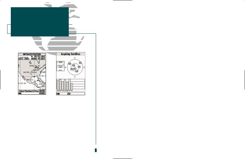
2.Press the Jkey again to return to the previous page. The ‘select initialization’ window will appear, with the ‘select from map’ option highlighted.
3.Press Tto initialize the receiver from the built-in worldwide map.
GETTING STARTED
Initialization
A |
B |
A.The Welcome Page will be displayed while the unit performs a self-test.
B.Confirm the mariner’s warning before starting navigation. Remember that the electronic chart is designed to supplement the local government charts, not replace them.
1
GETTING STARTED
Initialization
A |
B |
A.Use the arrow keypad to move the cursor to a location close to your present position.
B.Hollow signal strength bars will appear on the Status Page while the receiver collects satellite data.
2
Initializing the Receiver (con’t.)
The Map Page will appear, prompting you to select your approximate present position with the map cursor.
1.Use the Rkeypad to move the map cursor to a location close to your present position. If you have difficulty identifying your exact position, use the Ikey to zoom to a lower map scale.
2.Press Tto confirm your selection.
The sounder will now begin searching for the appropriate satellites for your present position and should acquire a fix in approximately one minute. While the receiver searches for satellites, a flashing satellite symbol will appear at the left-hand side of the status bar located at the bottom of the screen. The status bar is used to monitor satellite signal reception and activated alarms, it also shows the digital depth on a continual basis.
A signal strength bar for each satellite in view will appear on the lower half of the page, with the appropriate satellite number under each bar. The progress of satellite acquisition is shown in three stages:
•No signal strength bars: The receiver is looking for satellites.
•Hollow signal strength bars: The receiver has found satellites and is collecting data.
•Solid signal strength bars: The receiver has collected the necessary satellite data and the sounder is ready to use.
Once the receiver has collected information from at least three satellites, the satellite symbol on the status bar will stop flashing.
Getting Started Tour
The GARMIN GPSMAP 235 Sounder is a powerful electronic navigation and depth sounding system that provides detailed chart coverage and convenient control of many advanced features right from the screen display. This tour is designed to take you through the basic pages and functions of the system using the simulator mode. Once you’re familiar with the main pages and features of the unit, refer to the reference section for instructions on performing specific tasks and functions.
The Getting Started Tour assumes that the receiver has been properly installed and initialized, and you have not changed any of the default unit settings. If you have changed any settings (position formats, units of measure, etc.), the descriptions and pictures in the tour may not match your configuration.
To turn the sounder on:
1.Press and hold the Pkey until the power tone sounds. The welcome page will appear while the unit conducts a self test.
2.Once the self test is complete, press the Tkey to acknowledge the mariner’s warning.
The satellite status page will appear as the receiver begins acquiring satellites. From the status page, you can adjust the screen contrast and backlighting.
To adjust the screen contrast:
1.To increase the screen contrast, press the right arrow of the Rkeypad.
2.To decrease the screen contrast, press the left arrow of the Rkeypad.
3.Press the Tkey to finish.
The sounder’s three-level screen backlighting feature is controlled with Pkey, and can be adjusted at any time from any page.
To turn on and adjust the backlighting:
1. Press the Prepeatedly until the backlighting is at the desired level (off, 1, 2, or 3).
GETTING STARTED
Power On/Screen Contrast
A |
B |
A.The screen contrast may be adjusted from the Status Page by pressing the ARROW KEYPAD. Press EDIT/ENTER to confirm changes.
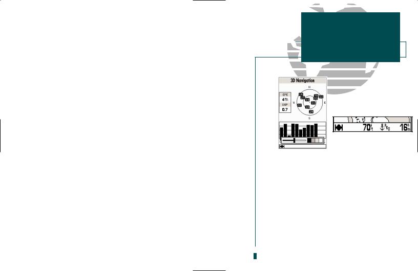
B.The status bar at the bottom of the screen is displayed at all times. It continuously indicates current depth and displays symbols which identify what mode the unit is in, satellite signal presence, and which alarms (if any) have been triggered. The current scale will also be displayed if you are viewing the navigation or Map Page, or if you are using the sounder zoom feature. When you are viewing
the Sounder Page, it will show the transducer |
3 |
|
frequency. |
||
|

GETTING STARTED
Status Page/Simulator Mode
A B
A.To start the simulator, confirm the simulator warning. Do not use simulation for actual navigation or to determine actual water depth.
B.Whenever the sounder is in simulator mode, a ‘Setup Simulator?’ option will appear on the options menu for each page. An ‘Exit Simulator?’ option will also appear on the Status Page options menu.
4
Status Page
Status Field 
Satellite
Horizontal Accuracy 
 Sky View
Dilution of Precision 
Signal Strength
Indicators
Status Bar |
Water Depth |
The Status Page provides a visual reference of satellite acquisition and receiver status, with a signal strength bar graph and a satellite sky view in the center of the page. Each page of the sounder features an options menu, which gives you access to other functions and features that relate to the specific page you are viewing. To get a feel for how the this works, let’s put the sounder into simulator mode.
To put the sounder in simulator mode:
1.From the Status Page, press the Okey. The options menu will appear, displaying functions and features for the Status Page.
2.Use the UP or DOWN arrow of the Rkeypad to highlight the ‘Start Simulator?’ option and press T.
3.Press the Tkey to confirm the simulator warning. Once the simulator has been started, the status field at the top of the page will display ‘Simulating Navigation.’
Now you’re ready to continue the rest of the tour. All the waypoint and route planning done in simulator mode will still be retained in memory for future use.

The satellite Status Page is one of five main pages used in the sounder. All five pages are linked together in a simple chain, which allows you to scroll through the pages in either direction using the Jand Qkeys. To continue the tour, let’s move on to the next page, the position page.
To scroll to the next page in sequence:
1. Press the Jkey.
Position Page
The Position Page shows your position, direction of travel, and speed. The compass tape at the top of the page indicates the direction you’re moving. The four user-selectable data fields below the compass tape show your current course and speed over ground, along with a resettable trip odometer and depth display. Your current latitude and longitude, along with a 12/24-hour clock, appear at the bottom of the page.
Now that you’ve seen how the status and position pages can be used to monitor satellite acquisition and your present position, let’s take a minute to learn how to mark and store our present position as a waypoint. Since we’re in simulator mode, the present position displayed will be the last position calculated by the receiver, which should be the spot where you initialized the unit. Marking a position will also give you an opportunity to see how the sounder’s arrow keypad (R) and T key are used for data entry.
GETTING STARTED
Page Sequence/Position Page
Compass
Tape
Data
Fields
Position
Coordinates
Time
of Day
Status Bar
5

GETTING STARTED
UsingMarkingthe aGOTOPositionKey
A |
B |
A.The mark position page will automatically assign a default, three-digit name for each waypoint, which can be changed at any time to an alphanumeric name containing up to six-characters.
B.A complete set of waypoint symbols allows you to mark inland and offshore waypoints with a custom symbol for fast waypoint recognition.
6
Marking a Position
To mark your present position:
1.Press the Mkey. The mark position page will appear, with a default three-digit waypoint name, symbol, position, and depth.
2.Use the Rkeypad to highlight the waypoint name field (001) and press T.
3.Press the LEFT ARROW of the Rkeypad to clear the name field.
4.Use the Rkeypad to enter the name ‘DOCK,’ using the UP and DOWN arrows to select each letter, and the RIGHT arrow key to advance to the next character position. If you make a mistake and select an incorrect character, simply use the LEFT arrow key of the Rkeypad to backspace the cursor and correct the entry.
5.Press Tto confirm the name.
6.The field highlight will advance to the symbol field. Press Tto access the waypoint
symbol page.
7.Use the Rkeypad to highlight the ANCHOR symbol.
8.Press Tto confirm the symbol.
9.Press Tagain to confirm the ‘DONE?’ prompt and save the waypoint.
The DOCK waypoint is now stored in memory. Waypoints can also be created graphically from the map display, by manually entering position coordinates, or as underwater waypoints from the Sounder Page. Each of these techniques is described in the reference section of the manual or in the quick reference guide. To continue our tour, let’s move on to the Sounder Page.
1. Press the Jkey to access the Sounder Page.

Sounder Page
Data Field |
Range Mode |
Fish Arch
Thermocline
Whiteline 
 Transducer Frequency
The Sounder Page lets you use the GPSMAP 235 as a fishfinder. The top of the screen contains any of seven selectable data field options, while the middle of the page contains a right-to-left moving sonar image of the water beneath your boat. (Note: Items appear on the screen as they pass under your transducer. Those objects appearing on the right side of the screen are closer to you than those on the left.) Fish are displayed as a darkened arch or a fish symbol in three different sizes. Thermoclines (layers of water separating warmer water from cooler water ) are shown as shades of gray.
The area of strongest sonar return (or “whiteline”) is displayed as a light gray band. Typically, the bottom will be the primary source of the whiteline. A thin whiteline indicates a softer bottom while a thick whiteline shows a harder bottom. A black line is used to show the point where water meets the whiteline. This black line will follow the bottom contour, along with any significant objects lying on the bottom. Along the right side of the screen is an adjustable scale which reflects the depth of the area being displayed. The status bar at the bottom of the page displays satellite signal status, digital depth, and any triggered alarms. More on the Sounder Page may be found on pages 24-38.
GETTING STARTED
Sounder Page
A |
B |
A.When adjusted correctly, the bottom is outlined by the whiteline. To adjust the whiteline, see page 30.
B.Pause the screen by pressing the EDIT/ENTER key at any time. To continue screen movement, press EDIT/ENTER again. Pause the screen to allow more time to examine the screen display and when using the underwater waypoint feature.
7

GETTING STARTED
Range Modes
A |
B |
A.When switching between auto and manual modes, the range scale will be highlighted.
B.The depth of the waypoint is captured with the underwater waypoint feature.
8
Range Modes
The unit uses three range modes on the Sounder Page: auto, manual, and window. Auto mode displays the most information possible while continuously showing the bottom. Manual mode lets you select the displayed depth. Window mode allows you to define a starting depth and length of the range window,. but must be started from the sounder options menu (see page 31).
To switch from auto to manual mode:
1.Press the Rkeypad up or down until the desired depth range is displayed on the depth scale at the right side of the page. Press Tto confirm the selected range.
To switch from manual to auto mode:
1.Press the Rup or down and hold it until you hear a repeated beep. ‘Auto’ will be displayed in the function field at the top-right corner of the page. Press T.
Underwater Waypoints
The underwater waypoint feature marks a waypoint’s position and its depth. Marking an underwater waypoint makes it easier to find and use an object for a future fishing location reference point.
To mark an underwater waypoint:
1.Press Tto pause the screen movement.
2.Use the Rkeypad to move the cursor onto the target you want to mark. A data field will appear with the cursor’s depth and bearing and distance from your current position.
3.Press T. A waypoint page will appear with the waypoint’s coordinates, default three-digit name, and depth.
4.Enter any waypoint information such as name, comment, etc., and press T. When finished, press Qor T.
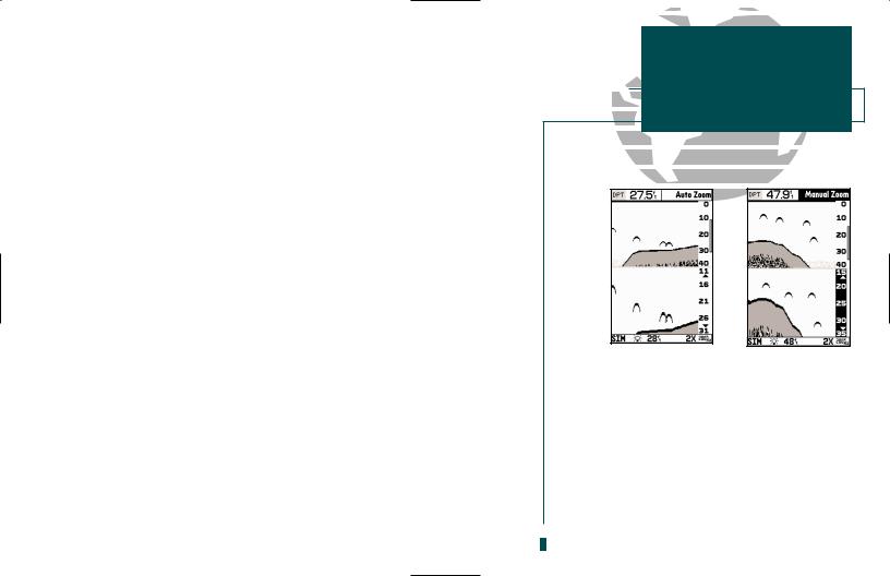
Zoom Feature
The zoom feature allows you to view a smaller portion of the complete range in greater detail.
The zoom feature operates in auto or manual mode. Auto zoom will follow the bottom contour while manual zoom will display the selected depth. For more on the zoom feature, see pages 26-27.
To use the zoom feature:
1.While viewing the Sounder Page, press I. The zoomed part of the display (always the bottom part) shows you twice the detail of the original display at half the depth.
2.Pressing Ia second time shows you twice the detail of the original at half the depth in one screen.
3.Pressing Ia third time shows you four times the detail in the zoomed part of the screen at a quarter of the original depth.
4.Pressing Ia fourth time shows you four times the detail in the zoomed part of the screen at a quarter of the original depth in one screen.
Note: When dual frequency is selected, there is no split zoom with a full range over a zoomed window. Both the 50 kHz and the 200 kHz will zoom together, regardless of which is on top or bottom.
To turn the zoom feature off, press Huntil the original scale picture appears and a triple beep sounds.
Let’s continue the Getting Started Tour with the Map Page.
1. Press J.
GETTING STARTED
Zoom Feature
A |
B |
A.Use the zoom window to view a smaller portion of the complete range in greater detail.
B.Moving the zoom window allows you to quickly view any spot between the surface and the bottom. See page 27 for directions on moving the zoom window.
9
GETTING STARTED
Map Page
A |
B |
A.The map/sounder split screen displays cartography and sounder information at the same time. The split screen only functions as a map page, and any changes to the sounder display must be made from the Sounder Page. Use the QUIT or PAGE key to quickly switch between the map split-screen and the Sounder Page. See page 28 for split screen operation information.
B.The Map Page can also be configured to display additional data fields and a graphic course devia-
tion scale or compass. See page 46 for more on map 10 options.
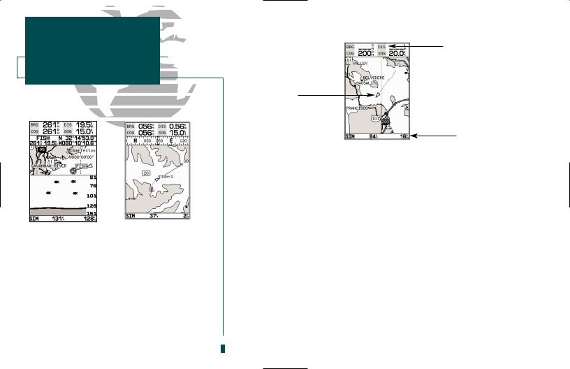
Map Page
Data
Fields
Boat
Symbol
Map
Scale
The Map Page combines digital chartplotting with a user-selectable display of navigation data, and a built-in worldwide database. It will also be the page you use most to create and edit waypoints and routes. Before we take off on a practice route, let’s take a brief look at its various features and displays.
The map display, located in the middle of the Map Page, shows your boat as a triangular marker. Geographic names, markers and buoys that are provided by the G-chart cartridge you’re using are also shown. It also displays your track, routes and nearby waypoints. An on screen cursor lets you pan to other map areas, determine the range and bearing to a position, and perform various waypoint and route functions.
The data window, located at the top of the page, provides a user-selectable display of various navigation data, including course, speed over ground, and bearing and distance to the cursor or a particular waypoint. The status bar, located at the bottom of the page, displays the current map scale setting, as well as the status information described on page 3.
Using the Map Cursor
The cursor is an important tool that can be used to pan to other map locations, mark and edit waypoints and routes, and review position data of on-screen navaids and waypoints. To get a feel for using the Map Page and cursor, try the following exercise:
1.Use the Hkey to set the map scale to the 64 nm setting. Your boat should be near the center of the map.
2.Use the DOWN arrow of the Rkeypad to move the cursor down to the first lat/lon grid south of your boat’s position.
3.Using the Rkeypad to move the cursor, try following the outline of the lat/lon grid closest to your boat. Notice how another data field appears at the top of the page, showing the bearing and distance from your boat to the cursor, along with the lat/lon of the cursor.
4.Press the Qkey to remove the cursor and recenter your boat on the map display.
As you become more familiar with the cursor, you’ll see that the map display actively scrolls or ‘pans,’ letting you explore areas in and outside of your current G-chart coverage, and create waypoints and routes. Wherever you move the cursor, you’ll always be just one keystroke away from returning the map to your present position by pressing Q.
Now that you have a feel for how the cursor works, let’s move on and see how the sounder works on the water. To help you practice using the Map Page and other features, we’ve stored a practice route in the receiver’s memory so that you can see exactly what you’ll experience when you’re navigating with your new GPS chartplotter.
GETTING STARTED
Map Cursor
A B
A. Whenever the cursor is active, the bearing and distance of the cursor from your present position will appear in a pop-up data window. To remove the cursor and re-center your vessel on the map, press the QUIT key.
B. To select an on-screen waypoint, simply move the cursor over the desired waypoint. The waypoint/navaid name and position, along with the bearing and distance from your present position, will be displayed. Underwater waypoints
are also shown on the map.
11

GETTING STARTED
Using the GOTO Feature
A B
A.Pressing GOTO once displays a list of all waypoints stored in memory. To pick a destination, select the desired waypoint and press EDIT/ENTER.
B.The GOTO options menu allows you to start a TracBack route back home, select a destination from the nearest waypoints list, or select a route to navigate.
12
Going to a Destination
GPS is all about marking positions as waypoints and navigating to them using the receiver’s steering guidance and map displays. We’ve already seen how to use the Mkey to store our present position, so it’s time to move on to the fun part— going to a destination. The Gkey, located on the left side of the keypad above the Qkey, is the primary tool used to select a destination waypoint or a route to navigate. The Gkey can be used in three primary ways:
•Pressing Gonce displays a list of all waypoints in memory, from which you can select a single destination waypoint.
•Pressing G followed by the O key provides a list of GOTO options that lets you start a TracBack route, select a destination waypoint from the nearest waypoints list, select a stored route to navigate, or cancel the current GOTO destination.
•Pressing Gtwice allows you to graphically select an on-screen waypoint, navaid or cursor position as a destination directly from the map display.
For our simulated trip, we’re going to select the pre-programmed tour route. (Don’t delete the tour route. Once it’s deleted, it can’t be retrieved for further practice.) The tour route will automatically place our vessel at the first route waypoint. Navigating the tour route will also give us an idea of how the Okey is used to provide context-sensitive options and functions. Let’s try it by activating the practice tour route stored in memory for navigation:
1.Press G. The waypoint list page will appear. (If we were selecting a single waypoint to navigate to rather than a route, we would highlight the waypoint and press T.)
2.Press Oto display the options menu available for the GOTO function.
3.Use the Rkeypad to highlight the ‘Select Route?’ option. Press Tto confirm.
4.The select route page will appear, with the ‘GPSMAP TOUR’ route highlighted.
5.Press T. The Map Page will reappear and display five waypoints chained together in a simple route, with your boat at the first route waypoint.
Going to a Destination (con’t.)
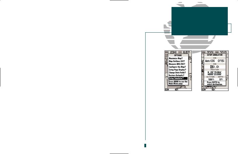
A data field at the top of the page will now display the bearing and distance to the second route waypoint. To get started, let’s enter a speed for our vessel, which we can do from the ‘Setup Simulator?’ listing on the map options menu. The setup simulator page is available from any page in the main page sequence.
To enter a boat speed:
1.Press the Okey to display the map options menu.
2.Use the Rkeypad to select the ‘Setup Simulator?’ option and press T.
3.Once the setup simulator page appears, press Tto access the SOG field.
4.Use the Rkeypad to enter a speed of 60 knots.
5.Press Tto finish, and Jto return to the map display.
Once a speed has been entered, you’ll notice that the map will begin to move slowly, keeping your boat centered on the display. To get a better view of what’s going on, zoom in to a closer map scale.
1. Press the Hkey to select the 16 nm scale.
You’ll now have a clearer picture of the route we are navigating, along with an outline-only presentation of the surrounding shoreline. Because the usable range of the built-in database is only valid to 64 nm scale (32nm in the U.S.), we no longer have full cartography available.
Keep in mind that whenever you do exceed the usable range of the built-in database or the G-chart cartridge in use, the range field will display ‘OVR ZM’ or ‘NO MAP’ to indicate that you should exercise extreme caution using the cartography data. See pages 42 and 85 for more information on map scales and using G- chart detailed cartography.
GETTING STARTED
Simulator Setup
A |
B |
A.To enter a boat speed or define the simulated course, highlight the ‘Setup Simulator?’ option and press EDIT/ENTER.
B.Enter a boat speed of 60 knots to begin the tour. Sixty knots will allow you to complete the Getting Started tour in approximately 10-15 minutes.
13

GETTING STARTED
Reviewing and Creating
Waypoints on the Map
A B
A.Waypoints can be created from the map display by moving the cursor to the desired position and pressing the EDIT/ENTER key.
B.The create new waypoint page will automatically assign the next available three-digit number as the default waypoint name. If you are creating a waypoint at an on-screen navaid, the navaid icon and name will be used as the default symbol and comment.
14
Going to a Destination (con’t.)
Now that we’ve zoomed in a little closer to our route, we can pan ahead of our vessel with the cursor to review and create on-screen waypoints and navaids. Try moving the cursor to select the ‘TOUR3’ waypoint— just use the R keypad to move the cursor as close as possible to the waypoint. (To move the cursor in small increments, try a series of short key presses.)
Once the cursor is over the TOUR3 waypoint, you’ll notice that the waypoint symbol and name will become highlighted. The data field at the top of the page will display the waypoint name, the range and bearing from your present position, and the coordinates for the waypoint.
To review the waypoint page for a selected waypoint:
1.Press the Tkey.
2.To return to the Map Page, press Tagain.
The cursor can also be used to create new waypoints right from the map display.
To create a new waypoint using the cursor:
1.Use the Rkeypad to move the cursor as close as possible to the following position: N 35º 02.129’; W 076º 26.106’ (Use the data window to verify the cursor position.)
2.Press the Tkey to capture the cursor position.
3.Use the Rkey to highlight the waypoint symbol field.
4.Press Tto access the symbol page.
5.Press the DOWN arrow of the Rkeypad twice to select the wreck symbol.
6.Press Tto confirm, and Tagain to finish.
Now that we’re navigating to an actual destination, let’s move on to the next page of the sounder, the Navigation Page:
1. Press the Jkey.
Navigation Page
Data
Fields
Compass Tape
Graphic
Highway 
Pointer to
Waypoint
CDI
Scale
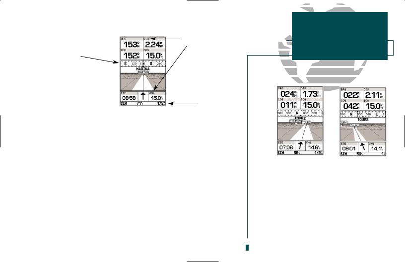
The Navigation Page provides graphic steering guidance to your destination. The bearing (BRG) and distance (DIS) to the destination, with your current course (COG) and speed over ground (SOG), are displayed at the top of the page, along with a compass tape to indicate your cardinal heading. The estimated time enroute (ETE) and velocity made good (VMG, or the rate you are closing in on your destination) are displayed at the bottom of the page.
As you head toward the destination, the middle section of the page gives you visual guidance to your waypoint on a graphic highway, which displays the route and nearby waypoints on screen. The moving arrow below the highway always points to the destination waypoint relative to the direction you’re moving.
The line down the center of the highway represents your desired track, while the bottom of the page provides a graphic indication of your crosstrack error (the distance and direction you are off course) according to the scale at the bottom right of the page.
In simulator mode, you can adjust your speed and course from the Navigation Page using the Rkeypad. As you head toward each waypoint in the tour route, try adjusting your boat speed and course to get a feel for how the highway works.
GETTING STARTED
Overview
A |
B |
A.In this example, our boat is off course to the left by about 1/8th of a mile (the base of the highway map is equal to the scale selected at the bottom right of the page). To get back on course, steer right.
B.In this example, our boat is off course to the right. To get back on course, steer left. A digital readout of your exact crosstrack error can be displayed in any of the six data fields (see page 47).
15

GETTING STARTED
Using the Navigation Page
A B
A.To reset the simulator to steer the desired course automatically, select the ‘Auto COG’ setting from the options menu.
B.The highway scale can be set to a 1/4-, 1/2-, 1-, 2-, or 4-nm/mi/km range with the ZOOM keys.
16
Navigation Page (con’t.)
To adjust the simulated boat speed:
1.Press the UP arrow of the Rkeypad to increase the speed in 5 knot/kph/mph increments. Press the DOWN arrow to decrease the speed in the same increments.
To steer the boat:
1. Press the LEFT or RIGHT arrows of the Rkeypad.
Notice that as you get off course, the highway and waypoint pointer move to give you graphic guidance to get back on course. The scale in the lower right corner of the page represents the total distance (or the width) of the base of the highway display. The default graphic highway setting is 1/4 nm, but can be set for a 1/2-, 1-, 2- or 4-nm range.
To change the highway scale display:
1.Press the Hor Ikey in either direction (up to increase, down to decrease the scale).
The Navigation Page data fields can also be configured to display any of eight different navigation information categories. Let’s change the ETE field to ETA (estimated time of arrival).
To change a data field:
1.Press the Okey to display the position page options.
2.Highlight the ‘Change Data Fields?’ option and press T. The field highlight will now appear in the top-left data field (the COG field).
3.Use the Rkeypad to move the field highlight to the ETE field and press T. Highlight the ‘ETA’ option and press T, and press Qto finish.
Now that you’ve seen the five main pages, let’s look at the active route page, which appears in the main page sequence whenever you are navigating a route:
1. Press J.

Active Route Page
The active route page shows each waypoint of the active route in sequence, with the waypoint name, distance and estimated time enroute to each waypoint displayed. As you navigate the route, the active route list will be automatically updated, indicating the next destination waypoint. The active route page also provides quick access to many route activation, editing and copying functions you’ll use most often, like inverting and deactivating the active route. Let’s go ahead and deactivate the active route.
To deactivate the active route and stop navigation:
1.Press the Okey.
2.Highlight the ‘Deactivate Route?’ option.
3.Press Tto confirm.
To reset the boat speed to zero:
1.Press the Okey.
2.Highlight the ‘Setup Simulator?’ option.
3.Press T.
4.Press Tto access the SOG field.
5.Press the LEFT arrow of the Rkeypad to clear the speed entry.
6.Press T.
As you’ve seen, the primary pages provide status, position, fishfinding, navigation and map information. The tour’s last page is the main menu page, which allows access to the sounder’s waypoint, route and planning functions, as well as various operational and navigation setup features. The main menu is available from any page, and is accessed through the Okey.
To access the main menu page:
1. Press the Okey twice.
GETTING STARTED
Active Route Page
A |
B |
A.To stop navigating the active route, select the ‘Deactivate Route?’ option and press EDIT/ENTER.
B.Use the left arrow key to clear the SOG field and press EDIT/ENTER to confirm.
17
GETTING STARTED
Main Menu and Power Off
A B
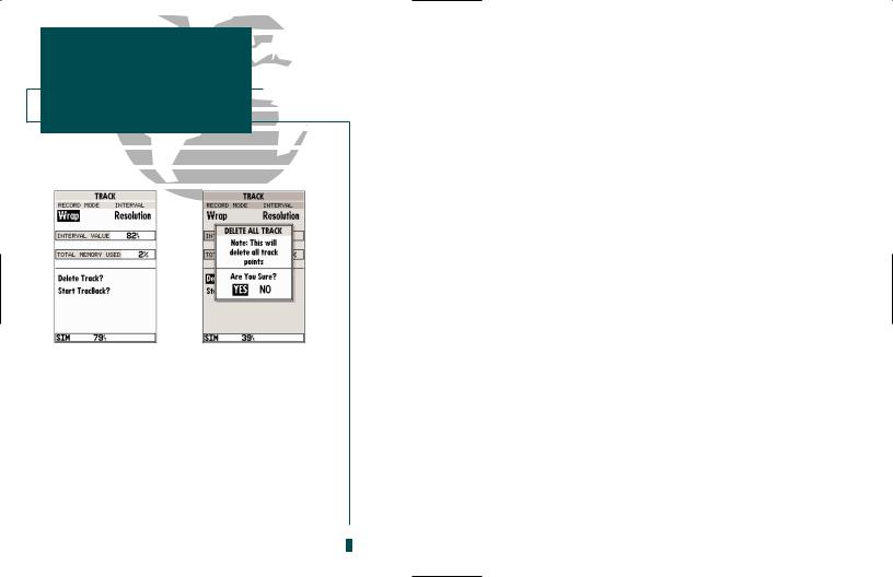
A.The sounder’s track page lets you clear the track log and start a TracBack route.
B.To delete the track log, confirm the warning page by highlighting the ‘YES’ prompt and pressing EDIT/ENTER.
18
Main Menu Page
The main menu page’s eleven submenus are divided into categories by function. You can select a particular submenu by simply highlighting the desired option and pressing T. To get a feel for how the main menu page works, let’s clear out the track log we’ve created during our simulated tour. Clearing the track log will ensure that you have a clean slate once you start navigating in your home waters.
To select the track submenu:
1. Highlight the ‘Track’ menu option and press T.
The track log page allows you to specify whether to record a track plot and define how it is recorded. It also provides both an indicator of the total memory used and the individual functions to clear the track log and start a TracBack route.
To delete the track log:
1.Highlight the ‘Delete Track’ option and press T. A confirmation page will appear.
2.Highlight the ‘Yes’ prompt and press Tto confirm.
3.Press Jto return to the main page sequence.
Congratulations! You’ve now gone through the basic operation of the GARMIN GPSMAP 235 Sounder. Your new digital chartplotter is a powerful tool with many advanced features not covered in the Getting Started tour. For detailed instructions on using these features or performing a specific task, please refer to the quick reference guide or the appropriate reference section of this manual.
To turn the sounder off:
1. Press the Pkey.
The next section of the manual describes the pages and features of the GPSMAP 235 Sounder in detail. If you are unable to locate a specific option or feature, please refer to the index on pages 106-108.

Status Page
Status Field 
Satellite
Horizontal Accuracy |
Sky View |
|
|
Dilution of Precision |
|
|
Signal Strength |
|
Indicators |
Status Bar |
|
The Status Page provides a visual reference of various receiver functions, including current satellite coverage, receiver operating mode and current receiver accuracy. The status information will give you an idea of what the receiver is doing at any given moment.
The sky view and signal strength bars give you an indication of what satellites are visible to the receiver and whether or not they are being tracked. The signal strength is shown on a bar graph for each satellite, with the satellite number below. When a satellite is visible but not being tracked, the strength bar will not be shown and the sky view indicator will not be highlighted.
The sky view shows a bird’s-eye view of the position of each satellite relative to the receiver’s last known position. The outer circle represents the horizon (track up), the inner circle 45º above the horizon, and the center point a position directly overhead. Use the sky view to determine if there are obstructions shading your reception of GPS signals.
STATUS PAGE |
SECTION |
|
1 |
||
Overview |
||
|
A |
B |
A.Whenever the sounder is searching for satellites, no signal strength bars will appear.
B.Once the receiver has found the satellite(s) indicated, a hollow signal strength bar will appear. After satellite data has been collected, the signal strength bars will become solid.
19

SECTION |
STATUS PAGE |
|
1 |
||
Receiver Status |
A B
A.The status bar at the bottom of the page displays important status, alarm and map scale information. It also provides on-screen user and message prompts.
B.The status bar will display an anchor symbol or ‘PRX’ icon whenever the anchor drag alarm or proximity alarm has been triggered.
20
Receiver Status, EPE and DOP
Receiver status is displayed at the top of the page, with the current estimated position error (EPE) and dilution of precision (DOP) to the left of the sky view. DOP is an indication of satellite geometry quality measured on a scale of one to ten (lowest numbers the best, highest numbers the poorest). EPE uses DOP and other factors to calculate a horizontal position error in feet or meters. The status field will show one of the following conditions:
•Searching the Sky: The receiver is looking for satellites.
•AutoLocate: The receiver is is looking for any satellite whose almanac has been collected. The autolocate process can take up to five minutes.
•Acquiring Satellites: The receiver is looking for and collecting data from satellites visible at its last known or initialized position, but has not collected enough data to calculate a fix.
•2D Navigation: At least three satellites with good geometry have been acquired and a two dimensional position fix (latitude and longitude) is being calculated. ‘2D Differential Navigation’ will appear when you are receiving DGPS corrections in 2D mode.
•3D Navigation: At least four satellites with good geometry have been acquired and your position is now being calculated in latitude, longitude and altitude. ‘3D Differential Navigation’ will appear when you are receiving DGPS corrections in 3D mode.
•Poor GPS Coverage: The receiver is no longer tracking enough satellites for a 2D or 3D fix.
•Receiver Not Usable: The receiver is unusable, possibly due to incorrect initialization or abnormal satellite conditions. Turn the unit off and back on to reset.
•Simulating Navigation: The receiver is in simulator mode.
 Loading...