


500W Series
Instructions for Continued Airworthiness Bell 407
Reg. No.____________ |
S/N_______________ |
Dwg. Number:
190-01226-13 Rev. 3
Garmin International, Inc.
1200 E. 151st Street
Olathe, Kansas 66062 USA
|
|
Record of Revision |
|
|
|
Rev. |
Date |
Description of Change |
1 |
04/09/15 |
Initial Release |
206/18/15 Updated Airworthiness Limitations section
302/08/17 Updated troubleshooting table section to add GDL 88H and GTX 3X5

Company Proprietary Information
This drawing and the specifications contained herein are the property of Garmin International or its subsidiaries and may not be reproduced or used in whole or in part as the basis for manufacture or sale of products without written permission.
Copyright 2017 Garmin Ltd. or its subsidiaries. All rights reserved.
Garmin International, Inc.
1200 E. 151st Street
Olathe, Kansas 66062 U.S.A.
500W Series |
190-01226-13 Rev. 3 |
Instructions for Continued Airworthiness Bell 407 |
Page 2 of 26 |
1. |
INTRODUCTION................................................................................................................... |
4 |
|
|
1.1 |
Purpose................................................................................................................. |
4 |
|
1.2 |
Scope.................................................................................................................... |
4 |
|
1.3 |
Document Control................................................................................................. |
4 |
|
1.4 |
Permission to Use Certain Documents................................................................. |
4 |
|
1.5 |
Definitions ............................................................................................................. |
4 |
2. INSTRUCTIONS FOR CONTINUED AIRWORTHINESS .................................................... |
5 |
||
|
2.1 |
Introduction ........................................................................................................... |
5 |
|
2.2 |
Description of Alteration........................................................................................ |
6 |
|
2.3 |
Control, Operating Information ............................................................................. |
11 |
|
2.4 |
Servicing Information ............................................................................................ |
11 |
|
2.5 |
Periodic Maintenance Instructions........................................................................ |
12 |
|
2.6 |
Troubleshooting Information................................................................................. |
14 |
|
2.7 |
Removal and Installation Information ................................................................... |
23 |
|
2.8 |
Diagrams............................................................................................................... |
24 |
|
2.9 |
Special Inspection Requirements ......................................................................... |
25 |
|
2.10 |
Application of Protective Treatments.................................................................... |
25 |
|
2.11 |
Data Relative to Structural Fasteners................................................................... |
25 |
|
2.12 |
Special Tools ........................................................................................................ |
25 |
|
2.13 |
Additional Instructions........................................................................................... |
25 |
|
2.14 |
Overhaul Period.................................................................................................... |
25 |
|
2.15 |
ICA Revision and Distribution............................................................................... |
26 |
|
2.16 |
Assistance............................................................................................................. |
26 |
|
2.17 |
Implementation and Record Keeping ................................................................... |
26 |
3. |
AIRWORTHINESS LIMITATIONS ........................................................................................ |
26 |
|
500W Series |
190-01226-13 Rev. 3 |
Instructions for Continued Airworthiness Bell 407 |
Page 3 of 26 |
1. INTRODUCTION
1.1Purpose
This document is designed for use by the installing agency of the Garmin Model 500W series GPS/WAAS Nav/Com as Instructions for Continued Airworthiness in response to Title 14 CFR Part 27.1529, Part 27 Appendix A. This ICA includes information required by the operator to adequately maintain the Garmin 500W unit and additional equipment installed under STC SR02080SE.
1.2Scope
This document identifies the Instruction for Continued Airworthiness for the Bell 407 series rotorcraft modified by the installation of the Garmin Models 500W series GPS/WAAS Nav/Com unit and additional equipment under STC SR02080SE.
1.3Document Control
This document shall be released, archived, and controlled in accordance with the Garmin document control system. When this document is revised, refer to Section 2.15 for information on how to gain FAA acceptance or approval and how to notify customers of changes.
1.4Permission to Use Certain Documents
Permission is granted to any corporation or person applying for approval of a Garmin Model 500W series to use and reference appropriate STC documents to accomplish the Instructions for Continued Airworthiness and show compliance with STC engineering data. This permission does not construe suitability of the documents. It is the responsibility of the applicant to determine the suitability of the documents for the ICA.
1.5Definitions
The following terminology is used within this document:
1)ACO: Aircraft Certification Office
2)AEG: Aircraft Evaluation Group
3)CFR: Code of Federal Regulations
4)FAA: Federal Aviation Administration
5)ICA: Instructions for Continued Airworthiness
6)PMI: Principle Maintenance Inspector
7)STC: Supplemental Type Certificate
500W Series |
190-01226-13 Rev. 3 |
Instructions for Continued Airworthiness Bell 407 |
Page 4 of 26 |
2. INSTRUCTIONS FOR CONTINUED AIRWORTHINESS
2.1 Introduction
Content, Scope, Purpose and Arrangement: |
This document identifies the Instructions for |
|
Continued Airworthiness for the modification of the |
|
rotorcraft by installation of a 500W series |
|
GPS/WAAS Nav/Com unit under the Garmin Bell |
|
400W/500W HTAWS STC SR02080SE. |
Applicability: |
Applies to Bell model 407 rotorcraft altered by |
|
installation of a 500W series GPS/WAAS Nav/Com |
|
unit under the Garmin Bell 400W/500W HTAWS |
|
STC SR02080SE. |
Definition of Abbreviations: |
See Section 1.5 |
Precautions: |
None |
Units of measurement: |
None |
Referenced publications: |
Garmin 005-00610-03 Rev. 2 “Equipment List |
|
400W/500W Series Installation Bell 206 and 407 |
|
STC” or later FAA Approved Revisions |
|
Garmin 190-01226-01 Rev. 3 “500W Series |
|
Rotorcraft STC Installation Manual” or later FAA |
|
Approved Revisions |
Additional Maintenance Data: |
Garmin 190-01226-10 Rev. 1 “400W/500W Series |
|
Installation Bell 407” or later FAA Approved |
|
Revisions |
Retention: |
This document, or the information contained within, |
|
will be included in the rotorcraft’s permanent |
|
records. |
500W Series |
190-01226-13 Rev. 3 |
Instructions for Continued Airworthiness Bell 407 |
Page 5 of 26 |

2.2Description of Alteration
This STC upgrades existing avionics for the Bell 407 rotorcraft as summarized below.
The Garmin Model 500W Series GPS/WAAS Nav/Com is a 6 ¼ inch wide unit mounted in the avionics console of the Bell 407. The 500W Series units combine a large number of easily accessible controls to use the color multi-function display, Nav and Com transceiver, GPS/WAAS navigator in a single unit. A GPS/WAAS antenna is installed on the top of the Bell 407 forward engine cowl. A monitored avionics cooling fan is installed in the instrument panel support with a fan fail fault annunciation located in the existing caution and warning annunciator panel.
|
1 |
(1) |
8 |
013 00103 00 |
GFC 3XX 3 PORT COOLING FAN |
|
|
1 |
(1) |
|
011 00351 00 |
CONNECTOR KIT GNS 430W GNS 430AW |
|
|
|
(1) |
7 |
011 00351 01 |
CONNECTOR KIT GNC 420W GNC 420AW |
|
|
|
(1) |
|
011 00351 03 |
CONNECTOR KIT GPS 400W GPS 500W |
|
|
|
(1) |
6 |
011 00676 00 |
BACKPLATE SUB ASSEMBLY 400W SERIES NAVIGATOR |
|
|
1 |
|
5 |
011 00671 00 |
BACKPLATE SUB ASSEMBLY 500W SERIES NAVIGATOR |
|
|
1 |
|
4 |
115 00345 00 |
MOUNTING RACK 500W SERIES NAVIAGATOR |
|
|
|
1 |
3 |
115 00243 00 |
MOUNTING RACK 400W SERIES NAVIAGATOR |
|
|
|
|
|
011 01061 XX |
GNS 430AW NAVIGATOR |
|
|
|
|
|
011 01060 XX |
GNS 430W NAVIGATOR |
|
|
|
(1) |
2 |
011 01059 XX |
GNC 420AW NAVIGATOR |
|
|
|
|
|
011 01058 XX |
GNC 420W NAVIGATOR |
|
|
|
|
|
011 01057 XX |
GPS 400W NAVIGATOR |
|
|
|
|
|
011 01066 XX |
GNS 530AW NAVIGATOR |
|
|
1 |
|
1 |
011 01064 XX |
GNS 530W NAVIGATOR |
|
|
|
|
|
011 01062 XX |
GPS 500W NAVIGATOR |
|
|
5XX |
4XX |
ITEM NO. |
PART NUMBER |
DESCRIPTION |
|
|
QTY. |
|
||||
|
|
|
|
|
||
|
|
|
|
|
|
|
|
500W Series |
|
|
190-01226-13 Rev. 3 |
||
|
Instructions for Continued Airworthiness Bell 407 |
Page 6 of 26 |
||||
This STC also provides the data for installation of optional HTAWS annunciators and optional cyclic stick switches for remote control of COM and HTAWS functions.
The 500W Series unit can interface to the Garmin G500H system GDU 620 PFD/MFD for display of navigation information and HTAWS annunciation.
Rotorcraft modified under this STC are restricted to VFR only, including rotorcraft that may not have previously been restricted to VFR. To clarify this operation limitation, a placard with the text, “APPROVED FOR DAY/NIGHT VFR” is required to be in the pilot’s view.
The installed equipment is connected to an avionics bus that receives power as soon as the battery and avionics master switches are turned on. Circuit breakers are installed in the panel located in existing overhead console, as shown below (Note: circuit breakers for dual navigator installation are shown).
500W Series |
190-01226-13 Rev. 3 |
Instructions for Continued Airworthiness Bell 407 |
Page 7 of 26 |
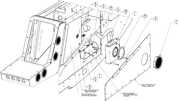
A/R |
13 |
MIL A 46106 |
ADHESIVE SEALANT, SILICONE RTV, ONE COMPONENT |
|
|
1 FT |
12 |
MIL R 6130 |
SILICONE SPONGE, MEDIUM DENSITY, GENERAL PURPOSE |
|
|
2 FT |
11 |
5700 1 |
AIRDUCT, FLEXIBLE, 5/8 INCH |
EDMO |
|
2 |
10 |
218089 |
CAP, EPDM, ID 0.625 [STOCKCAP.COM] |
|
|
5 |
9 |
MS3367 3 |
STRAP, TIEDOWN, ELECTRICAL COMPONENTS, ADJUSTABLE, SELF |
|
|
CLINCHING, PLASTIC |
|
||||
|
|
|
|
||
2 |
8 |
MB3APT |
MOUNTING BASE, CABLE TIE, HIGH TEMPERATURE, HEAVY BOND |
TYTON |
|
ADHESIVE |
|||||
|
|
|
|
||
7 |
7 |
MS20426AD3 3 |
RIVET, SOLID, COUNTERSUNK 100 DEG. PRECISION HEAD, 3 32 IN OD, |
|
|
3/16" LONG |
|
||||
|
|
|
|
||
2 |
6 |
MS21071L06 |
NUT, SLEF LOCKING, PLATE, ONE LUG, REDUCED RIVET SPACING, LOW |
|
|
HEIGHT, 0.1380 32UNJC 3B |
|
||||
|
|
|
|
||
2 |
5 |
AN525 832R6 |
SCREW, WASHER HEAD, CROSS RECESSED, 0.1640 32UNC 3A, 3/8 INCH |
|
|
LONG |
|
||||
|
|
|
|
||
2 |
4 |
MS51957 37 |
SCREW, MACHINE, PAN HEAD, CROSS RECESSED, CRES, 0.1380 32UNC 2A |
|
|
1 |
3 |
011 02558 00 |
LOUVER, ROUND, SCREENED, 3 INCH, BLACK, FAA PMA |
GARMIN |
|
1 |
2 |
190 01226 10 01 |
BRACKET, COOLING FAN |
|
|
1 |
1 |
013 00103 00 |
AVIONICS COOLING FAN WITH FAULT DETECTION |
GARMIN |
|
QTY. |
ITEM NO. |
PART NUMBER |
DESCRIPTION |
SUPPLIER |
500W Series |
190-01226-13 Rev. 3 |
Instructions for Continued Airworthiness Bell 407 |
Page 8 of 26 |
 Loading...