How it Works
Log In / Sign Up
Buy Points
How it Works
FAQ
Contact Us
Questions and Suggestions
Users
fanuc
Loading...
#
0-GCD
3
0-GSD
2
0i
2
0i A
8
0i-B
8
0i- C
5
0i- D
21
0i- F
0i-F Plus
8
0i-MA
0i Mate
3
0i Mate- B
0i Mate D
15
0i Mate-MB
4
0i Mate-TB
2
0i-MB
3
0i-MC
6
0i -MODEL C
0i-MODEL D
2
0i-MODEL F Plus
0i-PB
0i-PC
2
0i-PD
2
0i-TA
0i-TB
4
0i-TC
5
0i-TTC
2
0-Mate
0 Mate-MODEL D
2
0-MD
2
0-TD
3
150 B
7
150i
9
150 i A
6
150i- B
4
150i-MA
2
150i MB
2
15 B
9
15i
15 i A
7
15iB
4
15iMA
2
15i-MB
2
15-MB
5
15-TB
2
160B
5
160C
6
160i
160i-A
160i-B
2
160 i-LA
4
160i - MA
160i-MB
160is
160is-B
2
160is-MB
160PB
3
160TB
16B
5
16C
6
16i
2
16i-A
2
16i-B
2
16 i -LA
4
16i- MA
16i-MB
16PB
3
16TB
180- B
5
180-C
6
180i
180i-A
180i-B
2
180i-MB
180i-MB5
180is
180is-B
2
180is-MB
180is-MB5
180PB
3
180TB
18B
5
18C
6
10-100
11-110
12-120
Loading...
Loading...
Nothing found
15-MB
Connection Manual
378 pgs
4.37 Mb
14
Maintenance Manual
420 pgs
1.46 Mb
8
Operator’s Manual
487 pgs
3.7 Mb
5
Parameter Manual
422 pgs
2.33 Mb
6
Programming Manual
571 pgs
3.95 Mb
3
Table of contents
Loading...
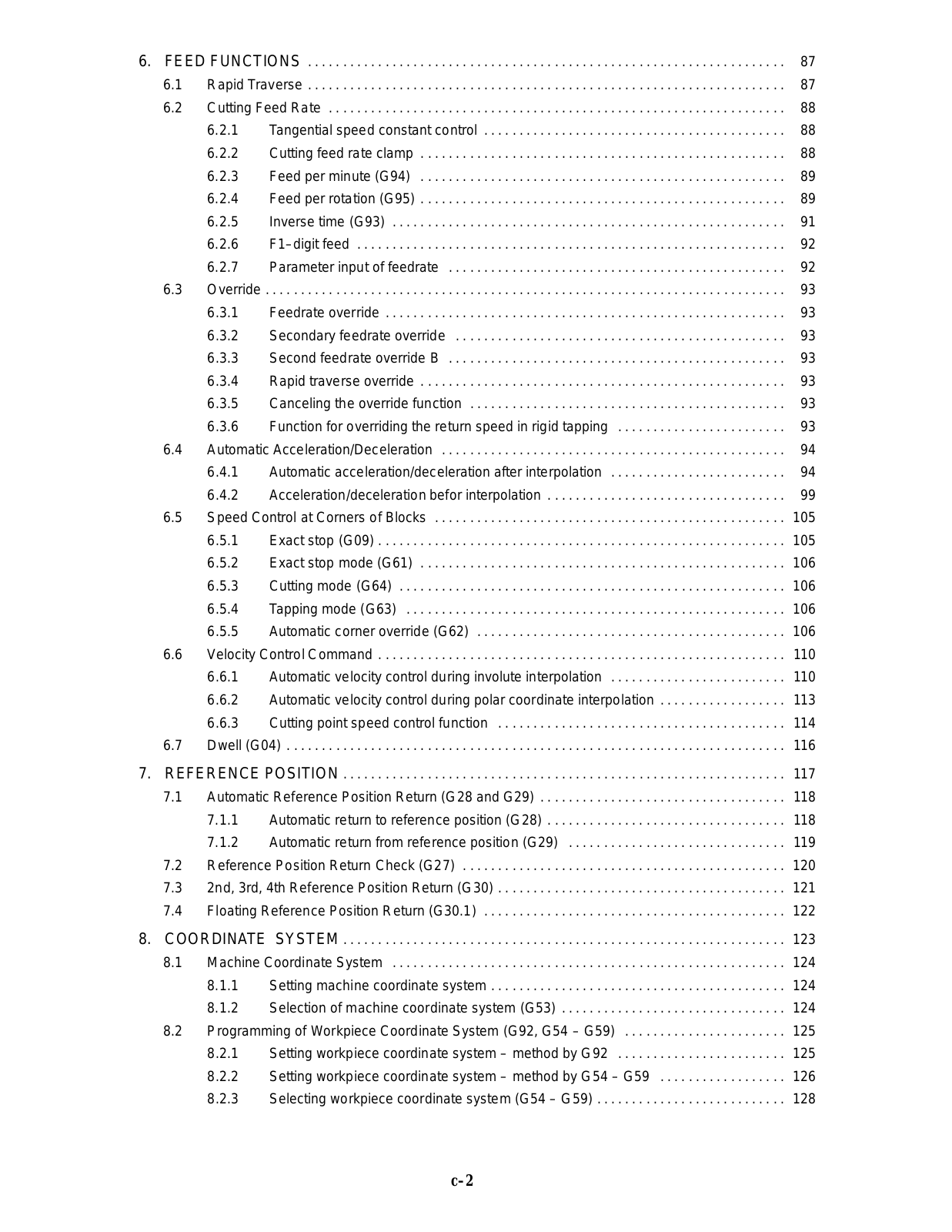
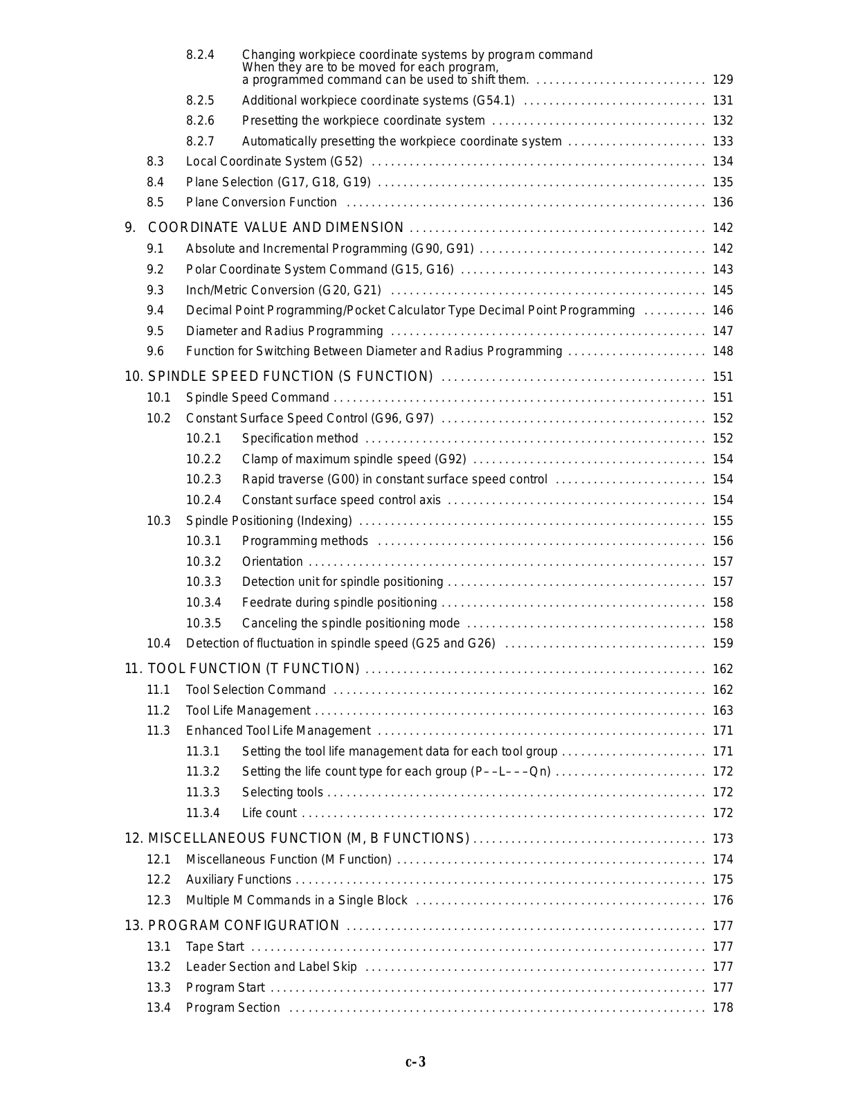
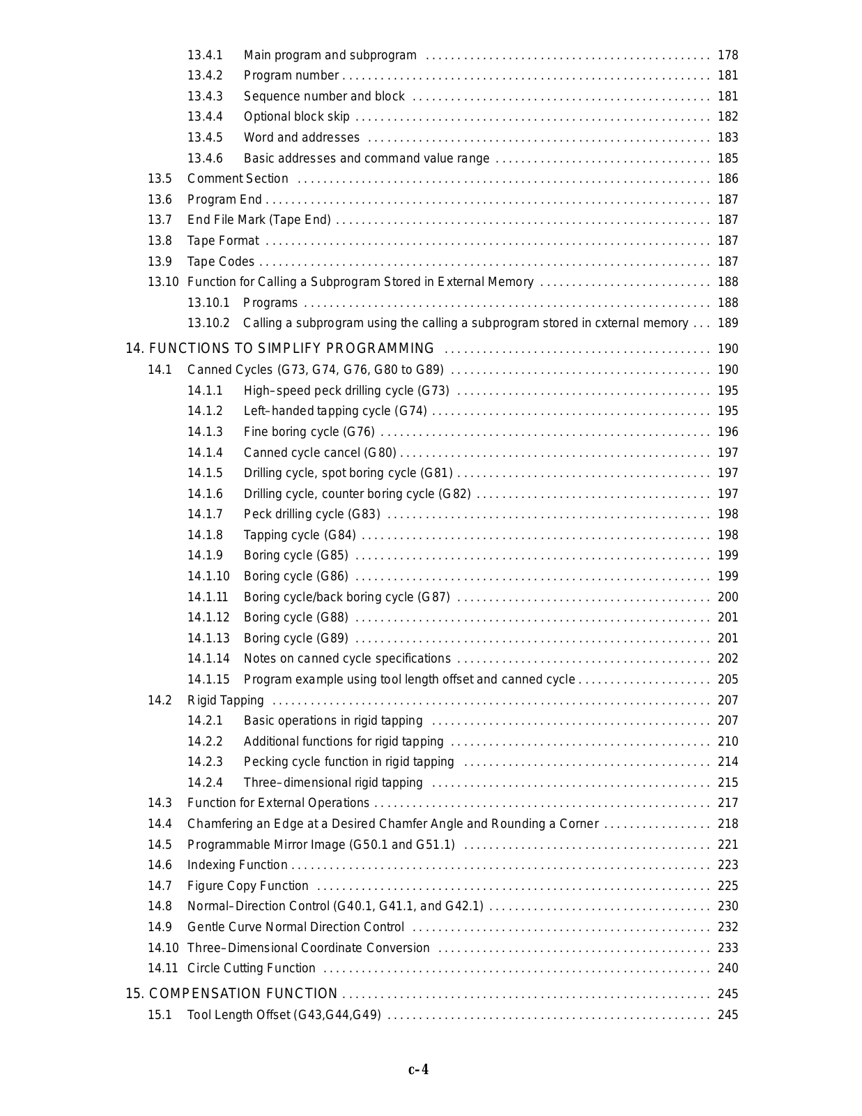
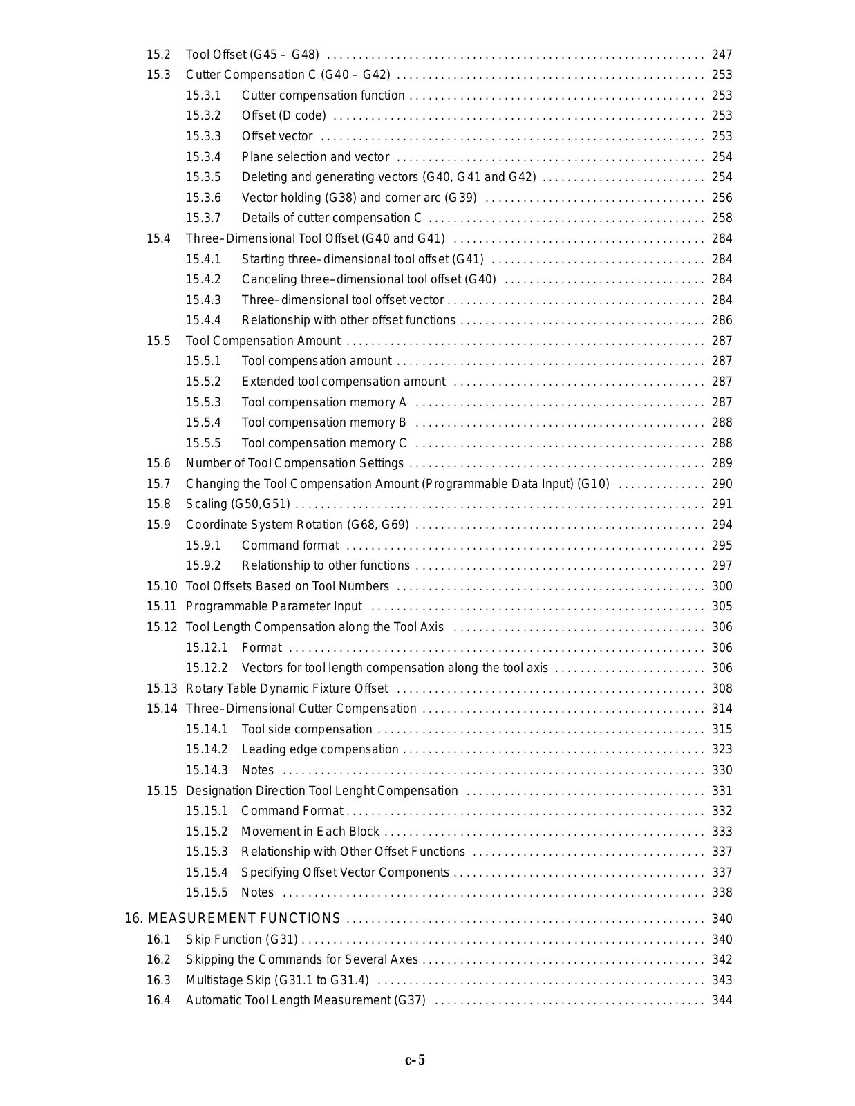
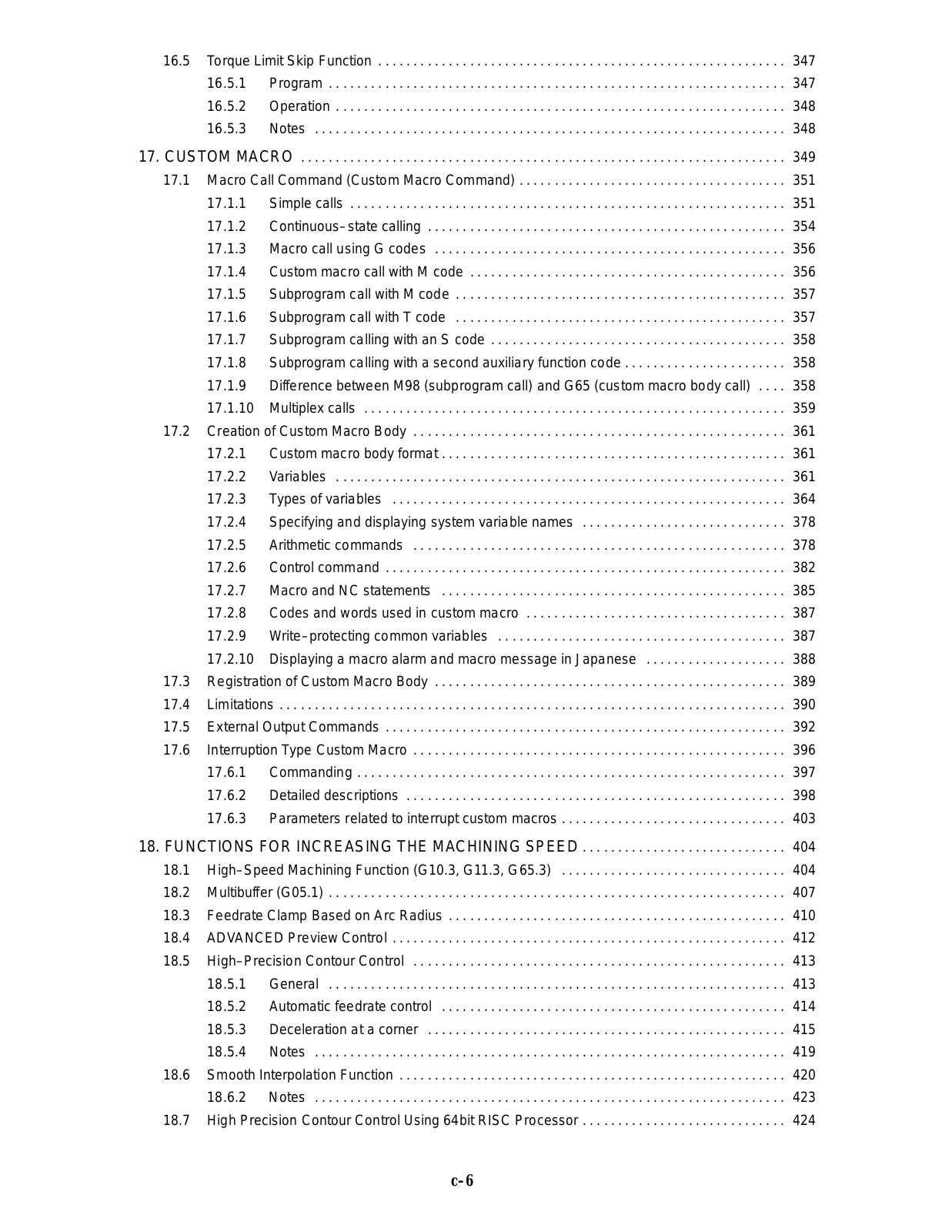
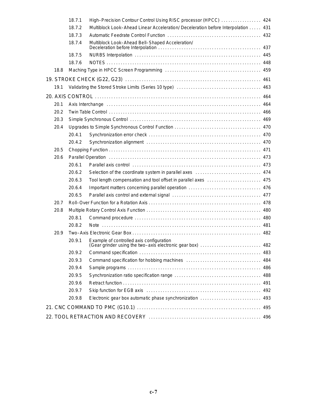
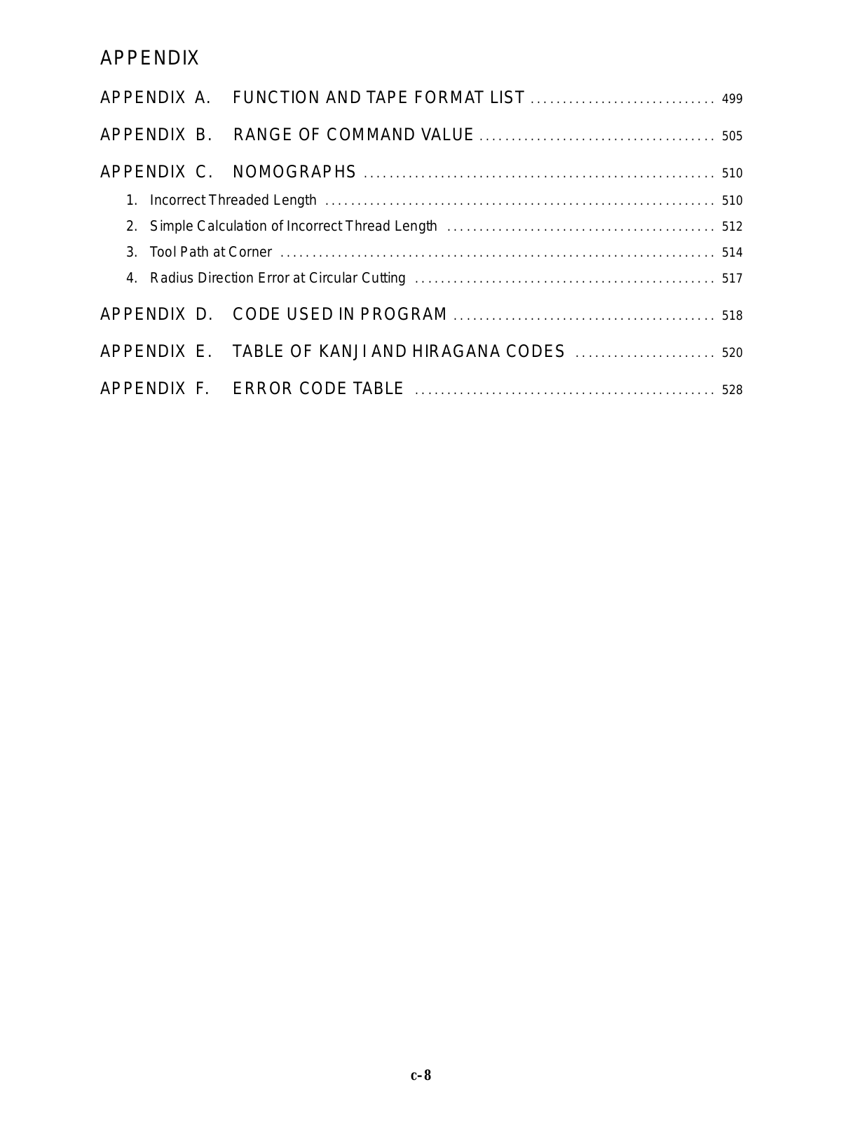
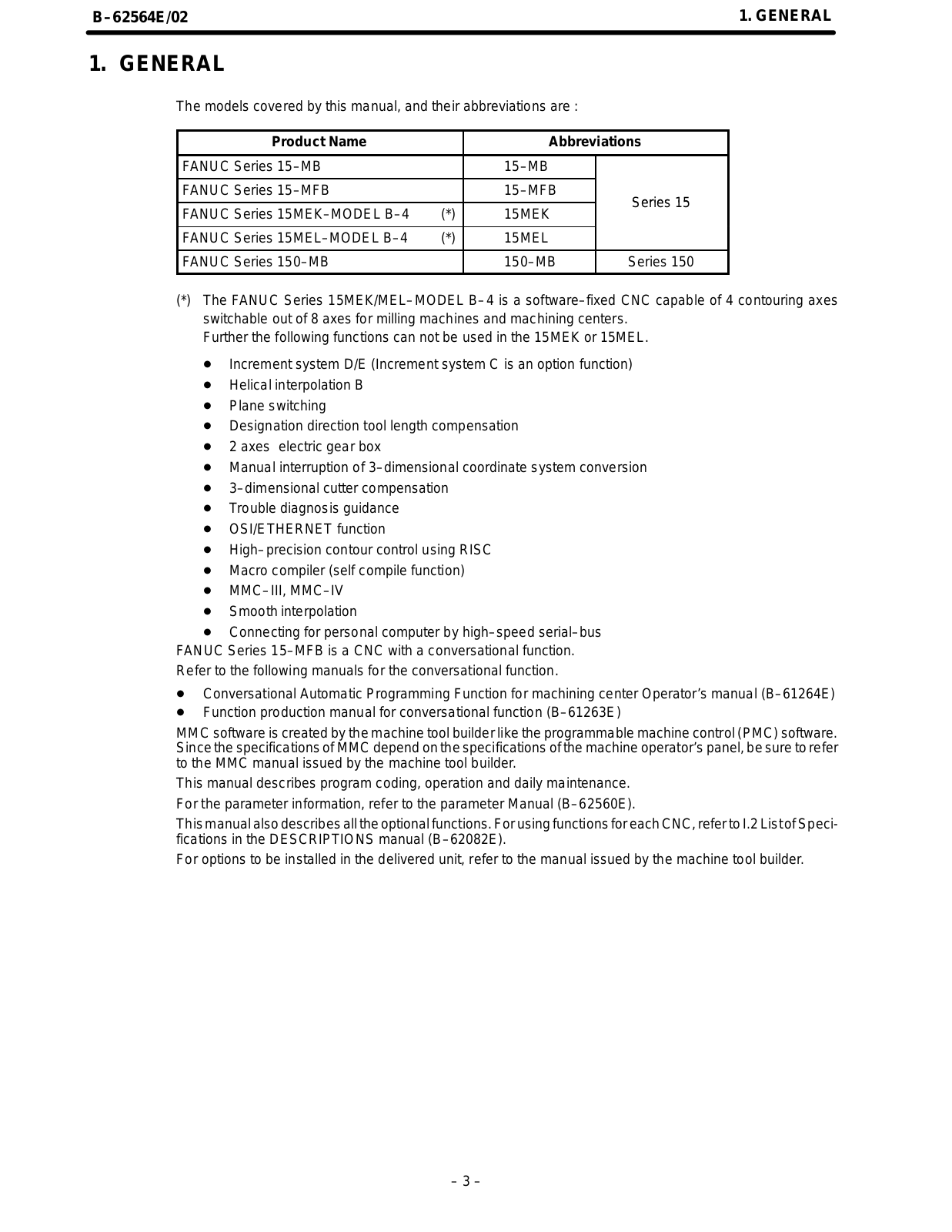
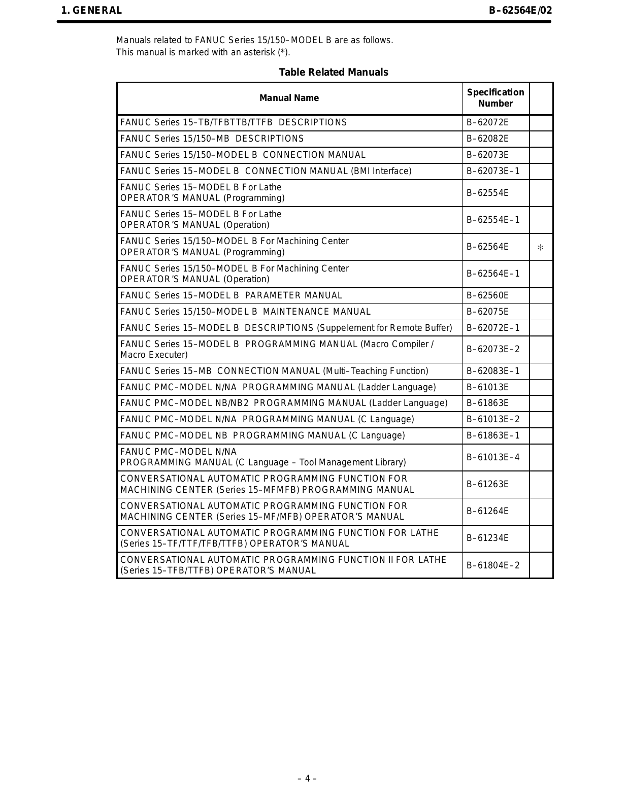
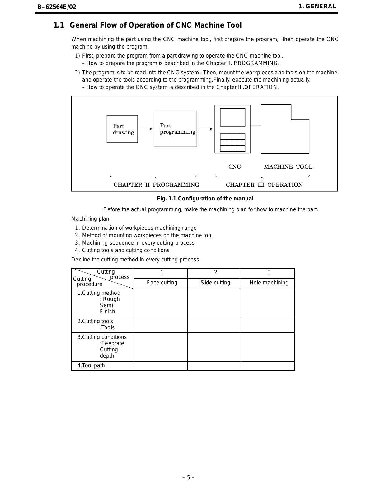
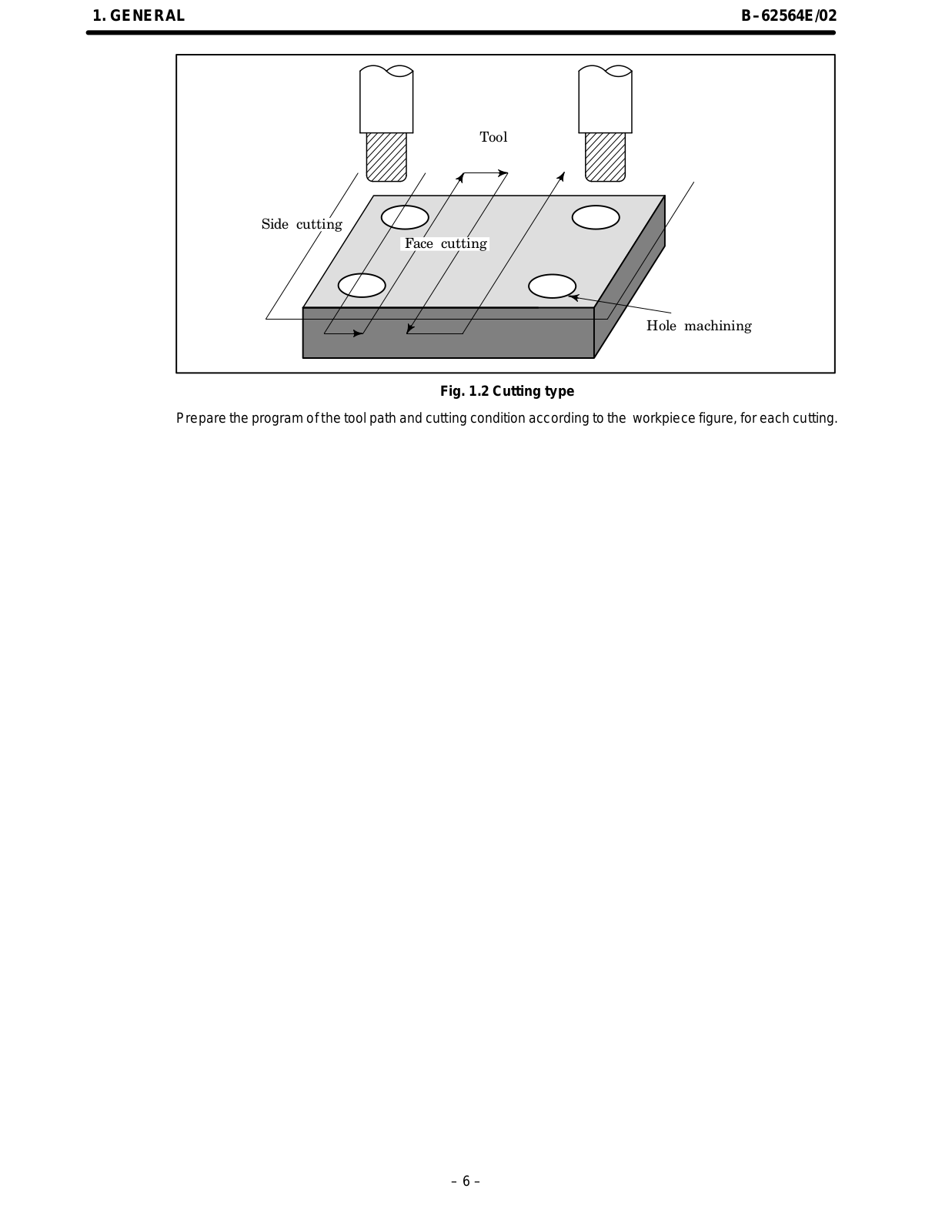
fanuc 15–MB Programming Manual
...
fanuc Programming Manual
Download
Specifications and Main Features
Frequently Asked Questions
User Manual
Download
Loading...
+
hidden pages
Unhide
You need points to download manuals.
1 point = 1 manual.
You can buy points or you can get point for every manual you upload.
Buy points
Upload your manuals
 Loading...