


GC-MT 1636/1
DOriginalbetriebsanleitung Benzin-Bodenhacke
GB Original operating instructions
Petrol hoe
FMode d’emploi d’origine Bineuse à essence
IIstruzioni per l’uso originali Zappa a benzina
DK/ Original betjeningsvejledning
N Benzindreven jordhakker
SOriginal-bruksanvisning Bensindriven jordfräs
HR/ |
Originalne upute za uporabu |
BIH |
Benzinska freza |
RS |
Originalna uputstva za upotrebu |
|
Benzinska freza |
CZ |
Originální návod k obsluze |
|
Benzínová motyčka |
SK |
Originálny návod na obsluhu |
|
Benzínový kyprič pôdy |
1

Art.-Nr.: 34.315.00 I.-Nr.: 11016
Anl_GC_MT_1636_1_SPK1.indb 1 |
31.08.2016 12:57:16 |
1 |
26 |
24 |
|
|
|
|
23 |
|
|
|
|
|
|
|
|
|
|
|
|
21
2a
22
20
15
4a
13a
2b
4b
13b
5
2 |
1 |
3a |
|
|
|
|
|
|
|
|
|
4b
3
- 2 -
Anl_GC_MT_1636_1_SPK1.indb 2 |
31.08.2016 12:57:16 |
3b |
|
|
|
4 |
|
|
|
|
|
|
|
16 |
|
|
|
|
|
|
|
|
|
|
|
|
|
|
|
|
|
|
|
|
|
|
|
|
|
|
|
|
4b |
|
15 |
|
|
|
|
|
|
|
|
|
|
|
|
|
|
|
|
|
|
|
|
5a |
|
22 |
|
|
|
|
|
|
|
|
|
5b |
27 |
|
|
|
|
|
|
|
|
|
|
|
|
|
|
|
|
||||||||
|
|
|
|
|
|
|
|
|
|
|
|
|
|
|
|
|
|
|
|
|
|
|
|
|
|
|
|
|
|
|
|||||||
|
|
|
|
|
|
|
|
|
|
|
|
|
|
|
|
|
|
|
|
|
|
|
29 |
|
|
|
|||||||||||
|
|
|
|
|
|
|
|
|
|
|
|
|
|
|
|
|
|
28 |
|
|
|
|
|
||||||||||||||
|
|
|
|
|
|
|
|
|
|
|
|
|
|
|
|
|
|
|
|
||||||||||||||||||
|
|
|
|
|
|
|
|
|
|
|
|
|
|
|
|
|
|
|
|
|
|
|
|||||||||||||||
|
|
|
|
|
|
|
|
|
|
|
|
|
|
|
|
|
|
|
|
|
|
|
|
|
|
|
|
|
|
|
|
|
|
|
|
|
|
|
|
|
|
|
|
|
|
|
|
|
|
|
|
|
|
|
|
|
|
30 |
|
|
|
||||||||||||||
|
21 |
|
|
|
|
|
|
|
|
|
|
|
|
|
|
31 |
|
|
|
|
|
||||||||||||||||
|
|
|
|
|
|
|
|
|
|
|
|
|
|
|
|
|
|
|
|
||||||||||||||||||
|
|
|
|
|
|
|
|
|
|
|
|
|
|
|
|
|
|
|
|
|
|
|
|
|
|
|
|
|
|
|
|
|
|
||||
|
|
|
|
|
|
|
|
|
|
|
|
|
|
24 |
|
32 |
|
|
|
|
|
|
|
|
|
|
|
|
|
|
|
|
|
|
|
||
|
|
|
|
|
|
|
|
|
|
|
|
|
|
|
|
|
|
|
|
|
|
|
|
|
|
|
|
|
|
|
|
|
|
||||
|
23 |
|
|
|
|
|
|
|
|
|
|
|
37 |
|
|
|
|
|
|
||||||||||||||||||
|
|
|
|
|
|
|
|
|
|
33 |
|
|
|
|
|
|
|
|
|||||||||||||||||||
|
|
|
|
|
|
|
|
|
|
|
|
||||||||||||||||||||||||||
|
|
|
|
|
|
|
|
|
|
|
|
|
|
|
|
|
|
|
|
|
|||||||||||||||||
|
|
|
|
|
|
|
|
|
|
|
|
|
|
|
|
|
|
|
|
|
|
|
|
|
|
|
|
|
|
|
|
|
|
|
|
|
|
|
|
|
|
|
|
|
|
|
|
|
|
|
|
|
|
|
|
|
|
|
|
|
|
|
|
|
|
|
|
|
|
|
|
|
|
|
|
|
|
|
|
|
|
|
|
|
|
|
|
|
|
|
|
|
|
|
|
|
|
|
|
|
|
|
|
|
|
|
|
|
|
|
|
|
|
|
|
|
|
|
|
|
|
|
|
|
|
|
|
|
|
|
|
|
|
|
|
|
|
|
|
|
|
|
|
|
|||||||
5c |
|
|
|
|
|
|
|
22 |
|
5d |
|
|
|
|
|
|
|
|
|
|
|
|
|
|
|
|
|
||||||||||
|
|
|
|
|
|
|
|
|
|
|
|
|
|
|
|
|
|
|
|
|
|
|
|
||||||||||||||
|
|
|
|
|
|
|
|
|
|
|
|
|
|
|
|
|
|
|
|
|
|
|
|
|
|
|
|
|
|
|
|
|
|
|
|||
|
21 |
|
|
|
|
|
|
|
|
|
|
|
|
|
|
|
|
|
|
|
|
|
|
|
|
|
|
|
|
|
|
|
|||||
|
|
|
|
|
33 |
|
|
|
|
|
|
|
23 |
|
|
|
|
|
|
|
|
||||||||||||||||
|
|
|
|
|
|
|
|
|
|
|
|
|
|
|
|
|
|
|
|
|
|
||||||||||||||||
|
|
|
|
|
|
|
|
|
|
|
|
|
|
|
|
|
|
||||||||||||||||||||
|
32 |
31 |
|
|
|
|
|
|
|
|
|
|
|
|
|
|
|
|
|
|
|
|
|
|
|
|
|
|
|
|
|
|
|||||
|
|
|
|
|
|
|
|
|
|
|
|
|
|
|
|
|
|
|
|
|
|
|
|
|
|
|
|
|
|
|
|||||||
|
|
|
|
|
|
|
|
|
|
|
|
|
|
|
|
|
|
|
|
|
|
|
|
|
|
|
|
|
|
|
|
||||||
|
|
|
|
|
|
|
|
|
|
|
|
|
|
|
|
|
|
22 |
28 |
|
|
|
|
|
|
|
|
|
|
|
|||||||
|
|
|
|
|
|
|
|
|
|
|
|
|
|
|
|
|
|
|
|
|
|
|
|
|
|
|
|
|
|
|
|
||||||
|
|
|
|
|
|
|
|
|
|
|
|
|
|
|
|
|
|
|
|
|
|
|
|
|
|
|
|
|
|
|
|||||||
|
|
|
|
|
|
|
|
|
|
|
|
|
|
|
|
|
|
|
|
|
|
|
|
|
21 27 |
|
|
|
|
||||||||
|
|
|
|
|
|
|
|
|
|
|
|
|
|
|
|
|
|
|
|
|
|
|
|
|
|
||||||||||||
|
|
|
|
|
|
|
|
|
|
|
|
|
|
|
|
|
|
|
|
|
|
|
|
|
|
|
|
|
|
|
|
|
|
|
|
|
|
|
|
|
|
|
|
|
|
|
|
|
|
|
|
|
|
|
- 3 - |
|
|
|
|
|
|
|
|
|
|
|
|
|
|
|
|
|
|
|
|
Anl_GC_MT_1636_1_SPK1.indb 3 |
31.08.2016 12:57:17 |
5e |
|
|
21 |
|
|
|
A |
B |
5g |
|
|
|
22 |
|
|
|
26 |
6a |
|
|
|
|
5 |
|
|
- 4 - |
Anl_GC_MT_1636_1_SPK1.indb |
4 |
|
5f |
24 |
C |
30 |
29 |
5h |
37 |
6b |
5 |
31.08.2016 12:57:20

6c |
|
7 |
|
22 |
26 |
8b
Anl_GC_MT_1636_1_SPK1.indb 5
6d |
|
|
24 |
1. |
2. |
|
|
25 |
|
8a |
|
9 |
|
D |
|
- 5 - |
|
31.08.2016 |
12:57:25 |
10a |
F |
10b |
|
E |
|
|
|
|
|
H |
L |
11 |
|
|
|
1 |
2 |
3 |
|
|
|
|
|
|
|
|
|
|
|
|
|
|
|
|
|
|
|
|
|
|
|
|
|
|
|
|
|
|
|
|
|
|
|
|
|
|
|
|
|
|
|
|
|
|
|
|
|
|
|
|
|
|
|
|
|
|
|
|
|
|
|
|
|
|
|
|
|
|
|
|
|
|
|
|
|
|
|
|
|
|
|
|
|
|
|
|
|
|
|
|
|
|
|
|
|
|
|
|
|
|
|
|
|
|
|
|
|
|
|
|
|
|
|
|
|
|
|
|
|
|
|
|
|
|
|
|
|
|
|
|
|
|
|
|
4 |
|
|
5 |
|
6 |
|
|
|
|
|
|
|||||||||||||||
- 6 -
Anl_GC_MT_1636_1_SPK1.indb 6 |
31.08.2016 12:57:29 |

D
Gefahr!
Beim Benutzen von Geräten müssen einige Sicherheitsvorkehrungen eingehalten werden, um Verletzungen und Schäden zu verhindern. Lesen Sie diese Bedienungsanleitung / Sicherheitshinweise deshalb sorgfältig durch. Bewahren Sie diese gut auf, damit Ihnen die Informationen jederzeit zur Verfügung stehen. Falls Sie das Gerät an andere Personen übergeben sollten, händigen Sie diese Bedienungsanleitung / Sicherheitshinweise bitte mit aus. Wir übernehmen keine Haftung für Unfälle oder Schäden, die durch Nichtbeachten dieser Anleitung und den Sicherheitshinweisen entstehen.
1. Sicherheitshinweise
Die entsprechenden Sicherheitshinweise finden Sie im beiliegenden Heftchen!
Gefahr!
Lesen Sie alle Sicherheitshinweise und Anweisungen. Versäumnisse bei der Einhaltung der Sicherheitshinweise und Anweisungen können elektrischen Schlag, Brand und/oder schwere Verletzungen verursachen. Bewahren Sie alle
Sicherheitshinweise und Anweisungen für die Zukunft auf.
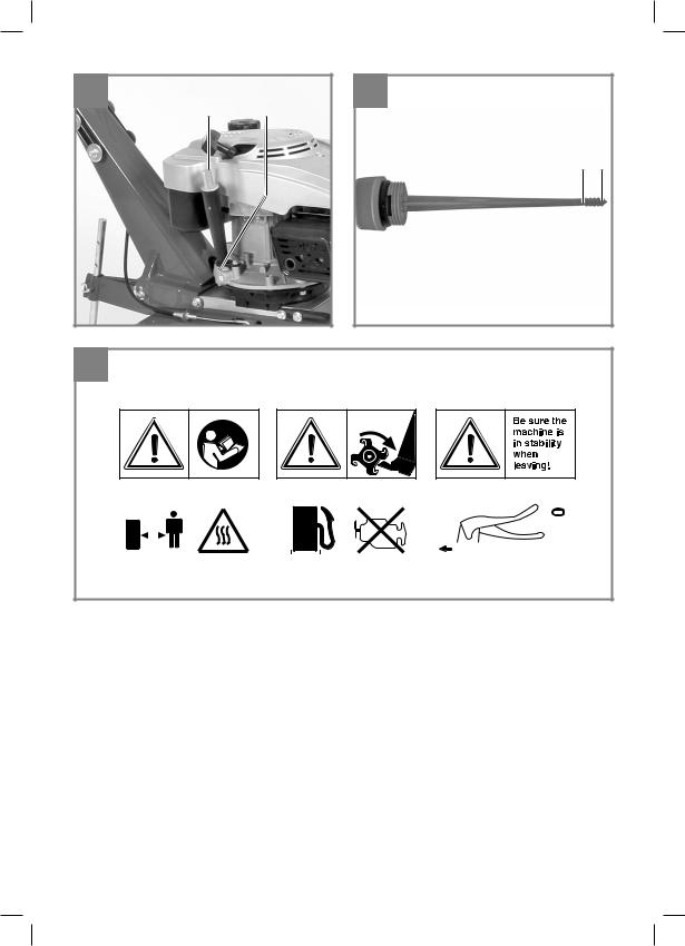
Erklärung des Hinweisschildes auf dem Gerät (siehe Bild 11)
1Achtung! Bedienungsanleitung lesen. Warnund Sicherheitshinweise befolgen.
2Achtung! Verletzungsgefahr durch rotierende Teile. Halten Sie Hände, Füße und Kleidung fern.
3Achten Sie auf sicheren Stand der Maschine wenn Sie diese verlassen.
4Achtung! Heisse Teile. Abstand halten.
5Achtung! Während des Tankens Motor abstellen.
6Beschreibung Kupplungshebel: 0 = Hackmesser Stop; 1 = Hackmesser Ein
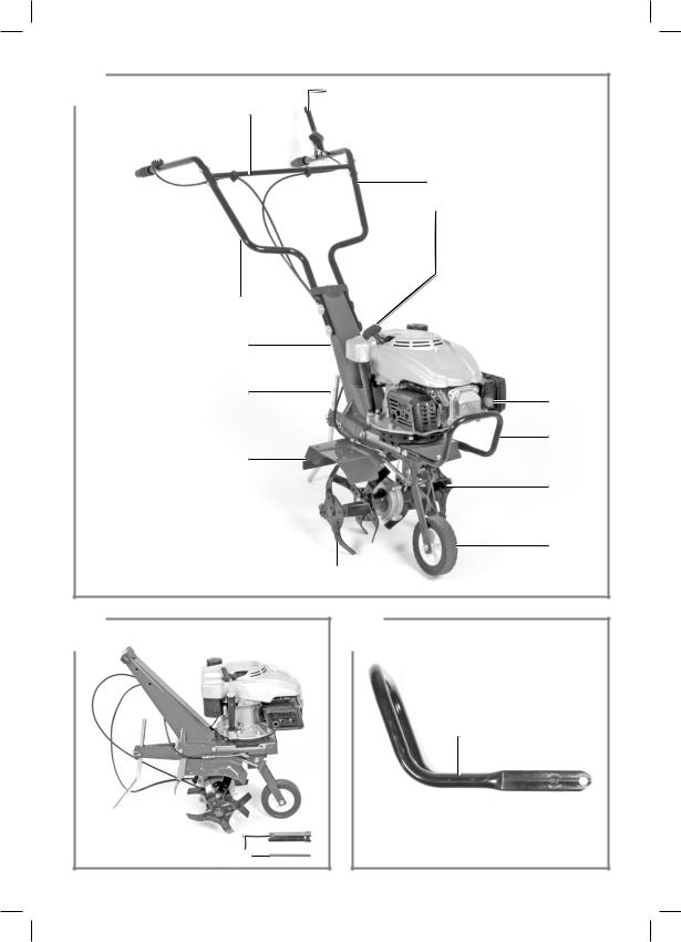
2. Gerätebeschreibung und Lieferumfang
2.1 Gerätebeschreibung
1. Motor-/ Getriebeeinheit
2a. Reversierstarter
2b. Kraftsto pumpe (Primer)
3. Zündkerzenschlüssel
Montageset für Schutzblech/Transportrad/ Bügel (Abb. 3a/3b):
4a. Schutzblech (*)
4b. Bügel
4c. 4x Schraube M8 x 25 (*)
5.Transportrad (*)
6.4x Schraube M8x20 (*)
7.4x Federring Ø8 (*)
8.4x Unterlegscheibe Ø8 (*)
9.1x Schraube M10x65 (*)
10.1x Mutter M10 (*)
11.1x Feder (*)
12.1x Sicherungssplint klein (*)
(*) nicht abgebildet, bereits vormontiert
Montageset für Hackmesser/Tiefenanschlag (Abb. 4a):
13a.Hackmesser rechts (*) 13b. Hackmesser links (*)
14.2x Schutzkappe (*)
15.Tiefenanschlag (*)
16.Sicherungssplint groß (*)
17.4x Schraube M8x35 (*)
18.4x Unterlegscheibe Ø8 (*)
19.4x Mutter M8 (*)
(*) nicht abgebildet, bereits vormontiert
Montageset für Fahrbügel / Kupplungshebel / Start / Stopp-Hebel (Abb. 5a/5b):
20.Fahrbügelhalter (*)
21.Fahrbügel – Kupplungshebel
22.Fahrbügel – Start/Stopp – Hebel
23.Querstrebe
24.Kupplungshebel
25.Sicherungshebel
26.Start/Stopp – Hebel
27.4x Schraube M8x35
28.4x Mutter M8
29.1x Schraube M8x40
30.1x Hutmutter M8
31.4x Schraube M8x30
32.4x Unterlegscheibe groß Ø8
33.4x Mutter M8
34.4x Schraube M8x20 (*)
35.4x Federring Ø8 (*)
36.4x Unterlegscheibe Ø8 (*)
37.2x Kabelclip
(*) nicht abgebildet, bereits vormontiert
- 7 -
Anl_GC_MT_1636_1_SPK1.indb 7 |
31.08.2016 12:57:30 |

D
2.2 Lieferumfang
Bitte überprüfen Sie die Vollständigkeit des Artikels anhand des beschriebenen Lieferumfangs. Bei Fehlteilen wenden Sie sich bitte spätestens innerhalb von 5 Arbeitstagen nach Kauf des Artikels unter Vorlage eines gültigen Kaufbeleges an unser Service Center oder an die Verkaufstelle, bei der Sie das Gerät erworben haben. Bitte beachten Sie hierzu die Gewährleistungstabelle in den Service-Informationen am Ende der Anleitung.
•Öffnen Sie die Verpackung und nehmen Sie das Gerät vorsichtig aus der Verpackung.
•Entfernen Sie das Verpackungsmaterial sowie Verpackungs-/ und Transportsicherungen (falls vorhanden).
•Überprüfen Sie, ob der Lieferumfang vollständig ist.
•Kontrollieren Sie das Gerät und die Zubehörteile auf Transportschäden.
•Bewahren Sie die Verpackung nach Möglichkeit bis zum Ablauf der Garantiezeit auf.
Gefahr!
Gerät und Verpackungsmaterial sind kein Kinderspielzeug! Kinder dürfen nicht mit Kunststo beuteln, Folien und Kleinteilen spielen! Es besteht Verschluckungsund Erstickungsgefahr!
•Originalbetriebsanleitung
•Sicherheitshinweise
3.Bestimmungsgemäße Verwendung
Das Gerät ist geeignet zum Umgraben von Beeten und Ackern. Beachten Sie unbedingt die Einschränkungen in den zusätzlichen Sicherheitshinweisen.
Die Maschine darf nur nach ihrer Bestimmung verwendet werden. Jede weitere darüber hinausgehende Verwendung ist nicht bestimmungsgemäß. Für daraus hervorgerufene Schäden oder Verletzungen aller Art haftet der Benutzer/Bediener und nicht der Hersteller.
Bitte beachten Sie, dass unsere Geräte bestimmungsgemäß nicht für den gewerblichen, handwerklichen oder industriellen Einsatz konstruiert wurden. Wir übernehmen keine Gewährleistung, wenn das Gerät in Gewerbe-, Handwerksoder
Industriebetrieben sowie bei gleichzusetzenden Tätigkeiten eingesetzt wird.
4. Technische Daten
Motor: ........................................... |
4-Takt, 99 cm3 |
Motorleistung: .............................. |
1,5 kW / (2) PS |
Arbeitsdrehzahl Motor: ........................ |
3200 min-1 |
Arbeitsbreite: .............................................. |
36 cm |
Hackmesser Ø: .......................................... |
26 cm |
Vorwärtsgang: ................................................... |
1 |
Startsystem: ................. |
Reversierstarteinrichtung |
Kraftsto : .................................................. |
Benzin |
Motoröl: .................................................... |
ca.0,4 l |
Tankinhalt: ............................................... |
ca. 1,5 l |
Vibration ahv: ............................................... |
7 m/s2 |
Unsicherheit K:......................................... |
1,5 m/s2 |
Gewicht: ...................................................... |
30 kg |
Zündkerze: ............................................... |
F7RTC |
Schalldruckpegel LpA........................... |
79,2 dB(A) |
Unsicherheit KpA............................................ |
3 dB |
Garantierter Schallleistungspegel LWA .... 93 dB(A)
5. Vor Inbetriebnahme
Montage Schutzblech, Bügel und Transportrad
1.Legen Sie sich die Bauteile wie unter Punkt 2.1 Lieferumfang beschrieben zurecht.
2.Bügel (4b) wie in Abb. 3b gezeigt montieren.
Montage Hackmesser und Tiefenanschlag
Zu Arbeitsbeginn empfehlen wir den Tiefenanschlag in mittlerer der 3 möglichen Positionen zu fixieren. Soll die Arbeitstiefe verändert werden, verschieben Sie die Position des Tiefenanschlags nach oben oder unten.
- 8 -
Anl_GC_MT_1636_1_SPK1.indb 8 |
31.08.2016 12:57:30 |

D
Montage Fahrbügel, Kupplungshebel und Start/Stopp – Hebel
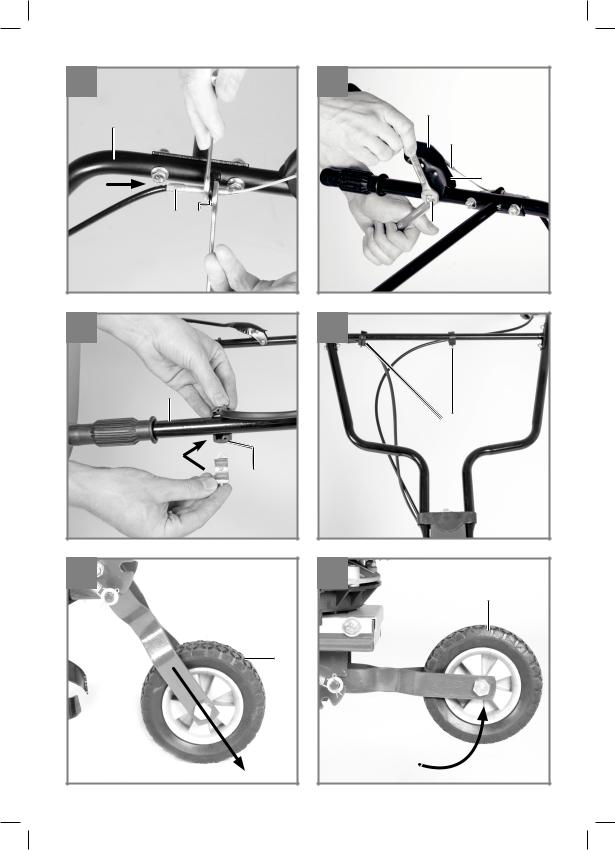
1.Legen Sie sich die Bauteile wie unter Punkt 2.1 Lieferumfang beschrieben zurecht.
2.Fahrbügel – Kupplungshebel (21) und Fahrbügel – Start/Stopp – Hebel (Pos. 22) wie in Abb. 5c gezeigt montieren.
3.Querstrebe (23) wie in Abb. 5d gezeigt montieren.
4.Kupplungshebel (24) montieren ist einfach, wenn Sie folgende Schritte einhalten:
- Schieben Sie die Bowdenzughülle (Abb. 5e/ Pos. A) in die in Öse (Abb. 5e/Pos. B). Stellen Sie den Bowdenzug durch Verdrehen der Kontermuttern auf maximale Länge ein.
- Hängen Sie den Bowdenzug (Abb. 5f/ Pos. C) am Kupplungshebel (24) ein und montieren Sie den Kupplungshebel am Fahrbügel. Achten Sie dabei auf korrekten Sitz des Sicherungshebels. Führen Sie eine Funktionsprüfung durch. Ziehen Sie den Sicherungshebel (25) wie in Abb. 6d gezeigt
zum Kupplungshebel. Der Kupplungshebel ist entsperrt und kann betätigt werden.
5.Stellen Sie die Seilzuglänge wie in Absatz 7.2.4 beschrieben ein.
6.Start/Stopp – Hebel (26) wie in Abb. 5g gezeigt montieren.
7.Kabelclip (37) wie in Abb. 5h gezeigt montieren.
Achtung! Bei Erstbetriebnahme muss Motorenöl und Kraftsto eingefüllt werden.
•Kraftstoffund Motorenölstand prüfen, eventuell nachfüllen.
•Vergewissern Sie sich, dass das Zündkabel an der Zündkerze befestigt ist
•Die unmittelbare Umgebung der Motorhacke begutachten
6. Bedienung
•Tiefenanschlag (Abb. 4 / Pos. 15) auf richtige Höhe einstellen und mit Splint sichern.
•Transportrad nach oben schwenken und darauf achten, dass der Bolzen der Rasterung in der Aufnahme nach vorne eingerastet ist (Abb.6a-6b).
•Je nach Körpergröße können Sie die Fahrbügel einstellen. Dazu die Schrauben (Abb.6c) lösen, Konsole einstellen und Schrauben wieder festziehen.
•Um die Hacksterne in Betrieb zu setzen, den Sicherungshebel (25) nach oben ziehen, den Kupplungshebel (24) nach unten drücken und halten (Abb. 6d). Nach Loslassen des Kupplungshebels bleiben die Hacksterne stehen (falls diese nicht stehen bleiben sollten, Kupplungsseil nachstellen).
Motor Starten
1.Vergewissern Sie sich, dass das Zündkabel an der Zündkerze angeschlossen ist.
2.Stehen Sie hinter der Bodenhacke. Stellen Sie den Motor Start/Stopp-Hebel (Abb.7/Pos. 26) in Position ON.
3.Kraftsto pumpe (Primer) Abb. 1/Pos. 2b) 3x drücken. Bei warmgelaufenem Motor kann dieser Punkt entfallen.
4.Den Motor mit dem Reversierstarter (Abb.1/ Pos. 2a) starten. Hierfür den Gri ca. 10-15 cm (bis ein Widerstand spürbar ist) herausziehen, dann kräftig mit einem Ruck anziehen. Sollte der Motor nicht gestartet haben, nochmals am Gri anziehen.
Hinweis! Den Seilzug nicht zurückschleudern lassen.
Hinweis! Bei kühlem Wetter kann es erforderlich sein, den Anlassvorgang mehrmals zu wiederholen.
Motor Stoppen
Stellen Sie den Motor Start/Stopp - Hebel (26) in Position STOP.
- 9 -
Anl_GC_MT_1636_1_SPK1.indb 9 |
31.08.2016 12:57:30 |

D
7.Reinigung, Wartung, Lagerung und Ersatzteilbestellung
Gefahr!
Ziehen Sie vor allen Reinigungsund Wartungsarbeiten den Zündkerzenstecker.
7.1 Reinigung
•Halten Sie Schutzvorrichtungen, Luftschlitze und Motorengehäuse so staubund schmutzfrei wie möglich. Reiben Sie das Gerät mit einem sauberen Tuch ab oder blasen Sie es mit Druckluft bei niedrigem Druck aus.
•Wir empfehlen, dass Sie das Gerät direkt nach jeder Benutzung reinigen.
•Reinigen Sie das Gerät regelmäßig mit einem feuchten Tuch und etwas Schmierseife. Verwenden Sie keine Reinigungsoder Lösungsmittel; diese könnten die Kunststoffteile des Gerätes angreifen. Achten Sie darauf, dass kein Wasser in das Geräteinnere gelangen kann.
7.2 Wartung
Achtung: Stellen Sie das Gerät sofort ab und wenden Sie sich an ihren autorisierten Fachhändler:
•Bei ungewöhnlichen Schwingungen oder Geräuschen.
•Wenn der Motor überlastet scheint, oder Fehlzündungen hat.
7.2.1 Luftfilter warten
•Luftfilter vor jedem Gebrauch prüfen, reinigen, wenn nötig tauschen.
•Entnehmen Sie das Filterelement (Abb. 8a8b).
•Zum Reinigen des Elementes dürfen keine scharfen Reiniger oder Benzin verwendet werden.
•Das Element durch Ausklopfen auf einer flachen Fläche reinigen.
•Der Zusammenbau erfolgt in umgekehrter Reihenfolge.
7.2.2 Zündkerze warten
Überprüfen Sie die Zündkerze erstmals nach 10 Betriebsstunden auf Verschmutzung und reinigen Sie diese gegebenenfalls mit einer Kupferdrahtbürste. Danach die Zündkerze alle 50 Betriebsstunden warten.
•Ziehen Sie den Zündkerzenstecker (Abb. 9) mit einer Drehbewegung ab.
•Entfernen Sie die Zündkerze (Abb. 9/Pos.D)
mit dem beiliegendem Zündkerzenschlüssel.
•Der Zusammenbau erfolgt in umgekehrter Reihenfolge.
7.2.3 Ölwechsel/ Ölstand prüfen (vor jedem Gebrauch)
Der Motorölwechsel sollte bei betriebswarmem Motor durchgeführt werden.
•Ölmessstab (Abb. 10a / Pos.E) herausnehmen.
•Ölablassschraube (Abb. 10a / Pos.F) öffnen und warmes Motoröl in einen Auffangbehälter ablassen.
•Nach Auslaufen des Altöls Ölablassschraube schließen.
•Motoröl bis zur oberen Markierung des Ölmessstabes (Abb. 10b/H) einfüllen.
•Achtung Ölmessstab zum Ölstandprüfen nicht einschrauben, sondern nur bis zum Gewinde einstecken (H = Max. / L= Min.).
•Das Altöl muss ordentlich entsorgt werden.
7.2.4 Einstellen der Bowdenzüge
In der Arbeitsstellung soll der Kupplungshebel mit geringem Kraftaufwand bis zum Schubbügel hinabgedrückt werden können. Wenn der Bowdenzug dabei zu stra gespannt ist, muss dieser länger eingestellt werden. Dazu lösen Sie die Kontermutter gegenüber dem Hauptseilzug, verlängern die Schraubenverbindung und ziehen anschließend die Kontermutter wieder fest (siehe Abb.5e). Falls die Hacksterne nicht mehr rotieren, muss die Schraubenverbindung (analog wie vorher beschrieben) verkürzt werden.
7.2.5 Getriebe der Motorhacke
Der Antrieb des Getriebes erfolgt über einen Keilriemen. Das Getriebe kann gegebenenfalls repariert werden. Wenden Sie sich hierfür an den Kundendienst.
7.3 Lagerung
Entleeren Sie den Kraftsto tank bevor Sie das Gerät für längere Zeit außer Betrieb nehmen. Reinigen Sie das Gerät und benetzten Sie alle Metallteile mit einem dünnen Ölfilm, zum Schutz vor Verrostung. Lagern Sie das Gerät in einem sauberen und trockenen Raum.
- 10 -
Anl_GC_MT_1636_1_SPK1.indb 10 |
31.08.2016 12:57:30 |
D
7.4 Ersatzteilbestellung:
Bei der Ersatzteilbestellung sollten folgende Angaben gemacht werden;
•Typ des Gerätes
•Artikelnummer des Gerätes
•Ident-Nummer des Gerätes
•Ersatzteilnummer des erforderlichen Ersatzteils
Aktuelle Preise und Infos finden Sie unter www.isc-gmbh.info
8.Entsorgung und Wiederverwertung
Das Gerät befindet sich in einer Verpackung um Transportschäden zu verhindern. Diese Verpackung ist Rohsto und ist somit wieder verwendbar oder kann dem Rohsto kreislauf zurückgeführt werden. Das Gerät und dessen Zubehör bestehen aus verschiedenen Materialien, wie z.B. Metall und Kunststo e. Defekte Geräte gehören nicht in den Hausmüll. Zur fachgerechten Entsorgung sollte das Gerät an einer geeigneten Sammelstellen abgegeben werden. Wenn Ihnen keine Sammelstelle bekannt ist, sollten Sie bei der Gemeindeverwaltung nachfragen.
- 11 -
Anl_GC_MT_1636_1_SPK1.indb 11 |
31.08.2016 12:57:30 |

D
9. Fehlersuchplan
Warnhinweis: Zuerst den Motor abschalten und den Zündkerzenstecker abziehen, bevor Inspektionen oder Justierungen vorgenommen werden.
Warnhinweis: Wenn nach einer Justierung oder Reparatur der Motor einige Minuten gelaufen ist, denken Sie daran, dass der Auspu und andere Teile heiß sind. Also nicht berühren, um Verbrennungen zu vermeiden.
Störung |
|
Mögliche Ursache |
|
Behebung |
Unruhiger Lauf, |
- |
Schrauben lose |
- |
Schrauben prüfen |
starkes Vibrieren |
- |
Zündkerze defekt |
- |
Zündkerze erneuern |
des Gerätes |
|
|
|
|
Motor läuft nicht |
- |
Zündkerze defekt |
- |
Zündkerze erneuern |
|
- |
Kraftsto tank leer |
- |
Kraftsto einfüllen |
Motor läuft unruhig |
- |
Luftfilter verschmutzt |
- |
Luftfilter reinigen |
|
- |
Zündkerze verschmutzt, defekt |
- |
Zündkerze reinigen, erneuern |
Antriebskraft lässt |
- |
Kupplungsspiel zu groß |
- |
Kupplungsseil einstellen |
nach |
- |
Keilriemen lose |
- |
Autorisierten Kundendienst aufsu- |
|
|
|
|
chen |
Motor kann nicht |
- |
Zündkerze verrußt |
- |
Zündkerze reinigen |
gestartet werden |
- |
kein Kraftsto |
- |
Kraftsto nachfüllen |
oder stirbt nach kur- |
|
|
|
|
zer Zeit ab |
|
|
|
|
Der Nachdruck oder sonstige Vervielfältigung von Dokumentation und Begleitpapieren der Produkte, auch auszugsweise, ist nur mit ausdrücklicher Zustimmung der iSC GmbH zulässig.
Technische Änderungen vorbehalten
- 12 -
Anl_GC_MT_1636_1_SPK1.indb 12 |
31.08.2016 12:57:30 |

D
Service-Informationen
Wir unterhalten in allen Ländern, welche in der Garantieurkunde benannt sind, kompetente ServicePartner, deren Kontakte Sie der Garantieurkunde entnehmen. Diese stehen Ihnen für alle ServiceBelange wie Reparatur, Ersatzteilund Verschleißteil-Versorgung oder den Bezug von Verbrauchsmaterialien zur Verfügung.
Es ist zu beachten, dass bei diesem Produkt folgende Teile einem gebrauchsgemäßen oder natürlichen Verschleiß unterliegen bzw. folgende Teile als Verbrauchsmaterialien benötigt werden.
Kategorie |
Beispiel |
Verschleißteile* |
Zündkerze, Luftfilter, Hackmesser, Keilriemen, |
|
Kupplung, Kraftsto filter |
Verbrauchsmaterial/ Verbrauchsteile* |
|
Fehlteile |
|
* nicht zwingend im Lieferumfang enthalten! |
|
Bei Mängel oder Fehlern bitten wir Sie, den Fehlerfall im Internet unter www.isc-gmbh.info anzumelden. Bitte achten Sie auf eine genaue Fehlerbeschreibung und beantworten Sie dazu in jedem Fall folgende Fragen:
•Hat das Gerät bereits einmal funktioniert oder war es von Anfang an defekt?
•Ist Ihnen vor dem Auftreten des Defektes etwas aufgefallen (Symptom vor Defekt)?
•Welche Fehlfunktion weist das Gerät Ihrer Meinung nach auf (Hauptsymptom)? Beschreiben Sie diese Fehlfunktion.
- 13 -
Anl_GC_MT_1636_1_SPK1.indb 13 |
31.08.2016 12:57:30 |

D
Garantieurkunde
Sehr geehrte Kundin, sehr geehrter Kunde,
unsere Produkte unterliegen einer strengen Qualitätskontrolle. Sollte dieses Gerät dennoch einmal nicht einwandfrei funktionieren, bedauern wir dies sehr und bitten Sie, sich an unseren Servicedienst unter der auf dieser Garantiekarte angegebenen Adresse zu wenden. Gerne stehen wir Ihnen auch telefonisch über die angegebene Servicerufnummer zur Verfügung. Für die Geltendmachung von Garantieansprüchen gilt folgendes:
1.Diese Garantiebedingungen richten sich ausschließlich an Verbraucher, d. h. natürliche Personen, die dieses Produkt weder im Rahmen ihrer gewerblichen noch anderen selbständigen Tätigkeit nutzen wollen. Diese Garantiebedingungen regeln zusätzliche Garantieleistungen, die der u. g. Hersteller zusätzlich zur gesetzlichen Gewährleistung Käufern seiner Neugeräte verspricht. Ihre gesetzlichen Gewährleistungsansprüche werden von dieser Garantie nicht berührt. Unsere Garantieleistung ist für Sie kostenlos.
2.Die Garantieleistung erstreckt sich ausschließlich auf Mängel an einem von Ihnen erworbenen neuen Gerät des u. g. Herstellers, die auf einem Materialoder Herstellungsfehler beruhen und ist nach unserer Wahl auf die Behebung solcher Mängel am Gerät oder den Austausch des Gerätes beschränkt. Bitte beachten Sie, dass unsere Geräte bestimmungsgemäß nicht für den gewerblichen, handwerklichen oder beruflichen Einsatz konstruiert wurden. Ein Garantievertrag kommt daher nicht zustande, wenn das Gerät innerhalb der Garantiezeit in Gewerbe-, Handwerksoder Industriebetrieben verwendet wurde oder einer gleichzusetzenden Beanspruchung ausgesetzt war.
3.Von unserer Garantie ausgenommen sind:
-Schäden am Gerät, die durch Nichtbeachtung der Montageanleitung oder aufgrund nicht fachgerechter Installation, Nichtbeachtung der Gebrauchsanleitung (wie durch z.B. Anschluss an eine falsche Netzspannung oder Stromart) oder Nichtbeachtung der Wartungsund Sicherheitsbestimmungen oder durch Aussetzen des Geräts an anomale Umweltbedingungen oder durch mangelnde Pflege und Wartung entstanden sind.
-Schäden am Gerät, die durch missbräuchliche oder unsachgemäße Anwendungen (wie z.B. Überlastung des Gerätes oder Verwendung von nicht zugelassenen Einsatzwerkzeugen oder Zubehör), Eindringen von Fremdkörpern in das Gerät (wie z.B. Sand, Steine oder Staub, Transportschäden), Gewaltanwendung oder Fremdeinwirkungen (wie z. B. Schäden durch Herunterfallen) entstanden sind.
-Schäden am Gerät oder an Teilen des Geräts, die auf einen gebrauchsgemäßen, üblichen oder sonstigen natürlichen Verschleiß zurückzuführen sind.
4.Die Garantiezeit beträgt 24 Monate und beginnt mit dem Kaufdatum des Gerätes. Garantieansprüche sind vor Ablauf der Garantiezeit innerhalb von zwei Wochen, nachdem Sie den Defekt erkannt haben, geltend zu machen. Die Geltendmachung von Garantieansprüchen nach Ablauf der Garantiezeit ist ausgeschlossen. Die Reparatur oder der Austausch des Gerätes führt weder zu einer Verlängerung der Garantiezeit noch wird eine neue Garantiezeit durch diese Leistung für das Gerät oder für etwaige eingebaute Ersatzteile in Gang gesetzt. Dies gilt auch bei Einsatz eines Vor-Ort- Services.
5.Für die Geltendmachung Ihres Garantieanspruches melden Sie bitte das defekte Gerät an unter: www.isc-gmbh.info. Halten Sie bitte den Kaufbeleg oder andere Nachweise Ihres Kaufs des Neugeräts bereit. Geräte, die ohne entsprechende Nachweise oder ohne Typenschild eingesendet werden, sind von der Garantieleistung aufgrund mangelnder Zuordnungsmöglichkeit ausgeschlossen. Ist der Defekt des Gerätes von unserer Garantieleistung erfasst, erhalten Sie umgehend ein repa-
riertes oder neues Gerät zurück.
Selbstverständlich beheben wir gegen Erstattung der Kosten auch gerne Defekte am Gerät, die vom Garantieumfang nicht oder nicht mehr erfasst sind. Dazu senden Sie das Gerät bitte an unsere Serviceadresse.
Für Verschleiß-, Verbrauchsund Fehlteile verweisen wir auf die Einschränkungen dieser Garantie gemäß den Service-Informationen dieser Bedienungsanleitung.
iSC GmbH · Eschenstraße 6 · 94405 Landau/Isar (Deutschland)
- 14 -
Anl_GC_MT_1636_1_SPK1.indb 14 |
31.08.2016 12:57:30 |

D
Sehr geehrte Kundin, sehr geehrter Kunde,
um Ihnen noch mehr Service zu bieten, haben Sie die Möglichkeit auf unserem Onlineportal weitere Informationen abzurufen.
Sollten einmal Probleme oder Fragen zu Ihrem Produkt auftreten, können Sie schnell und einfach unter www.isc-gmbh.info viele Aktionen durchführen. Hier einige Beispiele:
•
•
•
•
•
•
•
Ersatzteile bestellen Aktuelle Preisauskünfte
Verfügbarkeiten der Ersatzteile Servicestellen Vorort für Benzingeräte Defekte Geräte anmelden
Garantieverlängerungen (nur bei bestimmten Geräten) Bestellverfolgung
Wir freuen uns auf Ihren Besuch online unter www.isc-gmbh.info!
Telefon: 09951 / 95 920 00 ·Telefax: 09951/95 917 00 E-Mail: info@einhell.de · Internet: www.isc-gmbh.info
iSC GmbH · Eschenstraße 6 · 94405 Landau/Isar (Deutschland)
- 15 -
Anl_GC_MT_1636_1_SPK1.indb 15 |
31.08.2016 12:57:30 |

GB
Danger!
When using the equipment, a few safety precautions must be observed to avoid injuries and damage. Please read the complete operating instructions and safety regulations with due care. Keep this manual in a safe place, so that the information is available at all times. If you give the equipment to any other person, hand over these operating instructions and safety regulations as well. We cannot accept any liability for damage or accidents which arise due to a failure to follow these instructions and the safety instructions.
1. Safety regulations
The corresponding safety information can be found in the enclosed booklet.
Danger!
Read all safety regulations and instructions.
Any errors made in following the safety regulations and instructions may result in an electric shock, fire and/or serious injury.
Keep all safety regulations and instructions in a safe place for future use.
Explanation of the symbols on the machine (Fig. 11):
1Important! Read the operating instructions. Follow the warnings and safety instructions.
2Important! Risk of injury from rotating parts. Keep your hands, feet and clothing away from these parts.
3Always make sure that the machine is standing solidly whenever you leave it.
4Important! Hot machine parts. Keep your distance.
5Important! Switch o the engine before refueling.
6Description of the clutch lever: 0 = Hoe blade ”Stop”; 1 = Hoe blade “On”
2. Layout and items supplied
2.1 Layout
1. Engine / gear unit
2a. Reversing starter
2b. Fuel pump (primer)
3. Spark plug wrench
Assembly set for guard plate/transport wheel/handle (Fig. 3a/3b):
4a. Guard plate (*)
4b. Bar
4c. 4x Screw M8x35 (*)
5.Transport wheel (*)
6.4x Screw M8x20 (*)
7.4x Spring washer Ø8 (*)
8.4x Washer Ø8 (*)
9.1x Screw M10x65 (*)
10.1x Nut M10 (*)
11.1x Spring (*)
12.1x Split pin, small (*)
(*) not illustrated, already fitted
Assembly set for cultivator blades/depth stop (Fig. 4a):
13a. Cultivator blade, right (*)
13b. Cultivator blade, left (*)
14.2x Protective cap (*)
15.Depth stop (*)
16.Split pin, large (*)
17.4x Screw M8x35 (*)
18.4x Washer Ø8 (*)
19.4x Nut M8 (*)
(*) not illustrated, already fitted
Assembly set for steering handle / clutch lever / start/stop lever (Fig. 5a/5b):
20.Steering handle holder (*)
21.Steering handle – clutch lever
22.Steering handle – start/stop lever
23.Cross strut
24.Clutch lever
25.Safety lever
26.Start/stop lever
27.4x Screw M8x35
28.4x Nut M8
29.1x Screw M8x40
30.1x Cap nut M8
31.4x Screw M8x30
32.4x Washer large Ø8
33.4x Nut M8
34.4x Screw M8x20 (*)
- 16 -
Anl_GC_MT_1636_1_SPK1.indb 16 |
31.08.2016 12:57:31 |

GB
35.4x Spring washer Ø8 (*)
36.4x Washer Ø8 (*)
37.2x Cable clip
(*) not illustrated, already fitted
2.2 Items supplied
Please check that the article is complete as specified in the scope of delivery. If parts are missing, please contact our service center or the sales outlet where you made your purchase at the latest within 5 working days after purchasing the product and upon presentation of a valid bill of purchase. Also, refer to the warranty table in the service information at the end of the operating instructions.
•Open the packaging and take out the equipment with care.
•Remove the packaging material and any packaging and/or transportation braces (if available).
•Check to see if all items are supplied.
•Inspect the equipment and accessories for transport damage.
•If possible, please keep the packaging until the end of the guarantee period.
Danger!
The equipment and packaging material are not toys. Do not let children play with plastic bags, foils or small parts. There is a danger of swallowing or su ocating!
•Original operating instructions
•Safety instructions
3. Proper use
The machine is designed for digging over beds and fields. Be sure to observe the restrictions in the additional safety instructions.
The equipment is to be used only for its prescribed purpose. Any other use is deemed to be a case of misuse. The user / operator and not the manufacturer will be liable for any damage or injuries of any kind caused as a result of this.
Please note that our equipment has not been designed for use in commercial, trade or industrial applications. Our warranty will be voided if the machine is used in commercial, trade or industrial businesses or for equivalent purposes.
4. Technical data
Engine: .......................... |
4-stroke engine, 99 ccm |
Engine rating: ............................... |
1.5 kW / (2) hp |
Engine working speed: ......................... |
3200 rpm |
Working width: ............................................ |
36 cm |
Hoe blade diameter: ................................... |
26 cm |
Forward gear: .................................................... |
1 |
Starting system: ....................... |
Reversing starter |
Fuel: .............................. |
Regular unleaded petrol |
Engine oil: ........................................ |
approx. 0.4 l |
Tank capacity: .................................. |
approx. 1.5 l |
Vibration ahv: ............................................... |
7 m/s2 |
K uncertainty ........................................... |
1.5 m/s2 |
Weight: ........................................................ |
30 kg |
Spark plug:................................................ |
F7RTC |
LpA sound pressure level ..................... |
79,2 dB(A) |
KpA uncertainty ............................................. |
3 dB |
LWA sound power level .......................... |
93 dB(A) |
5. Before starting the equipment
Assembly set for guard plate/transport wheel/handle
1.Arrange the components properly as described in section 2.1 Layout.
2.Fit the handle (4b) as shown in Fig. 3b.
Assembling the cultivator blades and the depth stop
We recommend securing the depth stop in the middle position of the 3 possible positions when you begin your work. If you want to change the working depth, move the depth stop by sliding it up or down.
Assembling the steering handle, clutch lever and start/stop lever
1.Arrange the components properly as described in section 2.1 Layout.
2.Fit the steering handle clutch lever (21) and the steering handle start/stop lever (22) as shown in Fig. 5c.
3.Fit the cross strut (23) as shown in Fig. 5d.
4.Fitting the clutch lever (24) is easy if you observe the following steps:
-Push the Bowden wire sleeve (Fig. 5e/Item A) into the eyelet (Fig. 5e/Item B). Adjust the Bowden wire to maximum length by turning the lock nuts.
-Attach the Bowden wire (Fig. 5f/Item C) to
- 17 -
Anl_GC_MT_1636_1_SPK1.indb 17 |
31.08.2016 12:57:31 |

GB
the clutch lever (24) and fit the clutch lever to the steering handle. Check that the safety lever is correctly seated. Carry out a function test. Pull the safety lever (25) to the clutch lever as shown in Fig. 6d. The clutch lever will be released and can be actuated.
5.Adjust the length of the actuator cable as described in section 7.2.4.
6.Fit the start/stop lever (26) as shown in Fig. 5g.
7.Fit the cable clip (37) as shown in Fig. 5h.
Caution! You must fill in engine oil and fuel before you start up for the first time.
•Check the fuel and engine oil levels and top up if required.
•Make sure that the ignition cable is secured to the spark plug.
•Check the area immediately around the power cultivator.
6. Operation
•Set the depth stop (Fig.4/Item 15) to the desired depth and secure with the split pin.
•Swing up the transport wheel and make sure that the bolt of the latch is engaged in the mount at the front (Fig. 6a-6b).
•You can adjust the steering handle to your physical size. To do so, undo the screws(Fig. 6c), adjust the bracket and retighten the screws.
•To start the star-type hoes, pull up the safety lever (25) and press and hold down the clutch lever (24) (Fig.6d). Releasing the clutch lever will bring the star-type hoes to a stop (if they do not stop, readjust the clutch cable).
Starting the engine
1.Ensure that the ignition cable is connected to the spark plug.
2.Stand behind the power cultivator. Move the engine start/stop lever (Fig.7/Item 26) to position ON.
3.Press the fuel pump (primer) (Fig. 1/Item 2b) 3 times.You can skip this point if the engine has already warmed up.
4.Start the engine using the reversing starter (Fig. 1/Item 2a). To do this, pull out the handle by approx. 10-15 cm (until you feel a resistance) and then start the engine with a sharp tug.
Note! Never allow the actuator cable to snap back.
Note! In cold weather, it may be necessary to repeat the starting process several times.
Stopping the engine
Move the engine start/stop lever (26) into the STOP position.
7.Cleaning, maintenance, storage and ordering of spare parts
Danger!
Pull out the spark plug boot before doing any cleaning and maintenance work.
7.1 Cleaning
•Keep all safety devices, air vents and the motor housing free of dirt and dust as far as possible. Wipe the equipment with a clean cloth or blow it with compressed air at low pressure.
•We recommend that you clean the device immediately each time you have finished using it.
•Clean the equipment regularly with a moist cloth and some soft soap. Do not use cleaning agents or solvents; these could attack the plastic parts of the equipment. Ensure that no water can seep into the device.
7.2 Maintenance
Please note: Switch o the unit immediately and contact an authorized dealer:
•In the event of unusual vibrations or noise.
•If the engine appears to be overloaded or misfires.
7.2.1 Air filter maintenance
•Check and clean the air filter before every use, and replace it if necessary.
•Remove the filter element (Fig. 8a-8b).
•Do not use abrasive cleaning agents or petrol to clean the element.
•Clean the element by tapping it on a flat surface.
•Assemble in reverse order.
7.2.2 Spark plug maintenance
Check the spark plug for dirt and grime after 10 hours of operation and if necessary clean it with a copper wire brush. Thereafter service the spark
- 18 -
Anl_GC_MT_1636_1_SPK1.indb 18 |
31.08.2016 12:57:31 |

GB
plug after every 50 hours of operation.
•Pull off the spark plug boot (Fig. 9) with a twist.
•Remove the spark plug (Fig. 9/Item D) with the supplied spark plug wrench.
•Assemble in reverse order.
7.2.3 Changing the oil and checking the oil level (before using the machine)
The motor oil is best changed when the motor is at working temperature.
•Take out the dip stick (Fig. 10a / Item E).
•Open the drain screw (Fig. 10a / Item F) and allow the warm oil to drain into a drip tray.
•Close the drain screw again when all the waste oil has been drained.
•Fill up with engine oil as far as the top mark on the dip stick (Fig. 10b/H).
•Important: Do not screw the dip stick when you check the oil level, simply insert it as far as the thread (H = Max. / L= Min.).
•Dispose of the waste oil properly.
7.2.4 Adjusting the Bowden wires
In the working setting it should be possible to push the clutch lever up to the push bar without this requiring much e ort. If the Bowden wire is too taut for this, it must be extended. To do this, undo the lock nut opposite the main cable, extend the screw connector and then tighten the lock nut again (see Fig. 5e). If the star-type hoes no longer rotate then the screw connector will have to be shortened again (as described above).
7.2.5 Power cultivator gearing
The gear unit is driven by a V-belt. The gear unit can be repaired if this should become necessary. If repairs are necessary, please contact our customer service center.
7.3 Storage
Empty the fuel tank before you decommission the unit for a lengthy period of time. Clean the unit and coat all the metal parts with a thin film of oil to prevent them rusting.
Store the unit in a clean, dry room.
7.4 Ordering replacement parts:
Please quote the following data when ordering replacement parts:
•Type of machine
•Article number of the machine
•Identification number of the machine
•Replacement part number of the part required For our latest prices and information please go to
www.isc-gmbh.info
8. Disposal and recycling
The equipment is supplied in packaging to prevent it from being damaged in transit. The raw materials in this packaging can be reused or recycled. The equipment and its accessories are made of various types of material, such as metal and plastic. Never place defective equipment in your household refuse. The equipment should be taken to a suitable collection center for proper disposal. If you do not know the whereabouts of such a collection point, you should ask in your local council o ces.
- 19 -
Anl_GC_MT_1636_1_SPK1.indb 19 |
31.08.2016 12:57:31 |

GB
9. Troubleshooting guide
Warning: Switch o the engine and pull out the ignition cable before making any checks or adjustments.
Warning: If, after making an adjustment or repair to the engine, you let it run for a few minutes, remember that the exhaust and other parts will get hot. Do not touch these parts as these may burn you.
Fault |
|
Possible causes |
|
Remedy |
The unit does not |
- |
Bolts loose |
- |
Check bolts |
operate smoothly |
- |
Spark plug defective |
- |
Replace spark plug |
and vibrates inten- |
|
|
|
|
sively |
|
|
|
|
The engine does |
- |
Spark plug defective |
- |
Replace spark plug |
not start |
- |
Fuel tank empty |
- |
Top up fuel |
Engine does not run |
- |
Air filter dirty |
- Clean the air filter |
|
smoothly |
- |
Spark plug soiled or defective |
- Clean or replace the spark plug |
|
Drive power falls |
- |
Clutch play too large |
- |
Adjust clutch cable |
|
- |
V-belt loose |
- Contact authorized customer ser- |
|
|
|
|
|
vice |
The engine will not |
- |
Spark plug foul |
- Clean or replace spark plug |
|
start or dies after a |
- |
No fuel |
- |
Top up fuel |
short period of time |
|
|
|
|
The reprinting or reproduction by any other means, in whole or in part, of documentation and papers accompanying products is permitted only with the express consent of the iSC GmbH.
Subject to technical changes
- 20 -
Anl_GC_MT_1636_1_SPK1.indb 20 |
31.08.2016 12:57:31 |
GB
Service information
We have competent service partners in all countries named on the guarantee certificate whose contact details can also be found on the guarantee certificate. These partners will help you with all service requests such as repairs, spare and wearing part orders or the purchase of consumables.
Please note that the following parts of this product are subject to normal or natural wear and that the following parts are therefore also required for use as consumables.
Category |
Example |
Wear parts* |
Spark plug, air filter, cultivator blade, V-belt, cou- |
|
pling, fuel filter |
Consumables* |
|
Missing parts |
|
* Not necessarily included in the scope of delivery! |
|
In the e ect of defects or faults, please register the problem on the internet at www.isc-gmbh.info. Please ensure that you provide a precise description of the problem and answer the following questions in all cases:
•Did the equipment work at all or was it defective from the beginning?
•Did you notice anything (symptom or defect) prior to the failure?
•What malfunction does the equipment have in your opinion (main symptom)? Describe this malfunction.
- 21 -
Anl_GC_MT_1636_1_SPK1.indb 21 |
31.08.2016 12:57:31 |

GB
Warranty certificate
Dear Customer,
All of our products undergo strict quality checks to ensure that they reach you in perfect condition. In the unlikely event that your device develops a fault, please contact our service department at the address shown on this guarantee card.You can also contact us by telephone using the service number shown. Please note the following terms under which guarantee claims can be made:
1.These guarantee terms apply to consumers only, i.e. natural persons intending to use this product neither for their commercial activities nor for any other self-employed activities. These warranty terms regulate additional warranty services, which the manufacturer mentioned below promises to buyers of its new products in addition to their statutory rights of guarantee.Your statutory guarantee claims are not a ected by this guarantee. Our guarantee is free of charge to you.
2.The warranty services cover only defects due to material or manufacturing faults on a product which you have bought from the manufacturer mentioned below and are limited to either the rectification of said defects on the product or the replacement of the product, whichever we prefer.
Please note that our devices are not designed for use in commercial, trade or professional applications. A guarantee contract will not be created if the device has been used by commercial, trade or industrial business or has been exposed to similar stresses during the guarantee period.
3.The following are not covered by our guarantee:
-Damage to the device caused by a failure to follow the assembly instructions or due to incorrect installation, a failure to follow the operating instructions (for example connecting it to an incorrect mains voltage or current type) or a failure to follow the maintenance and safety instructions or by exposing the device to abnormal environmental conditions or by lack of care and maintenance.
-Damage to the device caused by abuse or incorrect use (for example overloading the device or the use or unapproved tools or accessories), ingress of foreign bodies into the device (such as sand, stones or dust, transport damage), the use of force or damage caused by external forces (for example by dropping it).
-Damage to the device or parts of the device caused by normal or natural wear or tear or by normal use of the device.
4.The guarantee is valid for a period of 24 months starting from the purchase date of the device. Guarantee claims should be submitted before the end of the guarantee period within two weeks of the defect being noticed. No guarantee claims will be accepted after the end of the guarantee period.
The original guarantee period remains applicable to the device even if repairs are carried out or parts are replaced. In such cases, the work performed or parts fitted will not result in an extension of the guarantee period, and no new guarantee will become active for the work performed or parts fitted. This also applies if an on-site service is used.
5.To make a claim under the guarantee, please register the defective device at: www.isc-gmbh.info. Please keep your bill of purchase or other proof of purchase for the new device. Devices that are returned without proof of purchase or without a rating plate shall not be covered by the guarantee, because appropriate identification will not be possible. If the defect is covered by our guarantee, then the item in question will either be repaired immediately and returned to you or we will send you a new replacement.
Of course, we are also happy o er a chargeable repair service for any defects which are not covered by the scope of this guarantee or for units which are no longer covered. To take advantage of this service, please send the device to our service address.
Also refer to the restrictions of this warranty concerning wear parts, consumables and missing parts as set out in the service information in these operating instructions.
- 22 -
Anl_GC_MT_1636_1_SPK1.indb 22 |
31.08.2016 12:57:31 |

Danger !
Lors de l’utilisation d’appareils, il faut respecter certaines mesures de sécurité afin d’éviter des blessures et dommages. Veuillez donc lire attentivement ce mode d’emploi/ces consignes de sécurité. Veillez à le conserver en bon état pour pouvoir accéder aux informations à tout moment. Si l’appareil doit être remis à d’autres personnes, veillez à leur remettre aussi ce mode d’emploi/ ces consignes de sécurité. Nous déclinons toute responsabilité pour les accidents et dommages dus au non-respect de ce mode d’emploi et des consignes de sécurité.
1. Consignes de sécurité
Vous trouverez les consignes de sécurité correspondantes dans le cahier en annexe.
Danger !
Veuillez lire toutes les consignes de sécurité et instructions. Tout non-respect des consignes de sécurité et instructions peut provoquer une décharge électrique, un incendie et/ou des blessures graves.
Conservez toutes les consignes de sécurité et instructions pour une consultation ultérieure.
Explication des symboles sur l’appareil (fig. 11):
1Attention ! Lisez le mode d’emploi. Respectez les avertissements et les consignes de sécurité.
2Attention ! Risque de blessures par des pièces tournantes. Maintenez les mains, les pieds et les vêtements à distance.
3Veillez à ce que la machine soit bien stable lors que vous la laissez sans surveillance.
4Attention ! Pièces brûlantes. Restez à distance.
5Attention ! Mettez le moteur hors circuit pendant que vous refaites le plein.
6Description du levier d’accouplement : 0 = couteau hacheur Stop ;
1 = couteau hacheur Marche
F
2.Description de l’appareil et volume de livraison
2.1 Description de l‘appareil
1. Unité de moteur/d‘entraînement
2a. Démarreur réversible
2b. Pompe à carburant (Primer)
3. Clé à bougie
Kit de montage pour tôle de protection/roue de transport/étrier (fig. 3a/3b):
4a. Tôle de protection (*)
4b. Étrier
4c. 4x vis M8x25 (*)
5.Roue de transport (*)
6.4x vis M8x20 (*)
7.4x rondelles élastiques Ø8 (*)
8.4x rondelles Ø8 (*)
9.1x vis M10x65 (*)
10.1x écrou M10 (*)
11.1x ressort (*)
12.1x goupille de sécurité petite (*)
(*) non illustré, déjà prémonté
Kit de montage pour couteau de broyage/ butée de profondeur (fig. 4a) :
13a. Couteau de broyage droit (*)
13b. Couteau de broyage gauche (*)
14.2x clapet de protection (*)
15.Butée de profondeur (*)
16.Goupille de sécurité grand (*)
17.4x vis M8x35 (*)
18.4x rondelles Ø8 (*)
19.4x écrou M8 (*)
(*) non illustré, déjà prémonté
Kit de montage pour guidon / levier d‘accouplement / démarrage / levier d‘arrêt (fig. 5a/5b) :
20.Support de guidon (*)
21.Guidon - Levier d‘accouplement
22.Guidon – marche/arrêt – levier
23.Barre transversale
24.Levier d‘accouplement
25.Levier de blocage
26.Marche/arrêt – levier
27.4x vis M8x35
28.4x écrou M8
29.1x vis M8x40
30.1x écrou borgne M8
31.4x vis M8x30
32.4x rondelles grande Ø8
- 23 -
Anl_GC_MT_1636_1_SPK1.indb 23 |
31.08.2016 12:57:31 |

33.4x écrou M8
34.4x vis M8x20 (*)
35.4x rondelles élastiques Ø8 (*)
36.4x rondelles Ø8 (*)
37.2x attaches de câble
(*) non illustré, déjà prémonté
2.2 Volume de livraison
Veuillez contrôler si l‘article est complet à l‘aide de la description du volume de livraison. S‘il manque des pièces, adressez-vous dans un délai de 5 jours maximum après votre achat à notre service après-vente ou au magasin où vous avez acheté l‘appareil muni d‘une preuve d‘achat valable. Veuillez consulter pour cela le tableau des garanties dans les informations service aprèsvente à la fin du mode d‘emploi.
•Ouvrez l’emballage et prenez l’appareil en le sortant avec précaution de l’emballage.
•Retirez le matériel d’emballage tout comme les sécurités d’emballage et de transport (s’il y en a).
•Vérifiez si la livraison est bien complète.
•Contrôlez si l’appareil et ses accessoires ne sont pas endommagés par le transport.
•Conservez l’emballage autant que possible jusqu’à la fin de la période de garantie.
Danger !
L’appareil et le matériel d’emballage ne sont pas des jouets ! Il est interdit de laisser des enfants jouer avec des sacs et des films en plastique et avec des pièces de petite taille. Ils risquent de les avaler et de s’étou er !
•Mode d’emploi d’origine
•Consignes de sécurité
3.Utilisation conforme à l’a ectation
L’appareil sert à retourner le sol de plates-bandes et de champs. Veuillez absolument respecter les limites indiquées dans les consignes de sécurité supplémentaires.
La machine doit exclusivement être employée conformément à son a ectation. Chaque utilisation allant au-delà de cette a ectation est considérée comme non conforme. Pour les dommages en résultant ou les blessures de tout genre, le producteur décline toute responsabilité
F
et l’opérateur/l’exploitant est responsable.
Veillez au fait que nos appareils, conformément à leur a ectation, n’ont pas été construits, pour être utilisés dans un environnement professionnel, industriel ou artisanal. Nous déclinons toute responsabilité si l’appareil est utilisé professionnellement, artisanalement ou dans des sociétés industrielles, tout comme pour toute activité équivalente.
4. Données techniques
Moteur : ..................................... |
|
4 temps, 99 cm3 |
|
Puissance du moteur : ................. |
1,5 KW/ (2) CV |
||
Vitesse de travail du moteur : ........... |
|
3200 tr/mn |
|
Largeur de travail : ..................................... |
|
36 cm |
|
Couteau hacheur Ø : ................................. |
|
26 cm |
|
Marche avant : .................................................. |
|
1 |
|
Système de |
Dispositif de démarrage réversible |
||
démarrage : .. |
|||
Carburant : ........... |
Essence normale sans plomb |
||
Huile moteur |
: ........................................ |
|
env. 0,4 l |
Contenance du réservoir : ..................... |
|
env. 1,5 l |
|
Vibration ahv : ........................................... |
|
7 m/s2 |
|
Imprécision K |
.......................................... |
|
1,5 m/s2 |
Poids : ....................................................... |
|
|
30 kg |
Bougie d’allumage : ................................. |
|
F7RTC |
|
Niveau de pression acoustique LpA .... |
79,2 dB(A) |
||
Imprécision KpA ............................................ |
|
3 dB |
|
Niveau de puissance acoustique LWA .... |
93 dB(A) |
||
5. Avant la mise en service
Kit de montage pour tôle de protection/roue de transport/étrier
1.Rassemblez les composants comme décrit au point 2.1 Description de l‘appareil.
2.Monter l‘étrier (4b) comme indiqué sur la fig. 3b.
Montage couteau de broyage et butée de profondeur
Au début du travail, nous recommandons de fixer la butée de profondeur au milieu des 3 positions possibles. Si l‘on veut modifier la profondeur de travail, décalez la position de la butée de profondeur vers le haut ou vers le bas.
- 24 -
Anl_GC_MT_1636_1_SPK1.indb 24 |
31.08.2016 12:57:31 |

F
Montage guidon, levier d‘accouplement et levier marche/arrêt
1.Rassemblez les composants comme décrit au point 2.1 Description de l‘appareil.
2.Montez le guidon – levier d‘accouplement (21) et guidon – marche/arrêt – levier (pos. 22) comme illustré sur la fig. 5c.
3.Montez la barre transversale (23) comme illustré sur la fig. 5d.
4.Il est simple de monter le levier d‘accouplement (24) lorsque vous respectez les étapes suivantes :
- enfichez la douille du câble Bowden (fig. 5e/ pos. A) dans l‘oeillet (fig. 5e/pos. B). Réglez le câble Bowden sur la longueur maximale en tournant le contre-écrou.
- Accrochez le câble Bowden (fig. 5f/pos. C) au levier d‘accouplement (24) et montez le levier d‘accouplement sur le guidon. Veillez ce faisant à ce que le levier de blocage soit bien positionné. Faites une vérification du fonctionnement. Tirez le levier de blocage (25) vers le levier d‘accouplement comme illustré sur la fig. 6d. Le levier d‘accouplement est déverrouillé et peut être actionné.
5.Réglez la longueur du câble comme décrit au paragraphe 7.2.4.
6.Montez le levier marche/arrêt (26) comme illustré sur la fig. 5g.
7.Montez l‘attache de câble (37) comme illustré sur la fig. 5h.
Attention ! Remplir d‘huile de moteur et de carburant lors de la première mise en service.
•Vérifiez éventuellement le niveau d‘huile moteur et de carburant.
•Assurez-vous que le câble d‘allumage est bien raccordé à la bougie d‘allumage
•Examinez l‘environnement immédiat de la moto-bêche
6. Commande
•Réglez la butée de profondeur (fig. 4/pos. 15) à la hauteur correcte et bloquez-la à l‘aide d‘une goupille.
•Pivotez la roue de transport vers le haut et veillez à ce que le boulon de l‘enclenchement du logement soit enclenché vers l‘avant (fig. 6a-6b).
•Vous pouvez régler le guidon selon votre taille. Pour cela, desserrez les vis (fig. 6c), réglez la console et resserrez les vis.
•Pour mettre les fraises en marche, tirer le levier de sécurité vers le haut (25), baisser la poignée d‘accouplement (24) et la maintenir en position basse (fig. 6d). Lorsqu‘on lâche la poignée d‘accouplement, les fraises s‘arrêtent (si celles-ci ne devaient pas s‘arrêter, il faut réajuster le réglage du câble d‘accouplement).
Faire le démarrer le moteur
1.Assurez-vous que le câble d‘allumage est bien raccordé à la bougie d‘allumage.
2.Placez-vous derrière la moto-bêche. Placez le levier démarrage/arrêt du moteur (fig. 7a/ pos. 26) sur la position ON.
3.Appuyez 3x sur la pompe à carburant (primer) (fig. 1/pos. 2b). Lorsque le moteur est chaud, ce point peut être ignoré.
4.Démarrez le moteur avec le démarreur inversé (fig. 1/pos. 2a). Pour cela, sortez la poignée d‘env. 10-15 cm (jusqu‘à sentir une résistance), puis tirez dessus vigoureusement d‘un seul coup.
Remarque ! Ne laissez pas le cordon de démarrage revenir trop rapidement.
Remarque ! Par temps froid, il peut être nécessaire de renouveler le processus de démarrage plusieurs fois de suite.
Arrêter le moteur
Placez le levier démarrage/arrêt (26) sur la position STOP.
- 25 -
Anl_GC_MT_1636_1_SPK1.indb 25 |
31.08.2016 12:57:31 |

7.Nettoyage, maintenance, stockage et commande de pièces de rechange
Danger !
Retirez la cosse de bougie d’allumage pour chaque travail de réglage et de maintenance.
7.1 Nettoyage
•Maintenez les dispositifs de protection, les fentes à air et le carter de moteur aussi propres (sans poussière) que possible. Frottez l’appareil avec un chiffon propre ou soufflez dessus avec de l’air comprimé à basse pression.
•Nous recommandons de nettoyer l’appareil directement après chaque utilisation.
•Nettoyez l’appareil régulièrement à l’aide d’un chiffon humide et un peu de savon. N’utilisez aucun produit de nettoyage ni détergeant;
ils pourraient endommager les pièces en matières plastiques de l’appareil. Veillez à ce qu’aucune eau n’entre à l’intérieur de l’appareil.
7.2 Maintenance
Attention : Arrêtez immédiatement l’appareil et faite appel à votre distributeur autorisé :
•En cas de vibrations ou de bruits inhabituels.
•Lorsque le moteur semble être surchargé ou qu’il présente des défauts d’allumage.
7.2.1 Maintenance du filtre à air
•Contrôlez le filtre à air avant chaque emploi, au besoin, remplacez-le.
•Retirez la cartouche filtrante (fig. 8a-8b).
•Pour le nettoyage de l’élément, n’utilisez pas de nettoyant corrosif ni d’essence.
•Nettoyez l’élément en le tapotant sur une surface plane.
•Le montage est effectué dans l’ordre inverse des étapes.
F
7.2.2 Maintenance des bougies d’allumage
Contrôlez la bougie d’allumage pour la première fois au bout de 10 heures de service. Repérez les encrassements et nettoyez-les le cas échéant à l’aide d’une brosse à fils de cuivre. E ectuez ensuite une maintenance de la bougie d’allumage toutes les 50 heures de service.
•Retirez la cosse de bougie d’allumage (fig. 9) d’un mouvement rotatif.
•Retirez la bougie d’allumage (fig. 9/pos. D) avec la clé à bougie ci-jointe.
•Le montage est effectué dans l’ordre inverse des étapes.
7.2.3 Vidange d’huile / contrôle du niveau d’huile (avant chaque utilisation)
Le changement d’huile du moteur doit se faire lorsque le moteur est à température de service.
•Retirez la jauge de niveau d’huile (fig. 10a / pos. E).
•Ouvrez le bouchon de vidange d’huile (fig. 10a / pos. F) et faites couler l’huile pour moteur chaude dans un récipient collecteur.
•Lorsque la vieille huile s’est écoulée, fermez le bouchon de vidange d’huile.
•Remplissez d’huile pour moteur jusqu’au repère supérieur de la jauge de niveau d’huile (fig. 10b/H).
•Attention, ne vissez pas la jauge de niveau d’huile pour vérifier le niveau d’huile, mais introduisez-la uniquement jusqu’au filet (H = maxi. / L= mini.).
•Il faut éliminer convenablement l’huile usée.
7.2.4 Réglage du câble sous gaine
Dans sa position de travail, il doit être possible d’appuyer sur le levier d’accouplement jusqu’au guidon sans grand e ort. Si le câble sous gaine est alors trop tendu, il faut le régler pour lui donner plus de longueur. Pour ce faire, desserrez le contre-écrou face au câble de transmission principal, rallongez l’assemblage par vis et resserrez ensuite le contre-écrou (voir fig. 5e). Si les étoiles hacheuses ne tournent plus, il faut raccourcir l’assemblage par vis (de façon analogue à ce qui a été décrit auparavant).
7.2.5 Transmission de la motobêche
L’entraînement de l’engrenage se fait via une courroie trapézoïdale. Il est également possible de réparer la transmission. Veuillez à ce propos vous adresser à votre service après vente.
- 26 -
Anl_GC_MT_1636_1_SPK1.indb 26 |
31.08.2016 12:57:31 |
 Loading...