


Originalbetriebsanleitung
Benzin-Motorsense
Original operating instructions Petrol Power Scythe
Mode d’emploi d’origine débroussailleuse à moteur à essence
Originele handleiding benzinemotorzeis
Manual de instruções original Corta-mato motorizado a gasolina
UOriginal-bruksanvisning Bensindriven grästrimmer/röjsåg
Eredeti használati utasítás Benzín-motorkasza
zΠρωτότυπες Οδηγίες χρήσης Bενζινοκίνητο θεριστήρι
XOriginalna navodila za uporabo
Kosa na bencinski motor
eОригинално упътване за употреба Моторна бензинова коса
4Originalna uputstva za upotrebu Trimer za rezanje trave s benzinskim motorom
Bf Originalne upute za uporabu
Kosilica za travu s benzinskim motorom
Art.-Nr.: 34.017.38 |
I.-Nr.: 11013 GH-BC 33-4 S |

Vor Inbetriebnahme Bedienungsanleitung und Sicherheitshinweise lesen und beachten.
Read and follow the operating instructions and safety information before using for the first time.
Avant la mise en service, lisez le mode dʼemploi et les consignes de sécurité et respectez-les.
Vóór ingebruikneming de handleiding en de veiligheidsvoorschriften lezen en in acht nemen!
Leia e respeite as instruções de serviço e de segurança antes de colocar o aparelho em funcionamento.
Läs igenom och beakta bruksanvisningen och säkerhetsanvisningarna före användning.
Üzembehelyezés előtt elolvasni és figyelembe venni a használati utasítást és a biztonsági utasításokat.
¶ЪИУ ЩЛ ı¤ЫЛ ЫВ ПВИЩФ˘ЪБ›· ‰И·‚¿ЫЩВ О·И ·ОФПФ˘ı‹ЫЩВ ЩЛУ √‰ЛБ›· ¯Ъ‹ЫЛ˜ О·И ЩИ˜ А Ф‰В›НВИ˜ ·ЫК·ПВ›·˜.
XPred uporabo preberite in upoštevajte navodila za uporabo in varnostne napotke.
Преди пускане в експлоатация прочетете и спазвайте инструкцията за експлоатация на уреда и указанията за безопасност.
Bf Prije puštanja u rad pročitajte i pridržavajte se ovih uputa za uporabu i sigurnosnih napomena.
4Prije puštanja u pogon pročitajte i uvažite uputstva za upotrebu i napomene bezbednosti.
2
1 |
|
|
|
|
|
|
|
|
|
|
|
|
|
|
8 |
|
|
|
5 |
|
|
|
|
|
|
|
|
|
|
|
|
|
|
|
|
|
|
|
4 |
|
|
|
3 |
|
7 |
|
|
|
|
|
|
|
|
|
6 |
|
|
|
|
|
2 |
|
|
|
|
|
|
|
|
|
1 |
|
|
|
|
|
10 |
11 |
|
|
|
|
|
|
|
|
|
||
|
|
|
|
|
|
|
12 |
9 |
|
2 |
13 |
18 |
15 |
|
17 |
26 |
|
|
|
|
|
|
|
|
|||||
|
|
|
|
|
|
|
16 |
|
|
1 |
|
|
|
|
|
30 |
|
|
|
|
|
|
|
|
|
|
|
|
|
|
2 |
|
|
|
|
|
|
|
|
|
|
|
3 |
|
33 |
|
|
|
|
|
|
|
2 |
|
|
|
|
|
|
|
|
|
32 |
34 |
27 |
29 |
28 |
14 |
31 |
|
|
|
|
|
|
|
|
|
|
|
|
|
|
|
|
|
|
|
3 |
3a |
|
|
20 |
|
|
|
19 |
3d |
|
|
|
|
34 |
|
|
|
33 |
|
|
4c |
|
|
|
2 |
|
|
|
|
|
A |
1 |
|
|
|
|
6a |
18 |
|
|
25 |
24 |
23 |
22 |
4 |
|
|
|
3b
20
19
4a |
|
|
|
|
37 |
2 |
|
|
B |
A |
1 |
5a |
|
|
|
|
15 |
6b
22
3c
32 32
4b |
|
2 |
37 |
|
1 |
5b |
|
|
15 |
6c |
|
|
18 |

6d |
23 |
|
6e |
|
|
6f |
|
|
|
|
24 |
|
|
|
|
|
|
|
|
25 |
|||
|
|
|
|
|
|||
|
|
|
|
|
|
||
|
|
|
|
|
|
|
|
6g |
6h |
|
27 |
|
16 |
|
29 |
7b |
7c |
|
22 |
15 14
8a |
|
|
8b |
|
|
|
|
|
|
|
|
|
|
|
7a |
|
|
F |
15 G |
14 |
7d |
|
|
13 |
29 |
H |
8c |
|
5

8d |
|
|
8e |
|
|
8f |
|
|
|
|
|
|
|
|
|
|
|
|
|
|
|
|
|
9a |
|
|
9b |
|
|
|
9c |
|
|
|
|
|
|
|
|
|
|
|
|
|
|
|
|
|
|
|
|
|
|
|
|
|
|
|
|
|
|
|
|
|
|
|
|
|
|
|
|
|
|
|
|
|
|
|
|
|
|
|
|
9d |
|
|
9e |
|
|
9f |
|
|
|
|
|
|
|
|
|
|
|
|
|
|
|
|
|
10a |
8 |
6 |
10b |
10c |
|
35 |
|
8 |
11a |
21 |
12b |
11b |
36 |
12a |
12c |
K |
12d |
|
12e |
|
|
|
|
K |
|
|
12f |
13a |
13b |
|
|
|
D C |
E |
7
14a |
|
14b |
|
|
|
38
38 Max. Min.
8

D
Inhaltsverzeichnis
1.Sicherheitshinweise
2.Gerätebeschreibung
3.Lieferumfang
4.Bestimmungsgemäße Verwendung
5.Technische Daten
6.Vor Inbetriebnahme
7.Bedienung
8.Reinigung, Wartung und Ersatzteilbestellung
9.Lagerung und Transport
10.Entsorgung und Wiederverwertung
11.Fehlerbehebung
9

D
Achtung!
Beim Benutzen von Geräten müssen einige Sicherheitsvorkehrungen eingehalten werden, um
Verletzungen und Schäden zu verhindern. Lesen Sie diese Bedienungsanleitung / Sicherheitshinweise deshalb sorgfältig durch. Bewahren Sie diese gut auf, damit Ihnen die Informationen jederzeit zur Verfügung stehen. Falls Sie das Gerät an andere
Personen übergeben sollten, händigen Sie diese
Bedienungsanleitung / Sicherheitshinweise bitte mit aus. Wir übernehmen keine Haftung für Unfälle oder Schäden, die durch Nichtbeachten dieser Anleitung und den Sicherheitshinweisen entstehen.
1. Sicherheitshinweise
Die entsprechenden Sicherheitshinweise finden Sie im beiliegenden Heftchen!
WARNUNG
Lesen Sie alle Sicherheitshinweise und Anweisungen. Versäumnisse bei der Einhaltung der
Sicherheitshinweise und Anweisungen können elektrischen Schlag, Brand und/oder schwere Verletzungen verursachen.
Bewahren Sie alle Sicherheitshinweise und Anweisungen für die Zukunft auf.
Sicherheitsvorrichtungen
Beim Arbeiten mit dem Gerät muss die entsprechende Kunststoffschutzhaube für Messeroder Fadenbetrieb montiert sein, um das Wegschleudern von Gegenständen zu verhindern. Das integrierte Messer in der Schnittfaden-
Schutzhaube schneidet den Faden automatisch auf die optimale Länge ab.
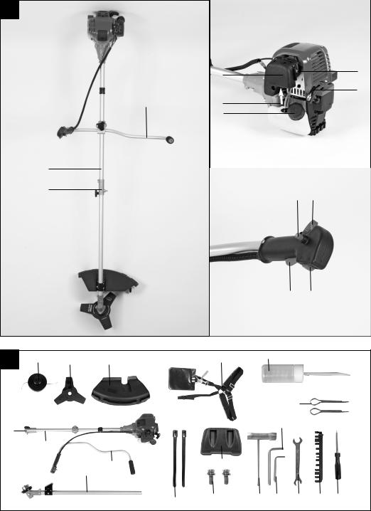
2. Gerätebeschreibung (Abb. 1-14)
1.Verbindungsstück Führungsholm
2.Führungsholm
3.Führungshandgriff
4.Starterleine
5.Choke-Hebel
6.Benzintank
7.Kraftstoffpumpe „Primer“
8.Abdeckung Luftfiltergehäuse
9.Ein-/Aus- Schalter
10.Arretierung Gashebel
11.Gashebel
12.Gashebelsperre
13.Fadenspule mit Schnittfaden
14.Schutzhaube Schnittfaden
15.Schutzhaube Schnittmesser
16.2x Splint
17.Tragegurt
18.Schnittmesser
19.Halterung Führungshandgriff
20.Griffschraube M8
21.Schutzkappe
22.Mitnehmerscheibe
23.Druckplatte
24.Abdeckung Druckplatte
25.Mutter M10 (Linksgewinde)
26.Einfüllflasche
27.Zündkerzenschlüssel
28.Gabelschlüssel 8/10mm
29.Inbusschlüssel 4 mm
30.Inbusschlüssel 5 mm
31.Schraubendreher
32.2x Kabelbinder
33.Stützplatte
34.2x Schraube
35.Luftfilter
36.Zündkerzenstecker
37.Griffschraube M6
38.Öleinfüllschraube
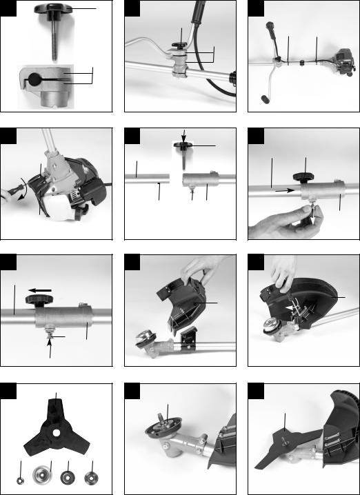
3. Lieferumfang
nÖffnen Sie die Verpackung und nehmen Sie das Gerät vorsichtig aus der Verpackung.
nEntfernen Sie das Verpackungsmaterial sowie
Verpackungs-/ und Transportsicherungen (falls vorhanden).
nÜberprüfen Sie, ob der Lieferumfang vollständig ist.
nKontrollieren Sie das Gerät und die Zubehörteile auf Transportschäden.
nBewahren Sie die Verpackung nach Möglichkeit bis zum Ablauf der Garantiezeit auf.
ACHTUNG
Gerät und Verpackungsmaterial sind kein Kinderspielzeug! Kinder dürfen nicht mit Kunststoffbeuteln, Folien und Kleinteilen spielen! Es besteht Verschluckungsund Erstickungsgefahr!
nBenzinsense
nFührungsholm
nFührungshandgriff
nHalterung Führungshandgriff
n2x Splint
nTragegurt
nGriffschraube M8
nGriffschraube M6
nSchnittmesser
nFadenspule mit Schnittfaden
10
nMitnehmerscheibe
nDruckplatte
nAbdeckung Druckplatte
nMutter M10 (Linksgewinde)
nEinfüllflasche
nZündkerzenschlüssel
nGabelschlüssel 8/10mm
nInbusschlüssel 4 mm
nInbusschlüssel 5 mm
nSchutzhaube für Schnittfaden/Schnittmesser
n2x Kabelbinder
nSchraubendreher
nStützplatte
n2x Schraube
nOriginalbetriebsanweisung
nSicherheitshinweise
4. Bestimmungsgemäße Verwendung
Die Motorsense (Verwendung des Schneidmessers) eignet sich zum Schneiden von leichten Gehölz, starken Unkraut und Unterholz.
Der Motortrimmer (Verwendung der Fadenspule mit Schnittfaden) eignet sich zum Schneiden von Rasen, Grasflächen und leichten Unkraut. Die Einhaltung der vom Hersteller beigefügten Gebrauchsanweisung ist Vorraussetzung für den ordnungsgemäßen
Gebrauch des Gerätes. Jede andere Verwendung, die in dieser Anleitung nicht ausdrücklich zugelassen wird, kann zu Schäden am Gerät führen und eine ernsthafte Gefahr für den Benutzer darstellen.
Beachten Sie unbedingt die Einschränkungen in den Sicherheitshinweisen.
Bitte beachten Sie, dass unsere Geräte bestimmungsgemäß nicht für den gewerblichen, handwerklichen oder industriellen Einsatz konstruiert wurden. Wir übernehmen keine Gewährleistung, wenn das Gerät in Gewerbe-, Handwerksoder Industriebetrieben sowie bei gleichzusetzenden Tätigkeiten eingesetzt wird.
Achtung! Wegen körperlicher Gefährdung des
Benutzers darf die Benzinmotorsense nicht zu folgenden Arbeiten eingesetzt werden: zum Reinigen von Gehwegen und als Häcksler zum Zerkleinern von Baumund Heckenabschnitten. Ferner darf die Benzinmotorsense nicht zum Einebnen von
Bodenerhebungen, wie z.B. Maulwurfshügel verwendet werden. Aus Sicherheitsgründen darf die Benzinmotorsense nicht als Antriebsaggregat für andere Arbeitswerkzeuge und Werkzeugsätze jeglicher Art verwendet werden.
D
Die Maschine darf nur nach ihrer Bestimmung verwendet werden. Jede weitere darüber hinausgehende Verwendung ist nicht bestimmungsgemäß. Für daraus hervorgerufene
Schäden oder Verletzungen aller Art haftet der
Benutzer/Bediener und nicht der Hersteller.
5. Technische Daten
Motortyp |
|
4-Takt-Motor, luftgekühlt |
Motorleistung (max.) |
1 kW/ 1,36 PS |
|
|
|
|
Hubraum |
|
33,5 ccm |
|
|
|
Leerlaufdrehzahl Motor |
2800 min-1 |
|
|
|
|
Max. Drehzahl Motor |
|
|
Sense: |
|
8500 min-1 |
Trimmer: |
|
7500 min-1 |
|
|
|
Zündung |
|
Elektronisch |
|
|
|
Antrieb |
|
Zentrifugalkupplung |
|
|
|
Gewicht (leerer Tank) |
8 kg |
|
|
|
|
Schnittkreis-Faden Ø |
46 cm |
|
|
|
|
Schnittkreis-Messer Ø |
25,5 cm |
|
|
|
|
Fadenlänge |
|
4,0 m |
|
|
|
Faden-Ø |
|
2,5 mm |
|
|
|
Tankinhalt |
|
0,65 l |
|
|
|
Zündkerze |
Torch CMR6A (Champion RY4C) |
|
|
|
|
Geräusch und Vibration
Schalldruckpegel LpA |
96 dB(A) |
Unsicherheit KpA |
3 dB |
Schallleistungspegel LWA |
107 dB(A) |
Unsicherheit KWA |
3 dB |
Tragen Sie einen Gehörschutz.
Die Einwirkung von Lärm kann Gehörverlust bewirken.
Betrieb
Schwingungsemissionswert ah = 5 m/s2
Unsicherheit K = 1,5 m/s2
11

D
Beschränken Sie die Geräuschentwicklung und Vibration auf ein Minimum!
nVerwenden Sie nur einwandfreie Geräte.
nWarten und reinigen Sie das Gerät regelmäßig.
nPassen Sie Ihre Arbeitsweise dem Gerät an.
nÜberlasten Sie das Gerät nicht.
nLassen Sie das Gerät gegebenenfalls
überprüfen.
nSchalten Sie das Gerät aus, wenn es nicht benutzt wird.
nTragen Sie Handschuhe.
6. Vor Inbetriebnahme
6.1 Montage
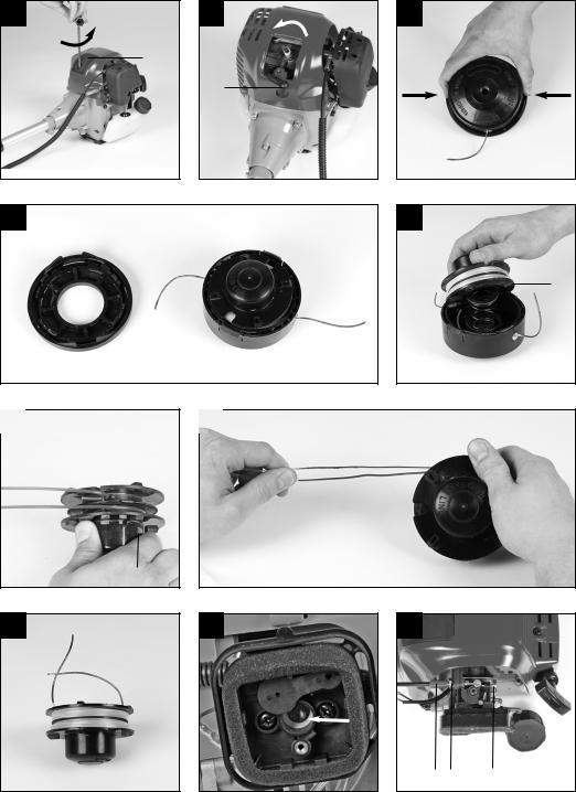
6.1.1Montage des Führungshandgriffes
Montieren Sie den Führungshandgriff wie in den Abbildungen 3a-3c dargestellt. Ziehen Sie die
Schraube erst dann ganz fest, wenn Sie die optimale
Arbeitsposition mit dem Tragegurt eingestellt haben. Der Führungshandgriff sollte wie in Abbildung 1 dargestellt ausgerichtet werden. Die Demontage erfolgt umgekehrt.
6.1.2Montage Führungsholm (Abb. 4a – 4c)
Schieben Sie die Griffschraube (37) in das Verbindungsstück des Führungsholms (1) (Abb.4a).
Verschrauben Sie die Griffschraube locker.
Ziehen Sie nun den Arretierhebel (A) und schieben
Sie vorsichtig den Führungsholm (Abb. 4b/Pos. 2) in das Verbindungsstück des Führungsholmes. Achten
Sie dabei darauf, dass die Antriebswellen im inneren des Führungsholmes ineinander gleiten (gegebenenfalls leicht am Spulenkopf drehen). Die Nase des Arretierhebels (A) muss in das Loch (B) einrasten. Ziehen Sie nun die Griffschraube, wie in Abbildung 4c an. Nach erstmaligen Zusammenbau braucht die Griffschraube nur gelockert und der Hebel betätigt werden um den Führungsholm zu zerlegen.
6.1.3Montage der Messerschutzhaube
Achtung: Beim Arbeiten mit dem Schnittmesser muss die Schnittmesser-Schutzhaube montiert sein. Die Montage der Schnittmesser-Schutzhaube erfolgt wie in den Abbildungen 5a-5b dargestellt.
6.1.4 Montage/Ersetzen des Schnittmessers
Die Montage des Schnittmesser ist auf den Bildern 6a-6h zu sehen. Die Demontage erfolgt in umgekehrter Reihenfolge.
nMitnehmerscheibe (22) auf die Zahnwelle stecken (Abb. 6b)
nSchnittmesser (18) auf der Mitnehmerscheibe arretieren (Abb. 6c)
nDruckplatte (23) über das Gewinde der
Zahnwelle stecken (Abb. 6d)
nAbdeckung Druckplatte (24) aufstecken (Abb. 6e)
nDie Bohrung der Mitnehmerscheibe suchen, mit der darunter liegenden Kerbe überein bringen und mit dem mitgelieferten Inbusschlüssel (29) arretieren um nun die Mutter (25) anzuziehen (Abb. 6f/6g). Achtung: Linksgewinde
nDen Sicherungssplint (16) durch die Bohrung in der Antriebswelle schieben und die Laschen wie in Abbildung 6h um die Welle biegen.
6.1.5Montage der Schnittfadenschutzhaube an der Messerschutzhaube
Achtung: Beim Arbeiten mit dem Schnittfaden muss zusätzlich die Schnittfadenschutzhaube (Abb. 7a/Pos.14) montiert werden.
Die Montage der Schnittfaden-Schutzhaube erfolgt wie in den Abbildungen 7a – 7b dargestellt. An der Unterseite der Schutzhaube befindet sich ein Messer (Abb. 7a/ Pos. F) für die automatische Fadenlängenregulierung. Dieses ist mit einem
Schutz (Abb. 7a/ Pos.G) abgedeckt.
Entfernen Sie diesen Schutz vor Arbeitsbeginn und bringen Sie diesen nach dem Arbeiten wieder an.
6.1.6 Montage/ Ersetzen der Fadenspule
Die Montage der Fadenspule ist auf dem Bildern 7c7d zu sehen. Die Demontage erfolgt umgekehrt.
Die Bohrung der Mitnehmerscheibe suchen, mit der darunter liegenden Kerbe überein bringen und mit dem mitgelieferten Inbusschlüssel (29) arretieren um nun die Fadenspule auf das Gewinde zu schrauben. Achtung: Linksgewinde
6.2 Einstellen der Schnitthöhe
nTragegurt wie in Abbildung 8a-8c dargestellt anlegen.
nDas Gerät am Tragegurt einhaken (Abb. 8d).
nMit den verschiedenen Gurtverstellern am
Tragegurt optimale Arbeitsund Schnittposition einstellen (Abb. 8e).
nUm die optimale Tragegurtlänge festzustellen machen Sie anschließend einige Schwingbewegungen ohne den Motor anzulassen (Abb. 9a).
Der Tragegurt ist mit einem SchnellöffnungsMechanismus ausgestattet. Ziehen Sie, falls es notwendig ist das Gerät schnell abzulegen, an dem
Gurtstück (Abb. 8f).
Achtung: Benutzen Sie den Gurt immer wenn Sie mit dem Gerät arbeiten. Bringen Sie den Gurt an
12

sobald Sie den Motor gestartet haben und er im Leerlauf läuft. Schalten Sie den Motor aus bevor Sie den Tragegurt abnehmen.
Prüfen Sie das Gerät vor jeder Inbetriebnahme auf:
nDichtheit des Treibstoffsystems.
nEinwandfreien Zustand und Vollständigkeit der Schutzeinrichtungen und der Schnittvorrichtung.
nFesten Sitz sämtlicher Verschraubungen.
nLeichtgängigkeit aller beweglichen Teile.
6.3 Kraftstoff einfüllen
Schrauben Sie den Tankdeckel (Abb. 1/Pos. 6) ab und füllen Sie mit Hilfe eines Einfüllstutzens maximal
0,65 l unverbleites Benzin in den Tankbehälter. Achten Sie darauf dass der Tank nicht überfüllt wird und Benzin ausläuft. Trocknen Sie verschüttetes Benzin ab und warten Sie bis sich die Benzindämpfe verflüchtigt haben (Entzündungsgefahr).
Verschließen Sie den Tankdeckel.
6.4 Öl einfüllen
Öffnen Sie die Öleinfüllschraube (Abb. 14a/ Pos. 38) und füllen Sie etwa 0,1 l Motorenöl (15W40) bis zur oberen Markierung (Max.) des Ölmessstabes (Abb.14b) ein.
Achtung! Vor Erstinbetriebnahme muss Motorenöl und Kraftstoff eingefüllt werden.
7. Bedienung
Beachten Sie bitte die gesetzlichen Bestimmungen zur Lärmschutzverordnung, die örtlich unterschiedlich sein können.
Entfernen Sie vor Inbetriebnahme die Schutzkappen vom Schnittmesser (18).
7.1 Starten bei kaltem Motor
Füllen Sie den Tank mit einer angemessenen Menge Benzin.
1.Gerät auf eine harte, ebene Fläche stellen.
2.Kraftstoffpumpe (Primer) (Abb. 1/Pos. 7) 10x drücken.
3.Ein-/ Aus-Schalter (Abb. 1/Pos. 9) auf „I“ schalten.
4.Gashebel feststellen. Hierzu Gashebelsperre
(Abb. 1/Pos. 12) und anschließend Gashebel (Abb. 1/Pos. 11) betätigen und durch gleichzeitiges Drücken der Arretierung (Abb. 1/Pos. 10) den Gashebel feststellen.
5.Choke-Hebel (Abb. 1/Pos. 5) auf „  “ stellen.
6.Das Gerät gut festhalten und die Starterleine (Abb. 1/Pos. 4) bis zum ersten Widerstand herausziehen. Jetzt den Startseilzug 4x rasch anziehen. Das Gerät sollte starten.
D
Achtung: Die Starterleine nicht zurückschleudern lassen. Dies kann zu
Beschädigungen führen.
Ist der Motor gestartet, den Choke-Hebel sofort auf „  “ stellen und das Gerät ca. 10 sek. warmlaufen lassen.
Achtung: Durch den festgestellten Gashebel beginnt das Schnittwerkzeug bei startendem Motor zu arbeiten.
Anschließend Gashebel durch einfaches Betätigen entriegeln.
7. Sollte der Motor nicht starten wiederholen Sie die
Schritte 4-6.
Zur Beachtung: Springt der Motor auch nach mehreren Versuchen nicht an, lesen Sie den Abschnitt „Fehlerbehebung am Motor“.
Zur Beachtung: Ziehen Sie den Startseilzug stets gerade heraus. Wird sie in einem Winkel herausgezogen, entsteht Reibung an der Öse. Durch diese Reibung wird die Schnur durchgescheuert und nutzt sich schneller ab. Halten Sie stets den
Anlassergriff, wenn sich die Schnur wieder einzieht.
Lassen Sie die Schnur nie aus dem ausgezogenen Zustand zurückschnellen.
7.2 Starten bei warmem Motor
(Das Gerät stand für weniger als 15-20min still)
1.Gerät auf harte, ebene Fläche stellen.
2.Ein-/Aus-Schalter auf „I“ schalten.
3.Gashebel feststellen (analog „Starten bei kaltem
Motor“).
4.Gerät gut festhalten und die Starterleine bis zum ersten Widerstand herausziehen. Jetzt die
Starterleine rasch anziehen. Das Gerät sollte nach 1-2 Zügen starten. Falls die Maschine nach
6 Zügen immer noch nicht startet wiederholen Sie die Schritte 1-7 unter kalten Motor starten.
7.3 Motor abstellen
Not-Aus Schrittfolge:
Falls es notwendig ist, die Maschine sofort anzuhalten, stellen Sie hierzu den Ein-/Aus-Schalter auf „Stop“ bzw. „0“
Normale Schrittfolge:
Lassen Sie den Gashebel los und warten Sie bis der Motor in Leerlaufgeschwindigkeit übergegangen ist.
Stellen Sie dann den Ein-/ Aus-Schalter auf „Stop“ bzw. „0“.
13

D
7.4 Arbeitshinweise
Trainieren Sie vor Einsatz des Gerätes sämtliche Arbeitstechniken bei abgestelltem Motor.
Verlängerung des Schnittfadens
Warnung! Benutzen Sie keinen Metalldraht oder kunststoffumhüllten Metalldraht irgendeiner Art in der Fadenspule. Dies kann zu schweren Verletzungen beim Benutzer führen.
Zur Verlängerung des Schnittfadens, lassen Sie den
Motor auf Vollgas laufen und tippen Sie die Fadenspule auf den Boden. Der Faden wird automatisch verlängert. Das Messer am Schutzschild kürzt den Faden auf die zulässige Länge (Abb. 9b).
Vorsicht: Entfernen Sie regelmäßig alle Rasenund Unkrautreste um ein Überhitzen des Schaftrohrs zu vermeiden. Rasen-/ Gras-/Unkrautreste verfangen sich unterhalb des Schutzschilds (Abb. 9c), dies verhindert eine ausreichende Kühlung des
Schaftrohrs. Entfernen Sie die Reste vorsichtig mit einem Schraubenzieher oder dergleichen.
Verschiedene Schnittverfahren
Ist das Gerät richtig montiert, schneidet es Unkraut und hohes Gras an schwer zugänglichen Stellen, wie z.B. entlang von Zäunen, Mauern und Fundamenten sowie um Bäume herum. Es lässt sich auch für „Abmäharbeiten“ einsetzen, um Vegetation zur besseren Vorbereitung eines Gartens oder zum Ausputzen eines bestimmten Bereiches bodennah zu entfernen.
Zur Beachtung: Auch bei sorgfältiger Anwendung hat das Schneiden an Fundamenten, Steinoder Betonmauern usw. eine über dem Normalen liegende Abnutzung des Fadens zur Folge.
Trimmen/ Mähen
Schwingen Sie den Trimmer in sichelartiger Bewegung von Seite zu Seite. Halten Sie die Fadenspule stets parallel zum Boden. Überprüfen
Sie das Gelände und legen Sie die gewünschte Schnitthöhe fest. Führen und halten Sie die
Fadenspule in der gewünschten Höhe, zwecks gleichmässigem Schnitt (Abb. 9d).
Niedriges Trimmen
Halten Sie den Trimmer mit einer leichten Neigung genau vor sich, so dass sich die Unterseite der Fadenspule über dem Boden befindet und der Faden die richtige Schnittstelle trifft. Schneiden Sie immer von sich weg. Ziehen Sie den Trimmer nicht zu sich hin.
Schneiden an Zaun/ Fundament
Nähern Sie sich beim Schneiden langsam Maschendrahtzäunen, Lattenzäunen, Natursteinmauern und Fundamenten um nah daran zu schneiden, ohne jedoch mit dem Faden gegen das Hindernis zu schlagen. Kommt der Faden z.B. mit Steinen, Steinmauern oder Fundamenten in Berührung, nutzt er sich ab oder franst aus. Schlägt der Faden gegen Zaungeflecht, bricht er ab.
Trimmen um Bäume
Trimmen Sie um Baumstämme, nähern Sie sich langsam, damit der Faden die Rinde nicht berührt. Gehen Sie um den Baum herum, und schneiden Sie dabei von links nach rechts. Nähern Sie sich Gras oder Unkraut mit der Spitze des Fadens, und kippen
Sie die Fadenspule leicht nach vorn. Warnung: Seien Sie überaus vorsichtig bei
Abmäharbeiten. Halten Sie bei solchen Arbeiten einen Abstand von 30 Metern zwischen sich und anderen Personen oder Tieren ein.
Abmähen
Beim Abmähen erfassen Sie die gesamte Vegetation bis zum Grund. Dazu neigen Sie die Fadenspule im
30 Grad Winkel nach rechts. Stellen Sie den
Handgriff in die gewünschte Position. Beachten Sie die erhöhte Verletzungsgefahr des Benutzers,
Zuschauer und Tiere, sowie die Gefahr der
Sachbeschädigung durch weggeschleuderte Objekte (z.B. Steine) (Abb. 9e).
Warnung: Entfernen Sie mit dem Gerät keine
Gegenstände von Fußwegen usw.!
Das Gerät ist ein kraftvolles Werkzeug, und kleine
Steine oder andere Gegenstände können 15 Meter und mehr weggeschleudert werden und zu Verletzungen oder Beschädigungen an Autos,
Häusern und Fenstern führen.
Sägen
Das Gerät ist nicht zum Sägen geeignet.
Verklemmen
Sollte das Schnittmesser wegen zu dichter
Vegetation blockieren stellen Sie unverzüglich den Motor ab. Befreien Sie das Gerät von Gras und Gestrüpp bevor Sie es erneut in Betrieb nehmen.
Vermeiden von Rückschlag
Beim Arbeiten mit dem Schnittmesser besteht die Gefahr des Rückschlages wenn dieses auf feste Hindernisse (Baumstamm, Ast, Baumstumpf, Stein oder dergleichen) trifft. Das Gerät wird dabei gegen die Drehrichtung des Werkzeugs zurückgeschleudert. Dies kann zum Verlust der Kontrolle über das Gerät führen. Benutzen Sie das Schnittmesser nicht
14

in der Nähe von Zäunen, Metallpfosten, Grenzsteinen oder Fundamenten.
Zum Schneiden von dichten Stängeln positionieren
Sie diese wie in Abb. 9f dargestellt um Rückschläge zu vermeiden.
8.Reinigung, Wartung und Ersatzteilbestellung
Schalten Sie das Gerät vor Wartungsarbeiten immer aus und ziehen Sie den Zündkerzenstecker ab.
8.1 Ersetzen von Fadenspule/Schnittfaden
1.Die Fadenspule (13) wie in Abs. 6.1.6 beschrieben demontieren. Die Spule zusammendrücken (Abb. 12a) und eine Gehäusehälfte abnehmen (Abb. 12b).
2.Spulenteller (K) aus dem Fadenspulen-Gehäuse entnehmen (Abb. 12c).
3.Evtl. noch vorhandenen Schnittfaden entfernen.
4.Die 2 Schnittfaden jeweils zu einem Hacken formen und in die Öse in dem Spulenteller wie in
Abbildung 12d einhängen. Die 2 Faden müssen um 180° versetzt eingehängt werden.
5.Faden unter Spannung gegen den Uhrzeigersinn aufwickeln. Der Spulenteiler trennt dabei die beiden Hälften des Nylonfadens. (Abb. 12e)
6.Die letzten 15cm der beiden Fadenenden in die gegenüberliegenden Fadenhalter des
Spulentellers einhaken. (Abb. 12f)
7.Die beiden Fadenenden durch die Metallösen im
Fadenspulen-Gehäuse führen (Abb. 12c).
8.Spulenteller in das Fadenspulen-Gehäuse drücken.
9.Kurz und kräftig an beiden Fadenenden ziehen um diese aus den Fadenhaltern der Fadenspule zu lösen.
10.Überschüssigen Faden auf etwa 13cm zurückschneiden. Das verringert die Belastung auf den Motor während des Startens und Aufwärmens.
11.Fadenspule wieder montieren Siehe Punkt 6.1.6 Wird die komplette Fadenspule erneuert sind die Punkte 3-6 zu überspringen.
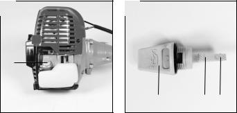
8.2 Wartung des Luftfilters
Verschmutzte Luftfilter verringern die Motorleistung durch zu geringe Luftzufuhr zum Vergaser. Regelmäßige Kontrolle ist daher unerlässlich. Der
Luftfilter (35) sollte alle 25 Betriebsstunden kontrolliert werden und bei Bedarf gereinigt werden.
Bei sehr staubiger Luft ist der Luftfilter häufiger zu überprüfen.
1. Entfernen Sie den Luftfilterdeckel (Abb. 10a)
D
2.Entnehmen Sie den Luftfilter (Abb. 10b/10c)
3.Reinigen Sie den Luftfilter durch ausklopfen oder ausblasen.
4.Der Zusammenbau erfolgt in umgekehrter
Reihenfolge.
Achtung: Luftfilter nie mit Benzin oder brennbaren Lösungsmitteln reinigen.
8.3 Wartung der Zündkerze
Zündkerzenfunkenstrecke = 0,6mm. Ziehen Sie die Zündkerze mit 12 bis 15 Nm an. Überprüfen Sie die Zündkerze erstmals nach 10 Betriebsstunden auf Verschmutzung und reinigen Sie diese gegebenenfalls mit einer Kupferdrahtbürste.
Danach die Zündkerze alle 50 Betriebsstunden warten.
1.Demontieren Sie die Schutzkappe (Abb.11a Pos. 21) mit einem Schraubendreher.
2.Ziehen Sie den Zündkerzenstecker (Abb. 11b) ab.
3.Entfernen Sie die Zündkerze (Abb. 11b) mit dem beiliegenden Zündkerzenschlüssel (27).
4.Der Zusammenbau erfolgt in umgekehrter
Reihenfolge.
8.4 Schleifen des Schutzhaubenmessers
Das Schutzhaubenmesser kann mit der Zeit stumpf werden. Sollten Sie dies feststellen, lösen Sie die
Schrauben mit denen das Schutzhaubenmesser an der Schutzhaube befestigt ist. Befestigen Sie das Messer in einem Schraubstock. Schleifen Sie das
Messer mit einer Flachfeile und achten Sie darauf, den Winkel der Schnittkante beizubehalten. Feilen Sie nur in eine Richtung.
8.5 Vergaser Einstellungen
Achtung! Einstellungen am Vergaser dürfen nur durch autorisierten Kundendienst vorgenommen werden. Zu allen Arbeiten am Vergaser muss zuerst die Luftfilterabdeckung wie in Abbildung 10a-10c gezeigt demontiert werden.
Einstellen des Gasseilzuges:
Sollte die Maximaldrehzahl des Geräts mit der Zeit nicht mehr erreicht werden und sämtliche anderen
Ursachen nach Abschnitt 11 Fehlerbehebung ausgeschlossen sein, könnte eine Einstellung des Gasseilzuges erforderlich sein.
Überprüfen Sie hierfür zunächst ob der Vergaser bei voll durchgedrücktem Gasgriff ganz öffnet. Dies ist der Fall wenn der Vergaserschieber (Abb. 13a) bei voll betätigtem Gas vollständig geöffnet ist. Abbildung 13a zeigt die korrekte Einstellung. Sollte der Vergaserschieber nicht vollständig geöffnet sein, ist eine Nachjustierung notwendig.
15

D
Um den Gasseilzug nachzustellen sind folgende Schritte erforderlich:
nLösen Sie die Kontermutter (Abb. 13b/Pos. C) einige Umdrehungen.
nDrehen Sie die Verstellschraube (Abb. 13b/Pos.
D)heraus, bis der Vergaserschieber bei voll betätigtem Gas, wie in Abbildung 13a gezeigt, vollständig geöffnet ist.
nZiehen Sie die Kontermutter wieder fest.
Einstellen des Standgases:
Achtung! Standgas bei warmen Betriebszustand einstellen.
Sollte das Gerät bei nicht betätigtem Gashebel ausgehen und sämtliche anderen Ursachen nach Abschnitt 11 Fehlerbehebung ausgeschlossen sein, ist ein Nachjustieren des Standgases notwendig. Drehen Sie hierzu die Standgasschraube (Abb. 13b/
Pos. E) im Uhrzeigersinn bis das Gerät im Leerlauf sicher läuft. Sollte das Standgas so hoch sein, dass sich das Schnittwerkzeug mitdreht, muss dies durch Linksdrehen der Standgasschraube soweit verringert werden bis sich das Schnittwerkzeug nicht mehr mitdreht.
8.6 Ölwechsel, Ölstand prüfen (vor jedem Gebrauch)
Der Motorölwechsel sollte bei betriebswarmen Motor durchgeführt werden. Beachten Sie hierzu auch die
Service-Informationen.
nHalten Sie zum Ölwechsel einen geeigneten Behälter bereit, der nicht ausläuft.
nÖleinfüllschraube (Abb. 14a-14b/ Pos. 38) öffnen.
nDas Altöl durch Kippen des Motors in einen geeigneten Auffangbehälter ablassen.
nMotorenöl (15W40) bis zur oberen Markierung (Max.) des Ölmessstabes (Abb.14b) einfüllen.
nEntsorgen Sie das Altöl ordnungsgemäß. Geben
Sie Ihr Altöl an einer Sammelstelle ab: Die meisten Tankstellen, Reparaturwerkstätten oder
Wertstoffhöfe nehmen Altöl gebührenfrei zurück. Vermischen Sie keine anderen Substanzen wie z.B. Antifrostmittel oder Getriebeflüssigkeit mit dem Altöl. Bewahren Sie es außerhalb der Reichweite von Kindern und Zündquellen auf.
8.7 Umweltschutz
Verschmutztes Wartungsmaterial und Betriebsstoffe in einer dafür vorgesehenen Sammelstelle abgeben. Verpackungsmaterial, Metall und Kunststoffe dem
Recycling zuführen.
8.8 Ersatzteilbestellung
Bei der Ersatzteilbestellung sollten folgende
Angaben gemacht werden;
nTyp des Gerätes
nArtikelnummer des Gerätes
nIdent-Nummer des Gerätes
nErsatzteilnummer des erforderlichen Ersatzteils
Aktuelle Preise und Infos finden Sie unter www.isc-gmbh.info
9. Lagerung und Transport
9.1 Lagerung
Vorsicht: Verstauen Sie das Gerät nie länger als 30 Tage, ohne folgende Schritte zu durchlaufen.
Verstauen des Gerätes
Wenn Sie das Gerät länger als 30 Tage verstauen, muss sie hierfür hergerichtet werden. Andernfalls verdunstet der im Vergaser befindliche, restliche Treibstoff und lässt einen gummiartigen Bodensatz zurück. Dies könnte den Start erschweren und teure
Reparaturarbeiten zur Folge haben.
1.Nehmen Sie die Treibstofftankkappe langsam ab, um eventuellen Druck im Tank abzulassen. Entleeren Sie vorsichtig den Tank.
2.Starten Sie den Motor und lassen Sie ihn laufen, bis die Säge anhält, um den Treibstoff aus dem
Vergaser zu entfernen.
3.Lassen Sie den Motor abkühlen (ca. 5 Minuten).
4.Entfernen Sie die Zündkerze (siehe 8.3)
5.Geben Sie 1 Teelöffel sauberes 2-Takt-Öl in die Verbrennungskammer. Ziehen Sie mehrere Male langsam an der Starterleine, um die internen Komponenten zu beschichten. Setzen Sie die
Zündkerze wieder ein.
Hinweis: Verstauen Sie das Gerät an einem trockenen Ort und weit entfernt von möglichen
Entzündungsquellen, z.B. Ofen, Heißwasserboiler mit Gas, Gastrockner, etc.
Erneutes Inbetriebnehmen
1.Entfernen Sie die Zündkerze (siehe 8.3).
2.Ziehen Sie rasch an der Starterleine, um überschüssiges Öl aus der Verbrennungskammer zu entfernen.
3.Reinigen Sie die Zündkerze und achten Sie auf den richtigen Elektrodenabstand an der
Zündkerze; oder setzen Sie eine neue Zündkerze mit richtigem Elektrodenabstand ein.
4.Bereiten Sie das Gerät für den Betrieb vor
5.Füllen Sie den Tank mit der richtigen Treibstoff-/ Ölmischung auf. Siehe Abschnitt Treibstoff und Öl.
16

D
9.2 Transport
Wenn Sie das Gerät transportieren möchten entleeren Sie den Benzintank wie im Kapitel
„Lagerung“ erklärt. Reinigen Sie das Gerät mit einer
Bürste oder einem Handfeger von grobem Schmutz. Demontieren Sie den Führungshandgriff wie unter Punkt 6.1.1 erklärt.
10. Entsorgung und Wiederverwertung
Das Gerät befindet sich in einer Verpackung um
Transportschäden zu verhindern. Diese Verpackung ist Rohstoff und ist somit wieder verwendbar oder kann dem Rohstoffkreislauf zurückgeführt werden. Das Gerät und dessen Zubehör bestehen aus verschiedenen Materialien, wie z.B. Metall und
Kunststoffe. Führen Sie defekte Bauteile der
Sondermüllentsorgung zu. Fragen Sie im Fachgeschäft oder in der Gemeindeverwaltung nach!
17

D
11. Fehlerbehebung
Störung |
Mögliche Ursache |
Störungsbehebung |
||
Das Gerät springt nicht an. |
Fehlerhaftes Vorgehen beim |
Folgen Sie den Anweisungen zum |
||
|
Starten. |
Starten |
||
|
Verrußte oder feuchte Zündkerze |
Zündkerze reinigen oder durch |
||
|
|
neue ersetzen. |
||
|
Falsche Vergasereinstellung |
Autorisierten Kundendienst |
||
|
|
aufsuchen, oder das Gerät an die |
||
|
|
ISC-GmbH senden. |
||
|
|
|
|
|
Das Gerät springt an, hat aber nicht |
Falsche Einstellung des |
Chokehebel auf „ |
|
“ stellen. |
|
||||
die volle Leistung. |
Chokehebels |
|
|
|
|
Verschmutzter Luftfilter |
Luffilter reinigen |
||
|
Falsche Vergasereinstellung |
Autorisierten Kundendienst |
||
|
|
aufsuchen, oder das Gerät an die |
||
|
|
ISC-GmbH senden. |
||
Der Motor läuft unregelmäßig |
Falscher Elektrodenabstand der |
Zündkerze reinigen und |
||
|
Zündkerze |
Elektrodenabstand einstellen oder |
||
|
|
neue Zündkerze einsetzen. |
||
|
Falsche Vergasereinstellung |
Autorisierten Kundendienst |
||
|
|
aufsuchen, oder das Gerät an die |
||
|
|
ISC-GmbH senden. |
||
Motor raucht übermäßig |
Falsche Vergasereinstellung |
Autorisierten Kundendienst |
||
|
|
aufsuchen, oder das Gerät an die |
||
|
|
ISC-GmbH senden. |
||
|
|
|
|
|
18

GB
Table of contents
1.Safety information
2.Layout
3.Items supplied
4.Intended use
5.Technical data
6.Before starting the equipment
7.Operation
8.Cleaning, maintenance and ordering of spare parts
9.Storage and transport
10.Disposal and recycling
11.Troubleshooting
19

GB
Important.
When using the equipment, a few safety precautions must be observed to avoid injuries and damage. Please read the complete operating instructions and safety information with due care. Keep these operating instructions in a safe place so that the information is available at all times. If you give the equipment to any other person, hand over these operating instructions and the safety information as well. We cannot accept any liability for damage or accidents which arise due to a failure to follow these instructions and the safety information.
1. Safety information
Please refer to the booklet included in delivery for the safety information.
CAUTION
Read all the safety regulations and instructions.
Any errors made in following the safety information and instructions set out below may result in an electric shock, fire and/or serious injury.
Keep all safety information and instructions in a safe place for future use.
Safety devices
When working with the equipment, the appropriate plastic guard hood for cutting blade mode or cutting line mode must be fitted to prevent objects being thrown out by the equipment. The integrated blade in the cutting line guard hood automatically cuts the line to the optimum length.
2. Layout (Fig. 1-14)
1.Connecting piece for long handle
2.Long handle
3.Steady grip
4.Starter cable
5.Choke lever
6.Petrol tank
7.Fuel pump “primer”
8.Ai r filter housing cover
9.On/Off switch
10.Throttle lever lock
11.Throttle lever
12.Throttle lock
13.Line spool with cutting line
14.Cutting line guard hood
15.Cutting blade guard hood
16.Cotter pin (2x)
17.Carrying strap
18.Cutting blade
19.Holder for steady grip
20.Handle screw M8
21.Protective cap
22.Carrier plate
23.Pressure plate
24.Pressure plate cover
25.Nut M10 (left-hand thread)
26.Filling bottle
27.Spark plug wrench
28.Open-ended spanner 8/10 mm
29.Allen key size 4 mm
30.Allen key size 5 mm
31.Screwdriver
32.Cable tie (2x)
33.Support plate
34.Screw (2x)
35.Air filter
36.Spark plug boot
37.Handle screw M6
38.Oil filler screw
3. Items supplied
nOpen the packaging and take out the equipment with care.
nRemove the packaging material and any packaging and/or transportation braces (if available).
nCheck to see if all items are supplied.
nInspect the equipment and accessories for transport damage.
nIf possible, please keep the packaging until the end of the guarantee period.
IMPORTANT
The equipment and packaging material are not toys. Do not let children play with plastic bags, foils or small parts.
There is a danger of swallowing or suffocating!
nPetrol power scythe
nLong handle
nSteady grip
nHolder for steady grip
nCotter pin (2x)
nCarrying strap
nHandle screw M8
nHandle screw M6
nCutting blade
nLine spool with cutting line
nCarrier plate
nPressure plate
nPressure plate cover
nNut M10 (left-hand thread)
20
nFilling bottle
nSpark plug wrench
nOpen-ended spanner 8/10 mm
nAllen key size 4 mm
nAllen key size 5 mm
nGuard hood for cutting line/cutting blade
nCable tie (2x)
nScrewdriver
nSupport plate
nScrew (2x)
nOriginal operating instructions
nSafety information
4. Intended use
The equipment is designed for cutting lawns and grassed areas. The operating instructions as supplied by the manufacturer must be kept and referred to in order to ensure that the equipment is properly used and maintained. Any use which is not expressly permitted in the manual may result in damage to the equipment and place the user in serious danger. Be sure to observe the restrictions in the safety instructions.
Please note that our equipment has not been designed for use in commercial, trade or industrial applications. Our warranty will be voided if the equipment is used in commercial, trade or industrial businesses or for equivalent purposes.
Important. Due to the high risk of bodily injury to the user, the petrol power scythe must not be used to carry out the following work: to clean dirt and debris off walkways, or to chop up tree or hedge clippings. Moreover, the petrol power scythe may not be used to level out high areas such as molehills. For safety reasons, the petrol power scythe may not be used as a drive unit for other work tools or toolkits of any kind.
The equipment is to be used only for its prescribed purpose. Any other use is deemed to be a case of misuse. The user/operator and not the manufacturer will be liable for any damage or injuries of any kind caused as a result of this.
GB
5. Technical data
Engine type
4-stroke engine, air-cooled, chrome cylinder
Engine power (max.) |
1 kW (1.36 HP) |
|
Displacement |
|
33.5 ccm |
Idle speed of engine |
2,800 min-1 |
|
Max. torque engine |
|
|
Scythe: |
|
8,500 min-1 |
Trimmer: |
|
7,500 min-1 |
Ignition |
|
Electronic |
Drive |
|
Centrifugal clutch |
Weight (with empty tank) |
4 kg |
|
Cutting line diameter |
46 cm |
|
Cutting circle diameter of blade |
25,5 cm |
|
Cutting line length |
|
8 m |
Cutting line diameter: |
2.5 mm |
|
Tank capacity |
|
0.65 l |
Spark plug |
Torch CMR6A (Champion RY4C) |
|
Sound and vibration
Sound pressure level LpA |
96 dB(A) |
Uncertainty KpA |
3 dB |
Sound power level LWA |
107 dB(A) |
Uncertainty KWA |
3 dB |
Wear ear-muffs.
The impact of noise can cause damage to hearing.
Functions
Vibration emission value ah = 5 m/s2
K uncertainty = 1.5 m/s2
Reduce noise generation and vibration to a minimum!
nUse only equipment that is in perfect condition.
nMaintain and clean the equipment regularly.
nAdopt your way of working to the equipment.
nDo not overload the equipment.
nHave the equipment checked if necessary.
nSwitch off the equipment when not in use.
nWear gloves.
21

6.1.5Fitting the cutting line guard hood to the blade guard hood
Important: The cutting line guard hood must be additionally fitted if you want to work with the cutting line (Fig. 7a/Item 14).
The guard hood for the cutting line must be installed as shown in Figures 7a – 7b. A blade (Fig. 7a/ Item F) on the underside of the guard hood automatically cuts the cutting line to the optimum length. This is covered by a guard (Fig. 7a/Item G).
Remove the guard before you start working and replace it when you have finished working.
6.1.6Fitting/Replacing the line spool
The fitting of the line spool is shown on Figure 7c-7d. To dismantle, proceed in reverse order.
Look for the hole in the carrier plate, line up with the notch beneath it, lock with the supplied Allen key (29), and screw the line spool onto the thread. Important: Left-hand thread
6.2 Setting the cutting height
nFit the carrying strap as shown in Figures 8a-8c.
nHook the equipment to the carrying belt (Fig. 8d).
nAdjust the perfect working and cutting position using the various strap adjusters on the carrying strap (Fig. 8e).
nIn order to establish the optimum length of the carrying strap, you should then make a few swinging movements without starting the engine (Fig. 9a).
The carrying strap is fitted with a quick-release mechanism. Pull the strap (Fig. 8f) if you need to put down the equipment quickly.
Important: Always use the strap when working with the equipment. Attach the strap as soon as you have started the engine and it is running in idle mode.
Switch off the engine before you take off the carrying strap.
Check the equipment for the following each time before use:
nThat there are no leaks in the fuel system.
nThat the equipment is in perfect condition and that the safety devices and cutting devices are complete.
nThat all screws are securely fastened.
nThat all moving parts move smoothly.

6.3 Topping up with fuel
Unscrew the tank cover (Fig. 1/Item 6) and fill in up to
0.65 liters of unleaded petrol using a filler neck. Make sure that you do not overfill the tank and spill petrol. (If you do spill any petrol, wipe it up and wait until the vapors have evaporated (danger of ignition.)
Close the tank cap.
6.4 Topping up with oil
Open the oil filler screw (Fig. 14a/Item 38) and fill in approx. 0.1 liters of engine oil (15W40) up to the top mark (Max.) on the oil dipstick (Fig. 14b).
Important. The equipment must be filled with engine oil and fuel before it is started.
7. Operation
Please note that the statutory regulations governing noise abatement may differ from town to town. Before starting up the equipment remove the protective caps from the cutting blade (18).
7.1 Starting the engine when cold
Fill an adequate amount of petrol into the tank.
1.Set the equipment down on a hard, level surface.
2.Press the fuel pump (primer) (Fig. 1/Item 7) 10 times.
3.Move the ON/OFF switch (Fig. 1/Item 9) to “I”
4.Secure the throttle lever. To do this, press the throttle lever lock (Fig. 1/Item 12) and then press the throttle lever (Fig. 1/Item 11) and lock the throttle lever by pressing the lock (Fig. 1/Item 10) at the same time.
5.Set the choke lever (Fig. 1/Item 5) to “  ”.
”.
6.Hold the equipment firmly and pull out the starter cable (Fig. 1/Item 4) until you feel it start to resist. Then tug sharply on the starter cable 4 times. The equipment should start.
Important: Never allow the starter cable to snap back. This may damage the equipment.
Once the engine has started, move the choke lever immediately to “  ” and allow the equipment to warm up for approx. 10 seconds.
Important: Since the throttle lever is secured, the cutting tool starts to operate when the engine is started.
Then release the throttle lever by actuating it once.
7.If the engine does not start up, repeat steps 4-6 above.
Please note: If the engine does not start up even after several attempts, read the section “Engine Troubleshooting”. Please note: Always pull the starter cord out in a straight line. If it is pulled out at an angle,
GB
then friction will occur on the eyelet. As a result of this friction, the cable will become frayed and will wear away faster. Always hold the starter handle when the cable retracts. Never allow the cable to snap back when it has been pulled out.
7.2 Starting the engine when warm
(The equipment has been idle for less than 15-20 min.)
1.Set the equipment down on a hard, level surface.
2.Switch the ON/OFF switch to “I”.
3.Secure the throttle lever (in the same way as described in “Starting the engine when cold”).
4.Hold the equipment firmly and pull out the starter cable until you feel it start to resist. Then tug sharply on the starter cable. The equipment should start after 1-2 tugs. If the equipment does not start after 6 pulls, repeat steps 1 – 7 of the procedure for starting the engine from cold.
7.3 Switching off the engine
Emergency Stop procedure:
If it becomes necessary to stop the equipment immediately, set the ON/OFF switch to “Stop” or “0”
Normal procedure:
Let go of the throttle lever and wait until the engine has changed to idling speed. Then set the ON/OFF switch to “Stop” or “0”.
7.4 Practical tips
Practice all operating techniques with the engine switched off before you start to use the equipment.
Extending the cutting line
Warning! Do not use any kind of metal wire or metal wire encased in plastic in the line spool. This may cause serious injuries to the user.
To extend the cutting line run the engine at full speed and tap the line spool on the ground. This will automatically extend the line. The blade on the safety shield will cut the line to the appropriate length (Fig.
9b).
Important: Remove all grass and weed remains at regular intervals to prevent the shaft tube overheating. Grass and weed remains become trapped under the safety shield (Fig. 9c) and they prevent the shaft tube receiving adequate ventilation. Remove the remains carefully using a screwdriver or the like.
23

GB
Different cutting methods
If the equipment is correctly assembled it will cut weeds and long grass in places with difficult access, for example along fences, walls and foundations and also around trees. It can also be used for mowing work to remove vegetation to allow the better preparation of a garden or to clear a certain area down to the soil.
Please note: Even if it is used carefully, cutting around foundations, stone or concrete walls, etc. will result in the line suffering above normal wear.
Trimming/mowing
Swing the trimmer from side to side in a scything motion. Always keep the line spool parallel to the ground. Check the site and decide what cutting height you require. Guide and hold the line spool at the required height to ensure that you cut evenly (Fig. 9d).
Low trimming
Hold the trimmer right in front of you at a slight angle so that the underside of the line spool is above the ground and the line strikes the correct target. Always cut away from yourself. Never draw the trimmer towards yourself.
Cutting along fences/foundations
When cutting approach wire mesh fences, lath fences, natural stone walls and foundations slowly so that you can cut close to them without striking the obstacle with the line. If, for example, the line strikes stones, stone walls or foundations, it will wear or fray. If the line strikes wire fencing it will break.
Trimming around trees
When trimming around tree trunks, approach slowly so that the line does not strike the bark. Walk around the tree, cutting from left to right. Approach grass or weeds with the tip of the line and tilt the line spool forwards slightly.
Warning: Take extreme care during mowing work.
When doing such work keep a distance of 30 meters between yourself and other people or animals.
Mowing
For mowing you want to cut all the vegetation down to the ground. To do this, set the line spool at an angle of 30° to the right. Place the handle in the required position. Remember the increased risk of injury to the user, watchers and animals and the danger of damaging other items due to objects (for example stones) being thrown out (Fig. 9e).
Warning: Do not remove any objects from footpaths, etc. using the equipment.
The equipment is a powerful tool and can throw small stones and other objects a distance of 15 meters or more, causing injuries and damage to cars, houses and windows.
Sawing
The equipment is not suitable for sawing.
Jamming
If the cutting blade jams as a result of attempting to cut vegetation that is too dense, switch off the engine immediately. Remove the grass and scrub from the equipment before you restart it.
Preventing recoil
When you work with the blade there is a risk of recoil if it strikes solid objects such as tree trunks, branches, tree stumps, stones or the like. This will throw the equipment backwards in the direction opposite to the rotation of the tool. This can cause you to lose control of the equipment. Do not use the blade near fences, metal posts, boundary stones or foundations.
For cutting dense stalks, position it as shown in Figure
9f to prevent recoil.
8.Cleaning, maintenance and ordering of spare parts
Always switch off the equipment and pull out the spark boot plug before carrying out any maintenance work.
8.1 Replacing the line spool/cutting line
1.Dismantle the line spool (13) as described in section 6.1.6. Press the spool together (Fig. 12a) and remove one half of the housing (Fig. 12b).
2.Take the spool plate (K) out of the line spool housing (Fig. 12c).
3.Remove any remaining cutting line.
4.Form each of the 2 cutting lines into a hook and hang into the eyelet in the spool plate as shown in Figure 12d. The 2 lines must be hung in so that they are offset by 180°.
5.Wind the line onto the spool counter-clockwise and under tension. The spool splitter will separate the two halves of the nylon line. (Fig. 12e)
6.Hook the last 15cm of the two ends of the line onto the opposite lying line holders of the spool plate. (Fig. 12f)
6.Thread the two ends of the line through the metal eyelets in the line spool housing (Fig. 12c).
7.Press the spool plate into the line spool housing.
24

8.Pull the two line ends sharply to release them from the line holders in the line spool.
9.Cut the excess line to a length of around 13cm.
This will reduce the load on the engine when starting and warming up.
10.Refit the line spool (see section 6.1.6).
11.If you are replacing the complete line spool, skip points 3-6.
8.2 Servicing the air filter
Soiled air filters reduce the engine output by supply too little air to the carburetor. Regular checks are therefore essential. The air filter (35) should be checked after every 25 hours of use and cleaned if necessary. If the air contains a lot of dust, the air filter should be checked more frequently.
1.Remove the air filter cover (Fig. 10a).
2.Remove the air filter (Fig. 10b/10c)
3.Clean the air filter by tapping it or blowing it.
4.Assemble in reverse order.
Important: Never clean the air filter with petrol or inflammable solvents.
8.3 Maintenance of the spark plug
Spark plug sparking gap = 0.6mm. Tighten the spark plug with a torque of 12 to 15 Nm. Check the spark plug for dirt and grime after 10 hours of operation and if necessary clean it with a copper wire brush.
Thereafter service the spark plug after every 50 hours of operation.
1.Dismantle the protective cap (Fig. 11a/Item 21) using a screwdriver.
2.Pull off the spark boot plug (Fig. 11b).
3.Remove the spark plug (Fig. 11b) with the supplied spark plug wrench (27).
4.Assemble in reverse order.
8.4 Grinding the safety hood blade
The safety hood blade can become blunt over time.
When you notice this, undo the two screws holding the safety hood blade to the safety hood. Clamp the blade in a vise. Sharpen the blade with a flat file and make sure that the angle of the cutting edge is not altered in the process. File in one direction only.
8.5 Carburetor settings
Important. Settings on the carburetor may only be made by authorized customer service personnel. The air filter cover must be removed before any work on the carburetor, as shown in Figures 10a and 10c.
GB
Setting the throttle cable
If the maximum speed of the equipment falls over time and you have ruled out all the other causes listed in section 11 Troubleshooting, it may be necessary to adjust the throttle cable.
First of all check whether the carburetor opens fully when the throttle handle is pressed fully. This is the case if the carburetor slide (Fig. 13a) is completely opened when the throttle is fully activated.
Figure 13a shows the correct setting. If the carburetor slide is not completely open, it must be adjusted. The following work is required to adjust the throttle cable:
nUndo the lock nut (Fig. 13b/Item C) a few turns.
nUndo the adjusting screw (Fig. 13b/Item D) until the carburetor slide is completely open when the throttle is fully activated, as shown in Figure 13a.
nRetighten the lock nut.
Setting the idling speed
Important. Set the idling speed when the equipment is warm.
If the engine stalls when the throttle is not pressed and you have ruled out all the other causes listed in section 11 Troubleshooting, the idling speed must be adjusted. To do this turn the idling speed screw (Fig. 13b/Item E) clockwise until the equipment runs smoothly at idling speed. If the idling speed is so fast that the cutting tool turns as well, it has to be reduced by turning the idling speed screw for as long as is required for the cutting tool to stop turning as well.
8.6 Changing the oil and checking the oil level (before using the equipment)
The motor oil is best changed when the motor is at working temperature. In this connection, please also read the service information.
nKeep a suitable, leak-tight receptacle within reach when performing an oil change.
nOpen the oil filler plug (Fig. 14a-14b / Item 38).
nDrain the used oil into a suitable receptacle by tilting the engine.
nFill in engine oil (15W40) up to the top mark (Max.) on the oil dip stick (Fig. 14b).
nDispose of the used oil properly by taking it to a collection point. Most filling stations, repair garages, and recycling centers will accept used oil free of charge. Do not add antifreeze or transmission fluid to the used oil. Keep used oil out of the reach of children and away from sources of ignition.
8.7 Environmental protection
Dispose of soiled maintenance material and operating materials at the appropriate collection point.
Recycle packaging material, metal and plastics.
25

GB
8.8 Ordering replacement parts
Please provide the following information on all orders for spare parts:
nModel/type of the equipment
nArticle number of the equipment
nID number of the equipment
nSpare part number of the required spare part
For our latest prices and information please go to www.isc-gmbh.info
9. Storage and transport
9.1 Storage
Important: Never put the equipment into storage for longer than 30 days without carrying out the following steps.
Storing the equipment
If you intend to store the equipment for longer than 30 days, the equipment must be prepared accordingly.
Otherwise the fuel still remaining in the carburetor will evaporate and leave a rubbery sediment. This can cause problems when starting up the equipment and may require expensive repairs.
1.Slowly remove the fuel tank cap to release any pressure that may have formed in the tank. Carefully empty the tank.
2.Start the engine and let it run until the equipment stops in order to remove any fuel from the carburetor.
3.Leave the engine to cool (approx. 5 minutes).
4.Remove the spark plug (8.3).
5.Add one teaspoon of 2-stroke engine oil into the combustion chamber. Slowly pull the starter cord several times to apply a layer of oil to all internal components. Fit the spark plug again.
Note: Store the equipment in a dry place and far away from possible ignition sources such as an oven, a gas-fired hot water boiler, a gas-fired dryer, etc.
Putting the equipment back into operation
1.Remove the spark plug (8.3).
2.Quickly tug on the starter cord to remove excess oil from the combustion chamber.
3.Clean the spark plug and check that the electrode gap is correct.
4.Prepare the equipment for operation.
5.Fill the tank with the relevant mixture of fuel and oil. See the section entitled “Fuel and oil”.
9.2 Transport
To transport the equipment, empty the petrol tank as described in the section entitled “Storage”. Clean coarse dirt off the equipment with a brush or hand brush. Dismantle the steady grip as described in section 6.1.1.
10. Disposal and recycling
The equipment is supplied in packaging to prevent it from being damaged in transit. The raw materials in this packaging can be reused or recycled. The equipment and its accessories are made of various types of material, such as metal and plastic. Defective components must be disposed of as special waste.
Ask your dealer or your local council.
26

|
|
|
|
|
GB |
|
11. Troubleshooting |
|
|
|
|
|
|
|
|
|
||||
Fault |
Possible cause |
Troubleshooting |
||||
|
|
|
||||
The machine does not start. |
Correct starting procedure not |
Follow the instructions for starting. |
||||
|
followed. |
|
|
|
|
|
|
|
|
||||
|
Sooted or damp spark plug |
Clean the spark plug or replace it |
||||
|
|
with a new one. |
||||
|
|
|
||||
|
Incorrect carburetor setting |
Contact an authorized customer |
||||
|
|
service outlet or send the machine |
||||
|
|
to ISC-GmbH. |
||||
|
|
|
|
|
||
The machine starts but does not |
Incorrect choke lever setting |
Set choke lever to “ |
|
” |
||
|
||||||
develop its full output. |
|
|
|
|
|
|
Soiled air filter |
Clean the air filter |
|||||
|
||||||
|
|
|
||||
|
Incorrect carburetor setting |
Contact an authorized customer |
||||
|
|
service outlet or send the machine |
||||
|
|
to ISC-GmbH. |
||||
|
|
|
||||
The engine does not run smoothly |
Incorrect electrode gap on the |
Clean the spark plug and adjust |
||||
|
spark plug |
the electrode gap or fit a new spark |
||||
|
|
plug. |
||||
|
|
|
||||
|
Incorrect carburetor setting |
Contact an authorized customer |
||||
|
|
service outlet or send the machine |
||||
|
|
to ISC-GmbH. |
||||
|
|
|
||||
Engine smokes excessively |
Incorrect carburetor setting |
Contact an authorized customer |
||||
|
|
service outlet or send the |
||||
|
|
equipment to ISC-GmbH |
||||
|
|
|
|
|
|
|
27

F
Sommaire
1.Consignes de sécurité
2.Description de l’appareil
3.Volume de livraison
4.Utilisation conforme à l’affectation prévue
5.Caractéristiques techniques
6.Avant la mise en service
7.Utilisation
8.Nettoyage, maintenance et commande de pièces de rechange
9.Stockage et transport
10.Traitement des déchets et recyclage
11.Élimination des erreurs
28

Attention !
Lors de l’utilisation d’appareils, il faut respecter certaines mesures de sécurité afin d’éviter des blessures et dommages. Lisez attentivement ce mode d’emploi/consignes de sécurité. Veillez à le conserver en bon état pour pouvoir accéder aux informations à tout moment. Si l’appareil doit être remis à d’autres personnes, veillez à leur remettre aussi ce mode d’emploi/ces consignes de sécurité. Nous déclinons toute responsabilité pour les accidents et dommages dus au non-respect de ce mode d’emploi et des consignes de sécurité.
1. Consignes de sécurité
Vous trouverez les consignes de sécurité correspondantes dans le petit manuel ci-joint !
AVERTISSEMENT
Veuillez lire toutes les consignes de sécurité et instructions. Toute omission lors du respect des consignes de sécurité indiquées plus loin peut entraîner des décharges électriques, un incendie et/ou de graves blessures.
Conservez toutes les consignes de sécurité et instructions pour une consultation ultérieure.
Dispositifs de sécurité
Pendant que vous travaillez sur l’appareil, le capot de protection en plastique correspondant (pour fonctionnement à lames ou à fil) doit être monté pour éviter de catapulter des objets. La lame intégrée dans le capot de protection du fil coupe le fil automatiquement à la longueur optimale.
2.Description de l’appareil (figure 1-14)
1.Pièce de raccordement guidon
2.Guidon
3.Poignée de guidage
4.Cordon de démarrage
5.Levier étrangleur
6.Réservoir d’essence
7.Pompe à carburant „primer“
8.Recouvrement du boîtier du filtre à air
9.Interrupteur marche / arrêt
10.« Blocage » du levier d’accélérateur
11.Accélérateur
12.Blocage de l’accélérateur
13.Bobine de fil avec fil de coupe
14.Capot de protection fil de coupe
F
15.Capot de protection lames
16.2x goupilles fendues
17.Ceinture de port
18.Lames
19.Fixation poignée de guidage
20.Vis pour poignée M8
21.Clapet de protection
22.Disque entraîneur
23.Plaque de compression
24.Recouvrement plaque de protection
25.Écrou M10 (filet à gauche)
26.Bouteille de remplissage
27.Clé à bougie
28.Clé à fourche 8/10 mm
29.Clé à six pans creux 4 mm
30.Clé à six pans creux 5 mm
31.Tournevis
32.2x serre-câbles
33.Plaque de soutien
34.2x vis
35.Filtre à air
36.Cosse de bougie d’allumage
37.Vis pour poignée M6
38.Bouchon de remplissage d’huile
3. Volume de livraison
nOuvrez l’emballage et prenez l’appareil en le sortant avec précaution de l’emballage.
nRetirez le matériel de l’emballage tout comme les sécurités d’emballage et de transport (s’il y en a).
nVérifiez si la livraison est bien complète.
nContrôlez si l’appareil et ses accessoires ne sont pas endommagés par le transport.
nConservez l’emballage autant que possible jusqu’à la fin de la période de garantie.
ATTENTION
L’appareil et le matériel d’emballage ne sont pas des jouets ! Il est interdit de laisser des enfants jouer avec des sacs et des films en plastique et avec des pièces de petite taille !
Ils risquent de les avaler et de s’étouffer !
nFaux à essence
nGuidon
nPoignée de guidage
nFixation poignée de guidage
n2x goupilles fendues
nCeinture de port
nVis pour poignée M8
nVis pour poignée M6
nLames
nBobine de fil avec fil de coupe
nDisque entraîneur
29

F
nPlaque de compression
nRecouvrement plaque de protection
nÉcrou M10 (filet à gauche)
nBouteille de remplissage
nClé à bougie
nClé à fourche 8/10 mm
nClé à six pans creux 4 mm
nClé à six pans creux 5 mm
nCapot de protection pour fil de coupe/lame
n2x serre-câbles
nTournevis
nPlaque de soutien
n2x vis
nInstructions de service originales
nConsignes de sécurité
4.Utilisation conforme à l’affectation prévue
L’appareil convient à la coupe de gazon et de surfaces à gazon. Le respect du mode d’emploi joint par le producteur est la condition préalable à une utilisation conforme de l’appareil. Tout autre emploi non autorisé expressément dans ce mode d’emploi peut entraîner des dommages de l’appareil et représenter un risque grave pour l’opérateur.
Respectez absolument les limites indiquées dans les consignes de sécurité.
Veillez au fait que nos appareils, conformément au règlement, n’ont pas été conçus pour être utilisés dans un environnement professionnel, industriel ou artisanal. Nous déclinons toute responsabilité si l’appareil venait à être utilisé professionnellement, artisanalement ou par des sociétés industrielles, ou par toutes activités équivalentes.
Attention ! En raison de l’exposition à des risques corporels de l’utilisateur/utilisatrice, la débroussailleuse à essence ne doit pas servir aux travaux suivants : pour nettoyer des chemins, ni comme hacheuse pour broyer des tronçons d’arbres et de haie. En outre, la débroussailleuse à essence ne doit pas être utilisée pour égaliser des bosses du sol, comme par exemple des taupinières. Pour des raisons de sécurité, la débroussailleuse à essence ne doit pas être utilisée comme groupe d‘entraînement pour d’autres outils et jeux d’outils en tous genres.
La machine doit exclusivement être employée conformément à son affectation. Chaque utilisation allant au-delà de cette affectation est considérée comme non conforme. Pour les dommages en résultant ou les blessures de tout genre, le producteur décline toute responsabilité et l’opérateur/l’exploitant est responsable.
5. Caractéristiques techniques
Type de moteur |
Moteur 4 temps, refroidi par air, |
|
|
|
cylindre chromé |
Puissance du moteur (maximum) |
1 kW (1,36 PS) |
|
Cylindré |
|
33,5 ccm |
Vitesse de rotation à vide du moteur : |
2800 min-1 |
|
Vitesse maximale de rotation du moteur |
||
de la faux : |
|
8500 t/min |
de la débroussailleuse : |
7500 t/min-1 |
|
Allumage |
|
électronique |
Entraînement |
accouplement centrifuge |
|
Poids (réservoir vide) |
|
8 kg |
Fil du cercle de coupe |
|
Ø 46 cm |
Lame de cercle de coupe |
Ø 25,5 cm |
|
Longueur du fil |
|
4 m |
Ø du fil |
|
2,5 mm |
Contenance du réservoir |
0,65 l |
|
Bougie d’allumage Torch CMR6A (Champion RY4C)
Bruit et vibrations |
|
Niveau de pression acoustique LpA |
96 dB(A) |
Imprécision KpA |
3 dB |
Niveau acoustique LWA |
107 db(A) |
Imprécision KWA |
3 db |
Portez un casque anti-bruit.
L’exposition au bruit peut entraîner une perte de l’ouïe.
Fonctionnement
Valeur d’émission de vibration ah = 5 m/s2 Insécurité K = 1,5 m/s2
30
 Loading...