


 Loading...
Reverse Polarity Signaling Module
D185
en Installation Instructions

Reverse Polarity Signaling Module |
Notices | en |
3 |
|
|
|
1 Notices
These instructions cover the installation of the D185 Reverse Polarity Signaling Module in a fire system supervised by a fire alarm control panel (FACP) or a combination Burglary/Fire control panel.
Before installing the module, become familiar with the Installation and Operation Guide for the control panel you are using.
Install, test and maintain the module according to these instructions, NFPA 72, local codes, and the authority having jurisdiction (AHJ). Failure to follow these instructions can result in failure of a detector to initiate an alarm event. Bosch Security Systems, Inc. is not responsible for improperly installed, tested or maintained devices.
Warning!
!Follow these instructions to avoid personal injury and damage to equipment.
NFPA 72 requires that you perform a complete system wide functional test following any modifications, repair, upgrades or adjustments made to the system’s components, hardware, wiring, programming and software/firmware.
2 Description
The D185 Reverse Polarity Signaling Module connects a control panel with either a single set or a pair of leased telephone company (telco) lines in NFPA 72 remote station applications. The module’s three input terminals accept alarm, trouble, or supervisory input from the control panel, and the module transmits this information to a monitoring station after a built-in 20±5 sec) delay. This module operates with either a 12 VDC or 24 VDC supply. All circuits are power limited.
The module can be used with the Bosch Security Systems, Inc. control panels indicated in the following table. You can also use the module with non-Bosch, UL Listed control panels where it is referenced as compatible in the control panel's installation instructions.
Control panels |
Compatible relays |
See section: |
|
|
|
|
|
Active: |
|
|
|
|
|
|
|
FPD-7024 panel |
D275, PAM-4 |
Wiring to an FPD-7024 FACP, |
|
|
|
page 7 |
|
|
|
|
|
G Series (GV2 and higher) |
D275, PAM-4 |
Wiring to a G Series control |
|
panels1 |
|
panel, page 8 |
|
Legacy: |
|
|
|
|
|
||
D7024 panel |
See control panel documentation on the Bosch website |
||
|
(http://www.boschsecurity.com) |
||
G Series (prior to GV2) |
|||
|
|
||
panels2 |
|
|
|
D9412, D7412, and D7212** |
|
|
|
panels |
|
|
|
|
|
|
|
DS9400 panel* |
|
|
|
|
|
|
|
Bosch Security Systems, Inc. |
Installation Instructions |
2013.05 | 03 | F.01U.034.781 |
4 en | Notices Reverse Polarity Signaling Module
Control panels |
Compatible relays |
See section: |
|
|
|
1 G Series (GV2 or higher) = GV4 (D9412GV4, D7412GV4, and D7212GV4**), GV3 (D9412GV3, D7412GV3, and D7212GV3**), and GV2 (D9412GV2, D7412GV2, and D7212GV2**) panels
2 G Series (prior to GV2) = D9412G, D7412G, and D7212G** panels
* Legacy products were investigated to comply only to UL864 8th edition
** indicates products which are not UL listed for commercial fire applications
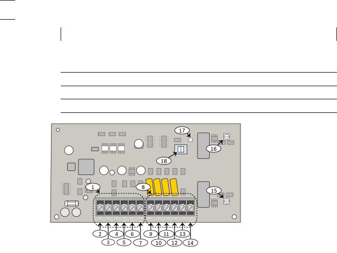
Figure 2.1: D185 reverse polarity signaling module
|
1 |
Input terminals |
10 |
Connects to telco line for sending |
|
|
|
|
supervisory signals |
|
|
|
|
|
|
2 |
Earth Ground |
11 |
Connects to telco line for sending |
|
|
|
|
alarm\trouble signals |
|
|
|
|
|
|
3 |
Common |
12 |
Connects to telco line for sending |
|
|
|
|
alarm\trouble signals |
|
|
|
|
|
|
4 |
Connects to control panel Aux or |
13 |
Not used |
|
|
external power supply (12 VDC or |
|
|
|
|
24 VDC) |
|
|
|
|
|
|
|
|
5 |
Connects to Trouble Relay on control |
14 |
Connects to end-of-line (EOL) |
|
|
panel |
|
supervisory relay (such as, D275, |
|
|
|
|
PAM 4) |
|
|
|
|
|
|
6 |
Connects to Supervisory Relay on |
15 |
Alarm signal adjuster |
|
|
control panel |
|
|
|
|
|
|
|
|
7 |
Connects to Alarm Relay on the control |
16 |
Supevisory signal adjuster |
|
|
panel |
|
|
|
|
|
|
|
|
8 |
Output terminals |
17 |
Alarm Test LED |
|
|
|
|
|
|
9 |
Connects to telco line for sending |
18 |
Alarm Test switch |
|
|
supervisory signals |
|
|
|
|
|
|
|
|
|
|
|
|
2013.05 | 03 | F.01U.034.781 |
Installation Instructions |
Bosch Security Systems, Inc. |

Reverse Polarity Signaling Module |
Notices | en |
5 |
|
|
|
3 Operation
Under normal conditions, the module sends a steady 10 mA of current to the alarm telco outputs and 14 mA of current to the supervisory output which connects to a monitoring station. In an alarm or supervisory condition, the module reverses the output current polarity and signals a trouble condition by interrupting the output voltage and current.
|
Input |
|
Output |
|
|
|
|
|
|
Alarm |
Supevisory |
Trouble |
Alarm |
Supervisory |
|
|
|
|
|
No Current |
No Current |
No Current |
Normal |
Normal |
|
|
|
|
|
No Current |
No Current |
Active High |
No Current |
Normal |
|
|
|
|
|
No Current |
Active High |
No Current |
No Current |
Reversed Polarity |
|
|
|
|
|
No Current |
Active High |
Active High |
No Current |
Reversed Polarity |
|
|
|
|
|
Active High |
No Current |
No Current |
Reversed Polarity |
Normal |
|
|
|
|
|
Active High |
Active High |
No Current |
Reversed Polarity |
Reversed Polarity |
|
|
|
|
|
Active High |
Active High |
Active High |
Reversed Polarity |
Reversed Polarity |
|
|
|
|
|
|
Table 3.1: Input and output states |
3.1 |
Alarm and trouble responses (alarm output telco lines) |
|
The module responds to an alarm input from the control panel by reversing the alarm telco |
|
output polarity. The module responds to a trouble input from the control panel by interrupting |
|
the current to the alarm telco outputs |
|
If the control panel sends an alarm during a trouble signal, the module overrides the trouble |
|
telco output and responds with an alarm telco output (reversed polarity). |
3.2 |
Supervisory response (supervisory output telco lines) |
|
The module responds to a supervisory signal input by reversing the polarity of the supervisory |
|
telco outputs. A second set of telco lines must be connected. |
3.3 |
Alarm test |
|
The Alarm Test Switch (Item 18 in Figure 1 on page 2) disables module output during testing |
|
that triggers a trouble output from the module during testing. Generally, this switch is off but |
|
during an Alarm Test, you must move the switch to the ON position. Turning on the Alarm Test |
|
Switch lights the Alarm Test LED (Item 17 in Figure 1). |
4 |
Installation |
Notice!
Install the module within 20 ft (6 m) of the control panel with a minimum of 22 AWG (0.34 mm2) wire. Ensure all wiring is in conduit.
Install the D185 in a system by:
Bosch Security Systems, Inc. |
Installation Instructions |
2013.05 | 03 | F.01U.034.781 |
Loading...