


CR 400
EMS 2
6 720 812 360-00.2O
User interface
CR 400 | CW 400 | CW 800
Owner’s manual
6 720 820 871 (2016/12)

2 | Contents
Contents
1 Key to symbols and safety instructions . . . . . . . . . . . . 3
1.1 Key to symbols . . . . . . . . . . . . . . . . . . . . . . . . . . . 3
1.2 General safety instructions . . . . . . . . . . . . . . . . . 3
2 Product information . . . . . . . . . . . . . . . . . . . . . . . . . . . . 3
2.1 Product data on energy consumption . . . . . . . . . 4
2.2 Range of functions . . . . . . . . . . . . . . . . . . . . . . . . 4
2.3 Function as controller . . . . . . . . . . . . . . . . . . . . . 4
2.4 Applicability of the technical documentation . . . 5
2.5 Declaration of Conformity . . . . . . . . . . . . . . . . . . 5
2.6 Operation after power failure . . . . . . . . . . . . . . . 5
3 Overview of control elements and symbols . . . . . . . . 5
4 Getting started . . . . . . . . . . . . . . . . . . . . . . . . . . . . . . . . 9
4.1 Selecting a heating circuit for the standard
display . . . . . . . . . . . . . . . . . . . . . . . . . . . . . . . . . .9
4.2 Setting the operating mode . . . . . . . . . . . . . . . . . 9
4.3 Changing the room temperature . . . . . . . . . . . . 10
4.4 Additional settings . . . . . . . . . . . . . . . . . . . . . . . 12
4.5 Activating emergency operation . . . . . . . . . . . . 14
4.6 Activating/deactivating heating/DHW . . . . . . . 15
4.7 Favourites functions . . . . . . . . . . . . . . . . . . . . . 16
6 Calling up information about the system . . . . . . . . . 36
7 Energy saving tips . . . . . . . . . . . . . . . . . . . . . . . . . . . . . 41
8 FAQ . . . . . . . . . . . . . . . . . . . . . . . . . . . . . . . . . . . . . . . . . 42
9 Eliminate fault . . . . . . . . . . . . . . . . . . . . . . . . . . . . . . . . 43
9.1 Eliminating "sensed" faults . . . . . . . . . . . . . . . . 43
9.2 Removing a displayed fault . . . . . . . . . . . . . . . . 44
10 Environment / disposal . . . . . . . . . . . . . . . . . . . . . . . . 46
Technical terms . . . . . . . . . . . . . . . . . . . . . . . . . . . . . . . 46
Index . . . . . . . . . . . . . . . . . . . . . . . . . . . . . . . . . . . . . . . . 48
5 Working with the main menu . . . . . . . . . . . . . . . . . . . 17
5.1 Main menu summary . . . . . . . . . . . . . . . . . . . . . 18
5.2 Heat source settings . . . . . . . . . . . . . . . . . . . . . 19
5.3 Adapting settings for heating system
automatic mode . . . . . . . . . . . . . . . . . . . . . . . . 19
5.3.1 Observe with constant heating circuit
(e.g. swimming pool or ventilation unit) . . . . . 21
5.3.2 Adapting Time program for automatic mode . . 21
5.3.3 Automatic adaptation of the time program . . . 25
5.3.4 Setting the summer/winter switchover
threshold . . . . . . . . . . . . . . . . . . . . . . . . . . . . . . 25
5.4 Changing the settings for DHW heating . . . . . . 26
5.4.1 Activating DHW heating immediately . . . . . . . . 26
5.4.2 Setting the DHW temperature . . . . . . . . . . . . . . 27
5.4.3 Setting the time program for DHW heating . . . 27
5.4.4 Settings for the DHW circulation . . . . . . . . . . . . 29
5.4.5 Thermal disinfection . . . . . . . . . . . . . . . . . . . . . 30
5.5 Setting up a holiday program . . . . . . . . . . . . . . 31
5.6 General settings . . . . . . . . . . . . . . . . . . . . . . . . . 35
5.7 Adapting the settings to hybrid systems . . . . . 36
6 720 820 871 (2016/12) CR 400 | CW 400 | CW 800
1 Key to symbols and safety instructions
Key to symbols and safety instructions | 3
All other use is not suitable. We cannot accept liability for
damages resulting from unauthorised use.
1.1 Key to symbols
Warnings
Warnings in this document are identified by a
warning triangle printed against a grey
background.
Keywords at the start of a warning indicate the
type and seriousness of the ensuing risk if
measures to prevent the risk are not taken.
The following keywords are defined and can be used in this
document:
• NOTICE indicates a situation that could result in damage to
property or equipment.
• CAUTION indicates a situation that could result in minor to
medium injury.
• WARNING indicates a situation that could result in severe
injury or death.
• DANGER indicates a situation that will result in severe
injury or death.
Important information
Inspection and maintenance
Regular inspection and maintenance are prerequisites for safe
and energy efficient operation of the heating system.
We recommend you enter into a contract for the annual
inspection and responsive maintenance with an approved
contractor.
▶ Have work carried out only by an approved contractor.
▶ If any faults are discovered, have them remedied
immediately.
Damage caused by frost
If the system is not in operation it can freeze:
▶ Follow the instructions to ensure protection from freezing.
▶ Always keep the system switched on for additional
functions, such as heating hot water or protection from
blocking.
▶ Rectify operating faults immediately.
Risk of scalding at the hot water draw-off points
▶ If hot water temperatures above 60 °C are set or if thermal
disinfection is activated, a mixer must be installed. If in
doubt, ask your contractor.
This symbol indicates important information
where there is no risk to people or property.
Additional symbols
Symbol Explanation
▶ Step in an action sequence
Æ Cross-reference to another part of the document
• List entry
– List entry (second level)
Table 1
1.2 General safety instructions
These instructions are intended for the user of the heating
system
▶ Read the instructions (for heat source, modules etc.)
before use and keep them handy.
▶ Pay attention to the safety and warning instructions.
Intended use
▶ The product should only be used to control heating systems
in one-family houses.
2 Product information
The user interfaces CR 400, CW 400 and CW 800 are
collectively referred to as C 400/C 800.
The C 400 user interface makes it easy to operate your C 800
heating system. Turn the selector to set the required room
temperature in your home. The thermostatic valves only need
to be adjusted if an individual room is too cold or too hot.
Automatic mode with the adjustable time program ensures
energy-efficient operation by reducing the room temperature
at certain times or by shutting down the entire heating system
(adjustable reduced temperature). This method of controlling
the heating optimises thermal comfort whilst minimising
energy consumption.
DHW heating can be adjusted conveniently and controlled
efficiently.
6 720 820 871 (2016/12)CR 400 | CW 400 | CW 800
4 | Product information
2.1 Product data on energy consumption
The specified product data correspond to the requirements of
the EU Regulation No. 811/2013 which supplements ErP
Directive 2010/30/EU. The class of the temperature controller
is required to calculate the central heating energy efficiency of
an integrated system and is for this reason incorporated into
the system data sheet.
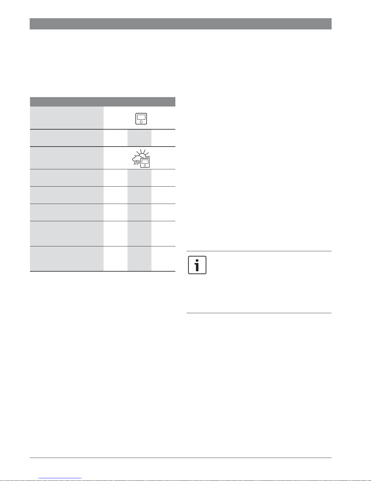
Function of the C 400/C 800 Class1)[%]
1),2)
CR 400
Room temperature-
V 3.0 z
dependent, modulating
CR 400/CW 400/CW 800 &
outside temperature sensor
Weather-compensated,
II menu
2.0
modulating
Weather-compensated, on/
III 1.5
off
Room temperature-
V 3.0
dependent, modulating
Weather-compensated with
VI
4.0 z
influence of room
temperature, modulating
Weather-compensated with
VII 3.5
influence of room
temperature, on/off
Table 2 Product data with regard to energy efficiency of
C 400/C 800
z Delivery condition
Adjustable
1) Classification of the user interface according to EU
Regulation 811/2013 for the identification of system
packages
2) Contribution to seasonal energy efficiency for central
heating in %
2.2 Range of functions
These instructions describe the maximum functional scope of
the equipment. Your attention is drawn to the importance of
the system structure in the relevant places. The setting ranges
and basic settings are determined by the local system
conditions and may deviate from the information provided in
these instructions. Depending on the software version of the
user interface, the texts shown in the display may differ from
the texts in these instructions.
The functional scope and thus the menu structure of the user
interface are determined by the structure of the system:
• Settings for a variety of heating circuits are only available if
two or more heating circuits are installed.
• If a CR100 user interface is assigned as a remote control for
a heating circuit, certain settings in that heating circuit can
only be made via the remote control (Æ CR100 operating
instructions).
• Settings for a variety of DHW systems will only be available
if two DHW systems are installed (e.g. in an apartment
building, where the DHW requirements of the residents can
vary greatly).
• Information about special system parts (e.g. solar system)
are only displayed if corresponding system parts are
installed.
• Certain menu items (e.g. heat source settings) are only
available for certain types of heat source or if no cascade
module (e.g. MC400) is installed.
Consult your contractor if you have further questions.
2.3 Function as controller
The C 400 user interface can control up to 4 heating circuits
and the C 800 up to 8 heating circuits. In each heating circuit of
the system, the heating controls operate in one of main control
modes. Depending on your requirements, your contractor will
select and set up one of these modes.
Rule of thumb for room temperaturedependent control and for weathercompensated control with influence of room
temperature:
the thermostatic valves in the reference room
(the room in which the user interface or a
remote control is installed) must be fully open!
The main control modes are:
• Room temperature-dependent (CR 400/CW 400/
CW 800):
– The room temperature is controlled based on the
measured room temperature
– The user interface sets the heat output required from
the heat source or the flow temperature, technical
terms Æ page 46.
• Weather-compensated (CW 400/CW 800):
– The room temperature is controlled based on the
outside temperature
– The user interface sets the flow temperature in
accordance with a simplified or optimised heating
curve.
6 720 820 871 (2016/12) CR 400 | CW 400 | CW 800
Overview of control elements and symbols | 5
• Weather-compensated with influence of room
temperature (CW 400/CW 800 with remote control):
– The room temperature is controlled based on the
outside temperature and the measured room
temperature
– The user interface sets the flow temperature in
accordance with a simplified or optimised heating
curve.
• Constant: Control with constant temperature
independently of outside or room temperature, e.g. for
swimming pool or ventilation unit. Flow temperature can be
set in the service menu only by a contractor.
2.4 Applicability of the technical documentation
Information in the technical documentation about heat
sources, heating controllers or the 2-wire BUS apply also to the
present user interface.
3 Overview of control elements and symbols
2.5 Declaration of Conformity
The design and operation of this product comply
with European Directives and the supplementary
national requirements. Its conformity is
demonstrated by the CE marking.
You can ask for a copy of the declaration of conformity for this
product. For this see the contact address on the back cover of
these instructions.
2.6 Operation after power failure
In the event of a power failure, or periods with disconnected
heat source, no settings are lost. The control unit starts again
when the power returns. It may be necessary to redo the
settings for the time and date. No other settings are necessary.
3
2
1
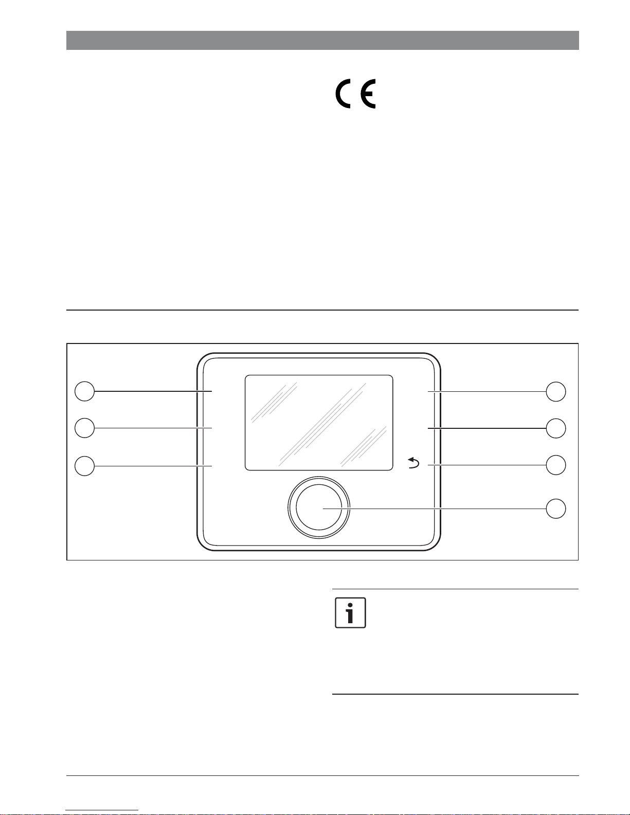
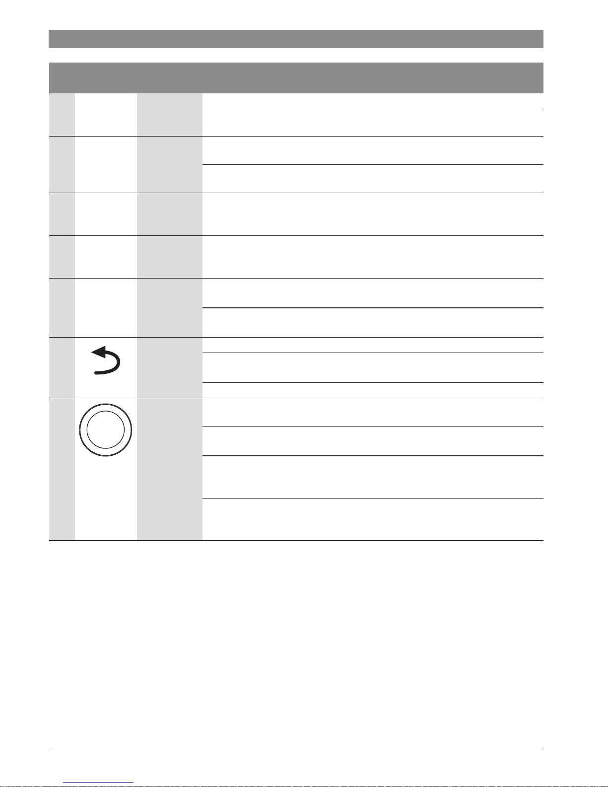
Fig. 1 Control elements
[1] fav key
[2] man key
[3] auto key
[4] menu key
[5] Info key
[6] Back key
[7] Selector
auto
man
fav
menu
info
4
5
6
7
6 720 812 360-01.2O
If the backlighting of the display is off, the
operating step is executed and the
backlighting is turned on by actuating a control
element. Pressing the selector for the first time
only activates the backlighting. If no control
element is actuated, the backlighting turns off
automatically.
6 720 820 871 (2016/12)CR 400 | CW 400 | CW 800
6 | Overview of control elements and symbols
Æ Fig. 1, page 5
Item Element Designation Explanation
1 fav key ▶ Press to call up the favourites functions for heating circuit 1.
fav
2 man key ▶ Press to activate the manual operating mode for permanent room temperature set
man
3 auto key ▶ Press to activate the automatic operating mode with the time program
auto
4 menu key ▶ Press to open the main menu (Æ Chapter 5, page 17).
▶ Hold down to individually adjust the favourites menu (Æ Chapter 4.7, page 16).
point (continuous operation without time program, Æ page 9).
▶ Hold down to activate the input field for the duration of manual operation (maximum
approx. 48 hours).
(Æ Chapter 4.2, page 9).
menu
5 Info key If a menu is open:
info
6 Back key ▶ Press to return to the higher menu level or discard a changed value.
7 Selector ▶ Turn to change a setting value (e.g. temperature) or select from among the menus or
Table 3 Control elements
▶ Press to call up more information about the current selection.
If the standard display is active:
▶ Press to open the info menu (Æ Chapter 6, page 36).
If the need for a service or a fault is displayed:
▶ Press to switch between standard display and fault display.
▶ Hold to switch from a menu to the standard display.
menu items.
If the backlighting is turned off:
▶ Press to turn on the backlighting.
If the backlighting is turned on:
▶ Press to open a selected menu or menu item, confirm a set value (e. g. temperature)
or a message or to close a pop-up window.
If the standard display is active:
▶ Press to activate the input field for selecting the heating circuit in the standard
display (systems with at least two heating circuits only, Æ Chapter 4.1, page 9).
6 720 820 871 (2016/12) CR 400 | CW 400 | CW 800

2
1
9
Overview of control elements and symbols | 7
3
4
5
6
8
Fig. 2 Example for a standard display of a system with more than one heating circuit
[1] Value display
[2] Information line
[3] Outside temperature
[4] Text information
[5] Information graphic
[6] Time program
[7] Time marker (current time)
[8] Operating mode
[9] User interface status
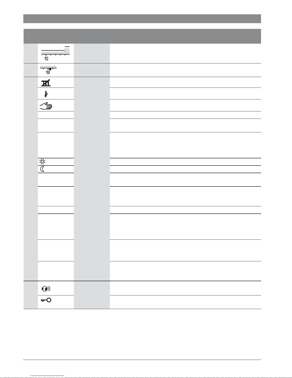
Æ Fig. 2, page 7
Item Symbol Designation Explanation
1 Value display Display of current temperature:
• Room temperature for wall-mounted installation
• Heat source temperature for installation in heat source.
2 – Information line Display of time of day, day of the week and date.
3 Additional
temperature
display
Display of an additional temperature: outside temperature, temperature of the
solar collector or a DHW system (for further information Æ page 35).
7
4 – Text information E.g. the designation of the temperature currently displayed (Æ Fig. 2, [1]); a
5 Information
graphic
B Heat source is blocked (e.g. by an alternative heat source).
Table 4 Symbols on the standard display
designation for the room temperature is not displayed. If a fault is present,
corresponding information will be displayed here until the fault has been
rectified.
Solar pump is in operation
DHW heating active.
DHW heating is switched off.
Burner is on (flame).
6 720 820 871 (2016/12)CR 400 | CW 400 | CW 800
8 | Overview of control elements and symbols
Æ Fig. 2, page 7
Item Symbol Designation Explanation
6 Time program Graphical display of the active time program for the heating circuit displayed. The
height of the bars represents roughly the desired room temperature in the
different time slots.
7 Time marker The time marker indicates the current time of day in the time program in
15 minute increments (= division of time scale).
8 Operating mode Heating is completely off (all heating circuits).
Chimney sweep mode is active.
Emergency operation is active.
E External heat requirement
auto System with one heating circuit in automatic mode (heating controlled by time
program)
HC2auto The displayed heating circuit operates in automatic mode. The standard display
refers only to the displayed heating circuit. Pressing the man key, the auto key
and changing the required room temperature in the standard display only affects
the heating circuit displayed.
Heating mode active in automatic mode in the displayed heating circuit
Setback mode active in automatic mode in the displayed heating circuit
Summer (off) System with one heating circuit in summer mode (heating off, DHW heating
active, Æ Chapter 5.3.4, page 25)
HC2Summer
(off)
The displayed heating circuit operates in summer mode (heating off, DHW
heating active). The standard display refers only to the displayed heating circuit
(Æ Chapter 5.3.4, page 25).
manual System with one heating circuit in manual operation
HC2manual The displayed heating circuit operates in manual operation. The standard display
refers only to the displayed heating circuit. Pressing the man key, the auto key
and changing the required room temperature in the standard display only affects
the heating circuit displayed.
Holiday until
10/6/2015
Holiday program active in system with one heating circuit
(Æ Chapter 5.5, page 31).
HC2Holiday until
10/6/2015
9 User interface
status
Table 4 Symbols on the standard display
6 720 820 871 (2016/12) CR 400 | CW 400 | CW 800
The holiday program is active in the displayed heating circuit and possibly for
DHW systems (Æ Chapter 5.5, page 31). The standard display refers only to the
displayed heating circuit.
A communication module is available in the system and a connection to the Bosch
server is active.
The key lock is active (hold down the auto key and the selector to activate or
deactivate the key lock).
4 Getting started
An overview of the structure of the main menu and the position
of the individual menu items can be found on page 17.
Each of the following descriptions takes the standard display as
its starting point (Æ page 2, Fig. 7 at left).
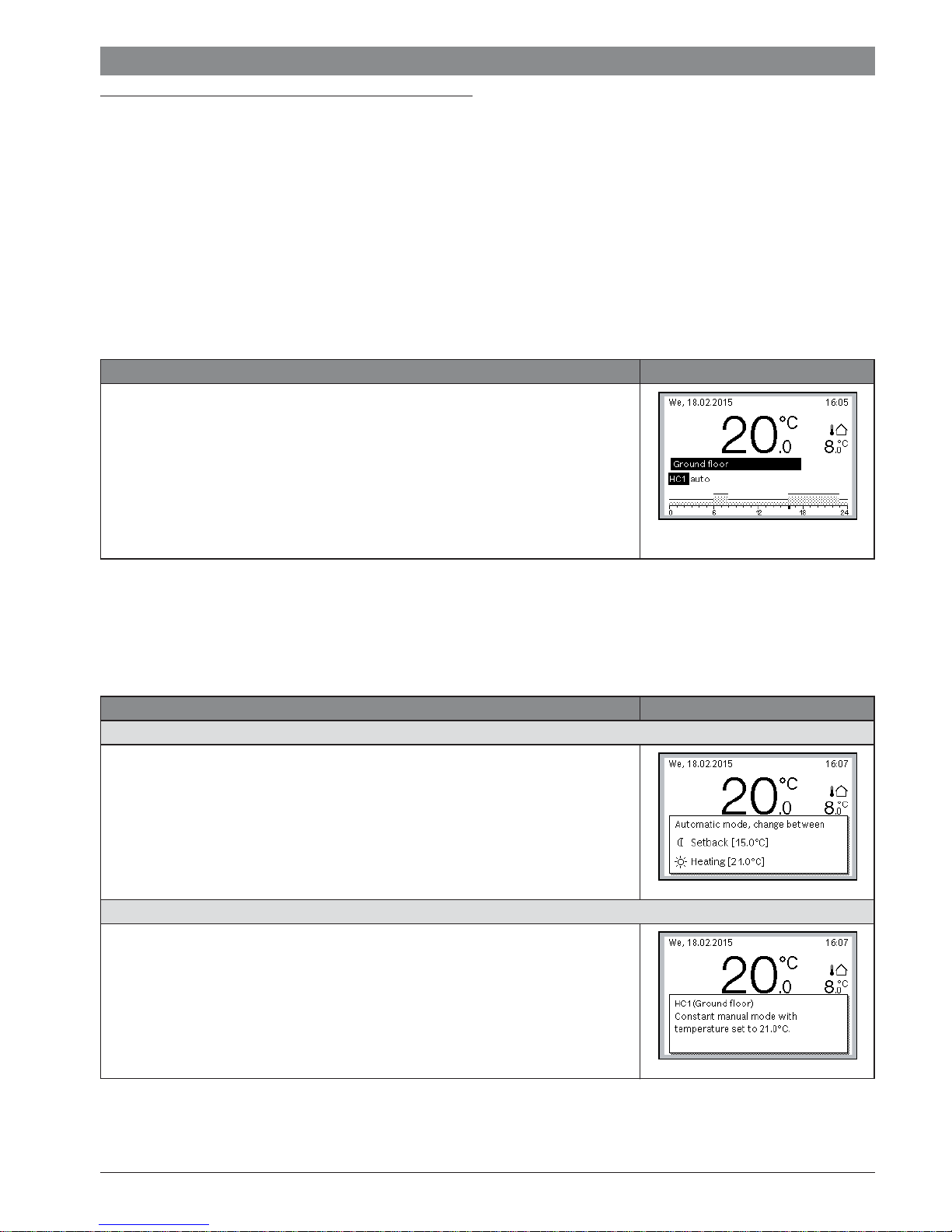
4.1 Selecting a heating circuit for the standard display
The standard display only ever shows data for a single heating
circuit. If two or more heating circuits are installed, a setting
can be made to determine which heating circuit the data in the
standard display relates to.
Operation Outcome
▶ If the backlighting is turned on, press the selector.
The number and operating mode of the heating circuit that is currently selected are
shown in the lower part of the display.
▶ Turn the selector to select a heating circuit.
Only heating circuits that exist in the system are displayed for selection.
▶ Wait a few seconds or press the selector.
The standard display refers to the heating circuit selected.
Note: Your installer can set the heating circuits that are available in the standard display.
Table 5 Getting started – Heating circuit in the standard display
Getting started | 9
6 720 815 237-01.1O
4.2 Setting the operating mode
An explanation of the technical terms “operating mode”,
“automatic mode” and “manual operation” can be found on
page 46 and 47.
Operation Outcome
To activate automatic mode (taking the time program into account),
▶ Press the auto key.
All temperatures set in the currently valid time program for the heating system are
shown in a pop-up window in the lower part of the display. The currently valid
temperature flashes.
The user interface controls the room temperature according to the active time
program for the heating system.
To activate manual operation (without taking the time program into account)
▶ Press the man key.
The required room temperature is shown in a pop-up window in the lower part of the
display.
The user interface regulates the room temperature permanently to the required room
temperature.
Note: If the control type constant is set for a heating circuit (e.g. swimming pool or
ventilation unit), there is no manual operation in this heating circuit.
6 720 815 237-02.1O
6 720 815 237-03.1O
Table 6 Getting started – Activating operating modes
6 720 820 871 (2016/12)CR 400 | CW 400 | CW 800
10 | Getting started
4.3 Changing the room temperature
If the control type constant is set for a heating
circuit (e.g. swimming pool or ventilation unit),
the temperature for this heating circuit can be
set only by a contractor. In this case, auto and
man keys do not have any function.
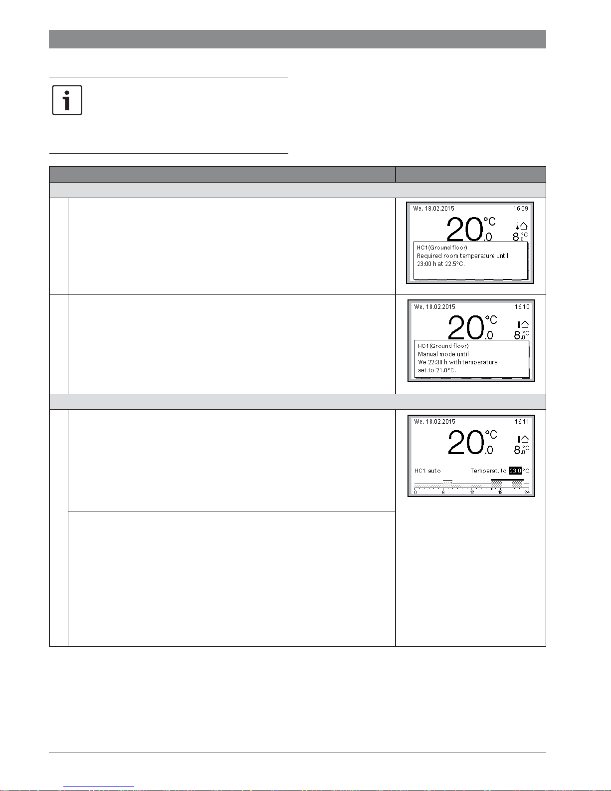
Operation Outcome
To check the current required room temperature
▶ Press the auto key.
The room temperature required currently (active operating mode) and the next
switching time are shown in a pop-up window in the lower part of the display.
Automatic mode
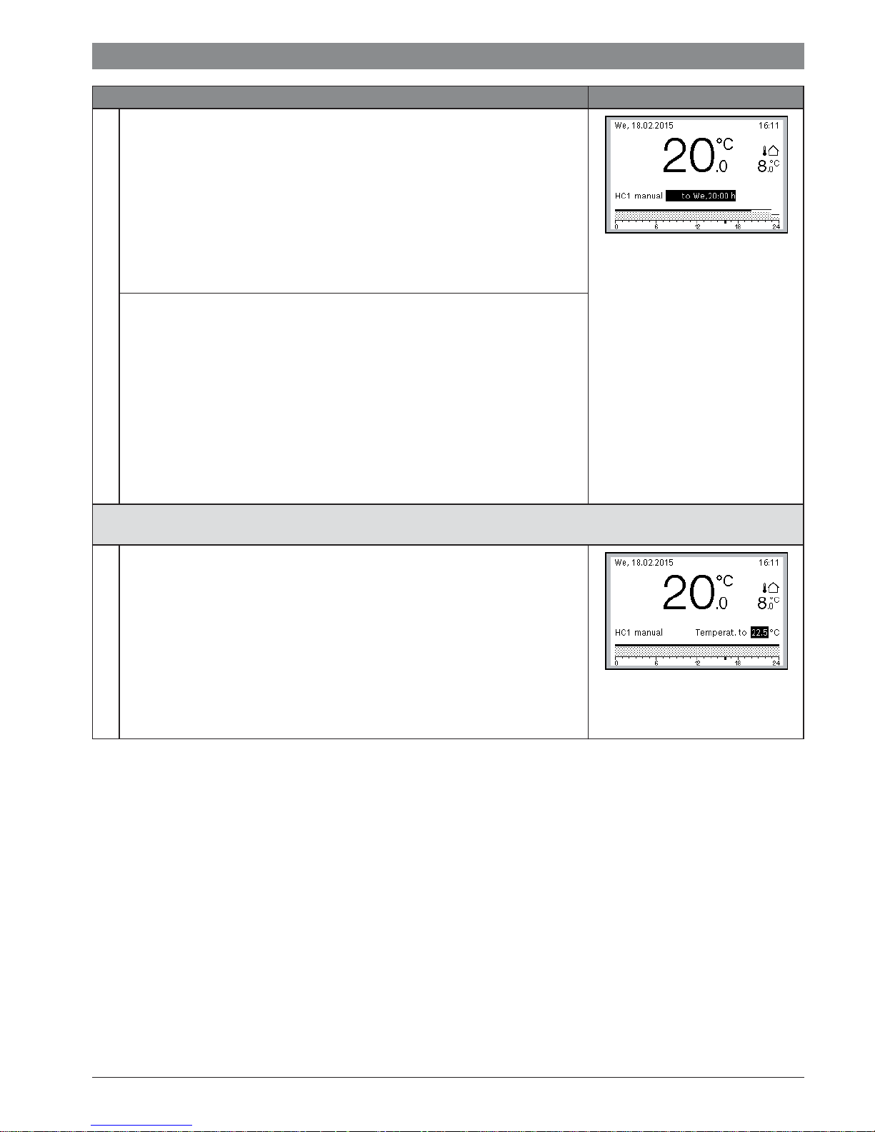
▶ Press the man key.
The required room temperature is shown in a pop-up window in the lower part of
the display.
If manual operation with restricted duration is active, the required room
temperature and the duration of manual operation are displayed.
Manual operation
If it is too cold or too warm for you today: Change the room temperature temporarily
Changing the room temperature until the next switching time
▶ Turn the selector to set the required room temperature.
The corresponding time slot is displayed in bold in the time program bar chart.
▶ Wait a few seconds or press the selector.
The user interface operates with the modified setting. The change applies until
the next switching time in your heating system time program is reached. After
this, the time program settings are restored.
Undoing a temperature change
▶ Turn the selector until the corresponding time slot is no longer displayed in bold
in the time program bar chart and press the selector
-or-
▶ To activate manual operation and then automatic mode:
– Press the man key.
– Wait a few seconds or press the selector to close the pop-up window.
– Press the auto key.
The change is undone.
Automatic mode
Table 7 Getting started – Room temperature
6 720 815 237-04.1O
6 720 815 237-05.1O
6 720 815 237-06.1O
6 720 820 871 (2016/12) CR 400 | CW 400 | CW 800
Getting started | 11
Operation Outcome
Setting a constant room temperature for a limited period of time
▶ Press and hold down the man key until the input field for the duration of manual
operation is displayed.
▶ Turn the selector to set the required duration.
The maximum limited duration for manual operation is approx. 48 hours
(2 days).
▶ Press the selector.
6 720 815 237-07.1O
The user interface operates with the modified settings.
If manual operation ends at the set time, the active time program is restored.
Cancelling limited duration for constant room temperature
▶ Set the duration to more than 48 hours (Æ setting a constant room temperature
for a limited period of time).
-or-
▶ To activate automatic mode and then manual operation:
– Activate automatic mode (press auto key).
– Wait a few seconds or press the selector to close the pop-up window.
– Activate manual operation (press man key).
Manual operation is active permanently (constant room temperature for an
unrestricted period of time).
Manual operation
If you require a room temperature for a period of time which deviates from the temperatures set for automatic mode: activate
manual operation and set the required room temperature
▶ Press the man key.
Manual operation is activated. The room temperature that is currently valid is
shown in a pop-up window in the lower part of the display. The time program bar
chart is displayed in bold.
▶ Wait a few seconds or press the selector to close the pop-up window.
▶ Turn the selector to set the required room temperature.
▶ Wait a few seconds or press the selector.
6 720 815 237-08.1O
The room temperature that is currently valid is shown in a pop-up window in the
lower part of the display.
The user interface operates with the modified settings.
Manual operation
Table 7 Getting started – Room temperature
6 720 820 871 (2016/12)CR 400 | CW 400 | CW 800
12 | Getting started
4.4 Additional settings
Operation Outcome
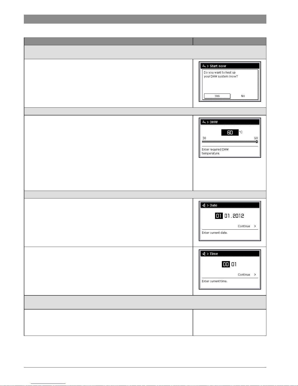
If you need hot water outside of the times set in the time program, activate the Heating once setting in the Start now menu (=
immediate hot water function).
▶ Press the menu key to open the main menu.
▶ Turn the selector to highlight DHW.
▶ Press the selector to open the DHW menu.
▶ Press the selector to open the Heating once menu.
▶ Press the selector twice to start the DHW heating.
The DHW heating is active immediately for the set duration. Depending on the
installed system, it may be necessary to select a DHW system (DHW system I or II).
If the DHW is too cold or too hot for you: change the DHW temperature
▶ Press the menu key to open the main menu.
▶ Turn the selector to highlight DHW.
▶ Press the selector to open the DHW menu.
▶ Turn the selector to highlight Temperature settings.
▶ Press the selector to open the Temperature settings menu.
▶ Turn the selector to highlight DHW or DHW reduced.
▶ Press the selector.
▶ Turn the selector to set the temperature.
▶ Press the selector.
The user interface operates with the modified settings. Depending on the installed
system, it may be necessary to select a DHW system (DHW system I or II).
Setting the date and time
If the user interface has been disconnected from the power supply for a prolonged
period, the display will prompt the user to enter the date and time before reverting back
to normal operation.
▶ Restore the power supply.
The user interface displays the setting for the date.
▶ Turn the selector to set the day, month and year.
Continue is highlighted in the display.
▶ Press the selector.
▶ Set the time in the same way as the date.
Continue is highlighted in the display.
▶ Press the selector.
The user interface operates with the modified settings. No other settings are required
to recommission the user interface.
To prevent the settings for the user interface from being modified inadvertently:
Activate or deactivate key block (child lock, Æ page 47)
▶ Press and hold down the auto key and the selector for a few seconds to activate or
deactivate the key block.
When the key block is enabled, the key symbol appears in the display
(Æ Fig. 2 [5], page 7).
Table 8 Getting started – More settings
6 720 815 237-09.1O
6 720 815 237-10.1O
6 720 815 237-11.1O
6 720 815 237-12.1O
6 720 820 871 (2016/12) CR 400 | CW 400 | CW 800

Operation Outcome
To change the language of the display texts: set language
▶ Press the menu key to open the main menu.
▶ Turn the selector to highlight Settings.
▶ Press the selector to open the Settings menu.
▶ Press the selector.
▶ Turn the selector to select a language.
▶ Press the selector.
The user interface operates with the modified settings.
If your day/night pattern changes (e.g. if you work shifts): adapt time program
In the Heating > Time program menu, the time program can be adapted to suit your
personal lifestyle habits or circumstances in just a few easy steps
(Æ Chapter 5.3.2, page 21).
Table 8 Getting started – More settings
Getting started | 13
6 720 815 237-13.1O
6 720 815 237-14.1O
6 720 820 871 (2016/12)CR 400 | CW 400 | CW 800
14 | Getting started
4.5 Activating emergency operation
It is possible to activate the emergency operation for certain
types of heat source by selecting the heat source menu item
from the main menu. In emergency operation the heat source
enters the heating mode until the burner has reached the set
Operation Outcome
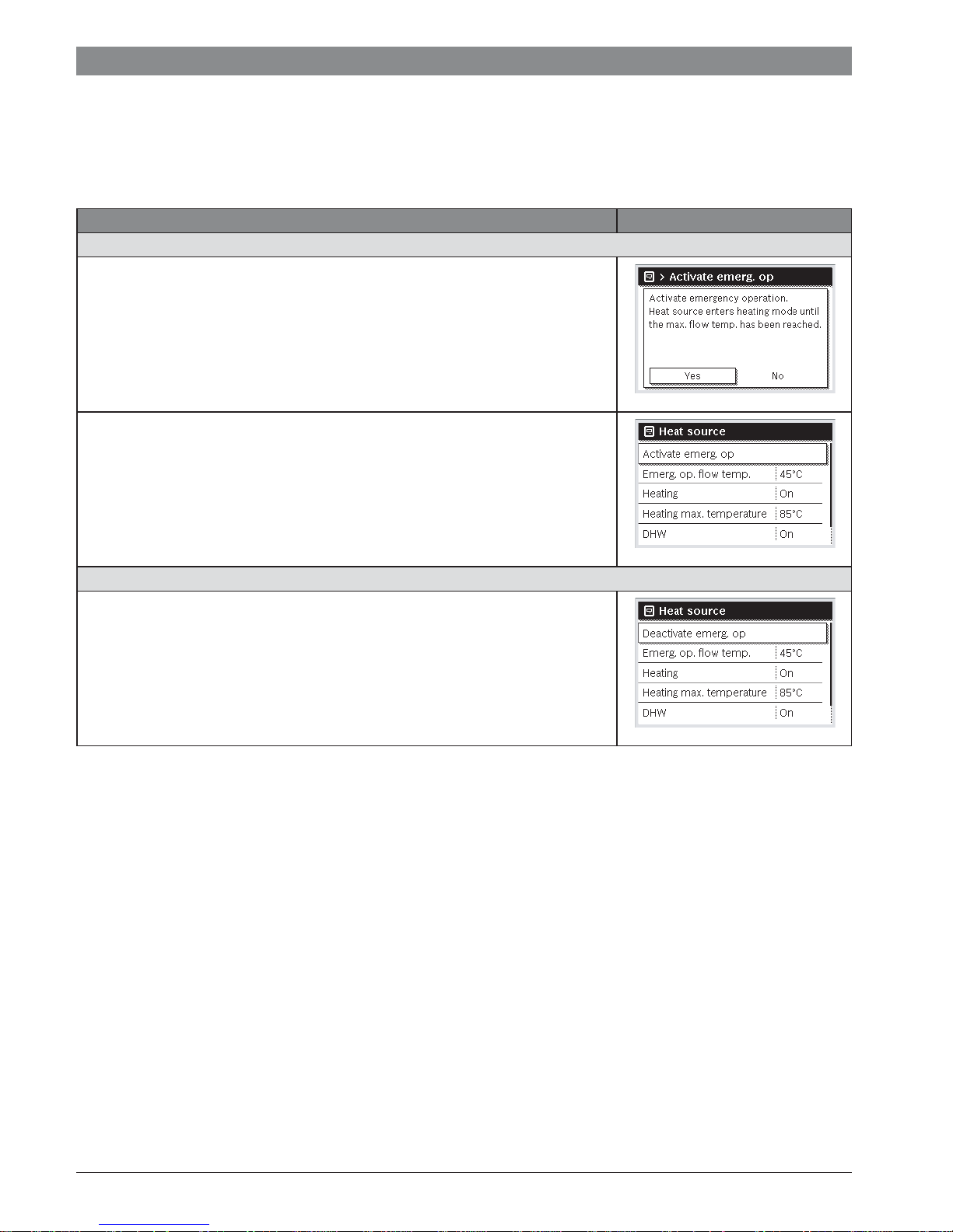
Activating emergency operation
▶ Press the menu key to open the main menu.
▶ Press the selector to open the Heat appliance menu.
▶ Press the selector to select Activate emergency operation.
A pop-up window is displayed which prompts you to activate the emergency
operation.
▶ If Yes is highlighted, press the selector to activate the emergency operation.
The display returns to the Heat appliance menu.
▶ Turn the selector to highlight Emerg. op. flow temp..
▶ Press the selector.
▶ Turn the selector to set the temperature.
▶ Press the selector.
The system operates with the modified settings in emergency operation.
Deactivate emergency operation
▶ Press the menu key to open the main menu.
▶ Press the selector to open the Heat appliance menu.
▶ Press the selector to select Deactivate emergency operation.
A pop-up window is displayed which prompts you to deactivate the emergency
operation.
▶ If Yes is highlighted, press the selector to deactivate the emergency operation.
The system reverts to normal operation.
flow temperature. A heat supply for heating and DHW is thus
guaranteed in the event of a fault until a contractor has repaired
the heating system.
6 720 815 820-94.1O
6 720 815 820-95.1O
6 720 815 820-96.1O
Table 9 Getting started – Emergency operation
6 720 820 871 (2016/12) CR 400 | CW 400 | CW 800
Getting started | 15
4.6 Activating/deactivating heating/DHW
It is possible to activate and deactivate the heating and the
DHW for certain types of heat source by selecting the heat
source menu item from the main menu. Thus, for example, the
system can be controlled manually before a short-term
absence of a few days without the need to set up a holiday
program. This function is only available if the system is
designed and configured accordingly (e.g. in systems without
cascade module). The activation/deactivation of the heating is
described in Tab. 15. DHW can be operated in the same way.
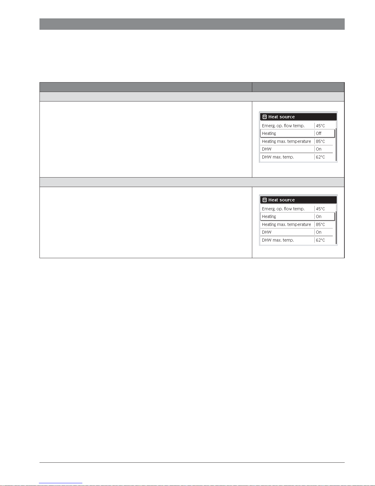
Operation Outcome
Deactivate the heating
▶ Press the menu key to open the main menu.
▶ Press the selector to open the Heat appliance menu.
▶ Turn the selector to highlight Heating.
▶ Press the selector to select Heating.
▶ Turn and press the selector to deactivate the heating (Off) or to cancel the selection
(On).
The changes are effective immediately.
▶ Press the Back key to close the menu.
Activate heating
▶ Press the menu key to open the main menu.
▶ Press the selector to open the Heat appliance menu.
▶ Turn the selector to highlight Heating.
▶ Press the selector to select Heating.
▶ Turn and press the selector to activate the heating (On) or to cancel the selection
(Off).
The changes are effective immediately.
▶ Press the Back key to close the menu.
6 720 815 820-62.1O
6 720 815 820-64.1O
Table 10 Getting started – Activating/deactivating heating/DHW
6 720 820 871 (2016/12)CR 400 | CW 400 | CW 800
16 | Getting started
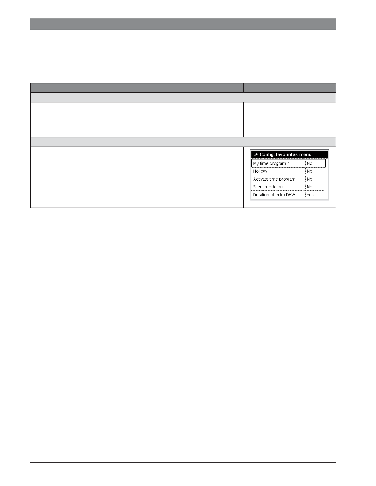
4.7 Favourites functions
Via the fav key you have direct access to often used functions
for heating circuit 1. The first pressing of the fav key opens the
menu for configuring the favourites menu. There you can add
your personal favourites and if necessary later adapt the
favourites menu to your requirements.
The function of the fav key is independent of the heating circuit
displayed in the standard display. Settings changed via the
favourites menu always apply only to heating circuit 1.
Operation Outcome
To access a favourites function: open the favourites menu
▶ Press the fav key to open the Favourites menu.
▶ Turn and press the selector to select a favourites function.
▶ Change the settings (operation is the same as when making a setting in the main
menu).
To adapt the list of favourites to meet your requirements: adapt the Favourites menu
▶ Press and hold down the fav key until the menu for configuring the Favourites menu is
displayed.
▶ Turn and press the selector to select a function (Yes) or to cancel your selection (No).
The changes are effective immediately.
▶ Press the Back key to close the menu.
Table 11 Getting started – Favourites functions
6 720 811 136-15.1O
6 720 820 871 (2016/12) CR 400 | CW 400 | CW 800
 Loading...