


D-TECT 100
Bedienungsanleitung
Operating instructions
Instructions d’emploi
Instrucciones de servicio
Manual de instruções
Istruzioni d’uso
Gebruiksaanwijzing
Betjeningsvejledning
Bruksanvisning
Brukerveiledningen
Käyttöohje
Οδηγία χειρισµού
Kullan∂m k∂lavuzu
Deutsch
English
Français
Español
Português
Italiano
Nederlands
Dansk
Svenska
Norsk
Suomi
Eλληvικά
Türkçe
wallSCANNER
D-TECT 100

A
B
C
14
2
11
1 609 203 D42
1 609 203 D43
1 609 203 D44
1

3
4
5
6
8
2
9
1
7
10
11
12
a
b
13
Deutsch–1
1 609 929 C66 • (02.03) T
Gefahrloses Arbeiten mit dem Gerät ist nur möglich, wenn Sie die Bedienungsanleitung und die Sicherheitshinweise vollständig lesen und die darin
enthaltenen Anweisungen strikt befolgen.
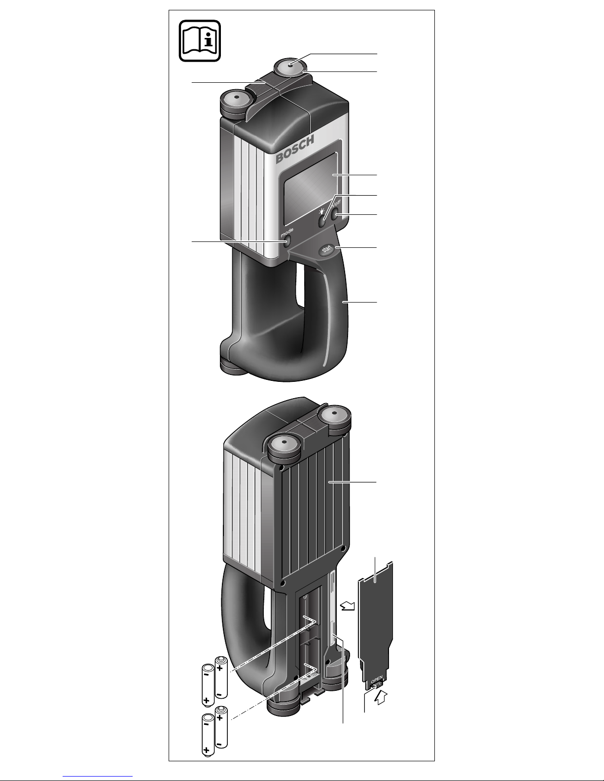
Die Nummerierung der Geräteelemente bezieht sich auf die Darstellung
des Gerätes auf der Ausklappseite.
1 Schraube
2 Rad
3 Display
4 Taste Displaybeleuchtung
5 Ein-Aus-Taste „on/off“
6 Taste Messen „start“
7 Handgriff
8 Taste „mode“
9 Ausrichthilfe
10 Sensorbereich
11 Batteriefachdeckel
12 Arretierung Batteriefach
13 Seriennummer
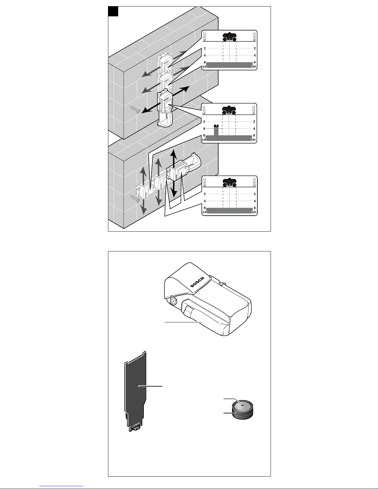
14 Schutztasche
* abhängig von Material und Größe der Objekte sowie Material und Zustand des
Untergrundes (siehe Funktionsweise)
** siehe Grafik:
Zu Ihrer Sicherheit
Geräteelemente
Gerätekennwerte
Universalortungsgerät Wallscanner D-tect 100
Bestellnummer 0 601 095 003
max. Messtiefe* [cm] 10
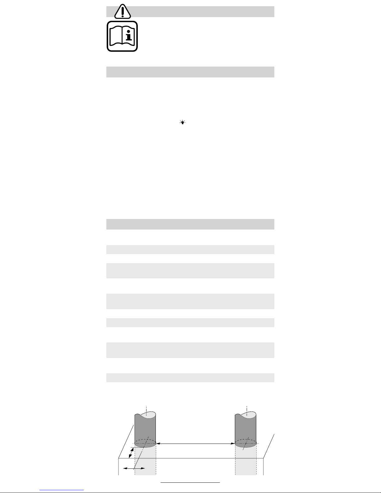
Messgenauigkeit zum
Objektmittelpunkt a** [mm] ±5
Genauigkeit der angezeigten
zulässigen Bohrtiefe b** [mm] ±5
Mindestabstand zweier
benachbarter Objekte c** [mm] 40
Betriebstemperatur [°C] –10 … +50
Lagertemperatur [°C] –20 … +70
Batterie
Akku
4 x 1,5 V LR6 (AA)
4 x 1,2 V KR6 (AA)
Betriebsdauer
(Alkali-Mangan-Batterien) ca. [h] 13
Schutzart (nach IEC 529) IP 54 (staub- und
spritzwassergeschützt)
Gewicht (mit Batterien) ca. [g] 800
a
b
c
Deutsch–2
1 609 929 C66 • (02.03) T
Auf dem Typenschild an der Gehäuseunterseite ist die Seriennummer
13 Ihres Gerätes zur eindeutigen Identifizierung angebracht.
Bitte die Bestellnummer Ihres Gerätes beachten, die Handelsbezeichnungen einzelner Geräte können variieren.
Das Gerät ist bestimmt zur Suche nach Objekten wie z.B. Metalle,
Holz, Kunststoffrohre, Leitungen und Kabel in Wänden, Decken und
Fußböden sowie zur Anzeige der zulässigen Bohrtiefe in Bezug auf die
gefundenen Objekte.
■ Gerät vor Nässe und direkter Sonneneinstrahlung schützen.
■ Um die Messergebnisse nicht zu beeinflussen, dürfen im Sensorbe-
reich 10 auf der Rückseite des Gerätes keine Aufkleber oder Schilder, insbesondere keine Schilder aus Metall, angebracht werden.
■ Wird das Gerät längere Zeit nicht benutzt, müssen die Batterien he-
rausgenommen werden (Gefahr von Korrosion).
■ Gerät in der Schutztasche 14 transportieren und lagern.
Ausschließlich Alkali-Mangan-Batterien oder Akkus verwenden.
Zum Öffnen des Batteriefachdeckels 11 Arretierung 12 in Pfeilrichtung
drücken (a) und anheben. Batteriefachdeckel abnehmen (b). Mitgelieferte Batterien einsetzen. (Siehe Darstellung auf der Ausklappseite.)
Beim Einsetzen der Batterien auf richtige Polung achten.
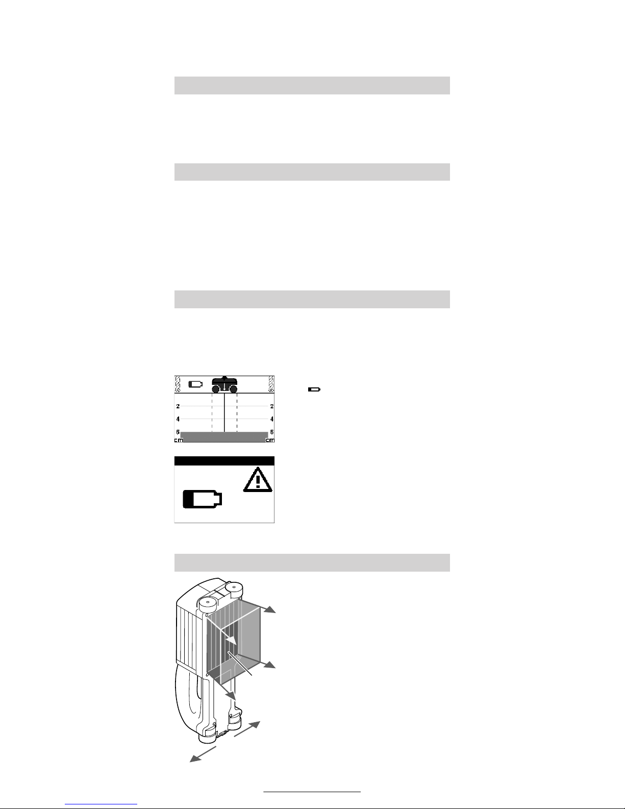
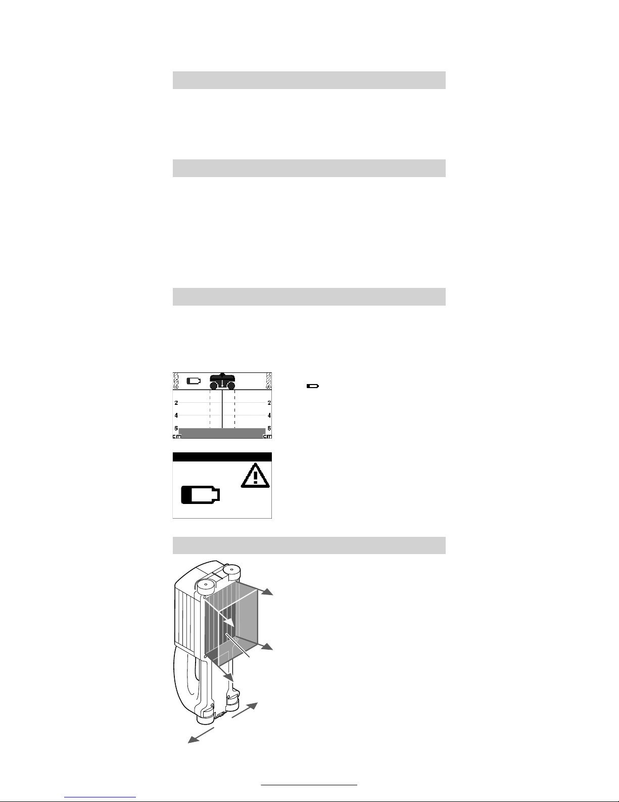
Bei Erscheinen des kleinen Batteriesymbols oben links im Display kann das
Gerät bei Verwendung von Alkali-Mangan-Batterien noch ca. 30 min betrieben
werden (bei Akkus kürzere Standzeit).
Erscheint im Display der nebenstehende
Hinweis, müssen die Batterien ausgewechselt werden. Messungen sind nicht
mehr möglich.
Batterien immer komplett ersetzen. Nur
Batterien eines Herstellers mit gleicher
Kapazität verwenden.
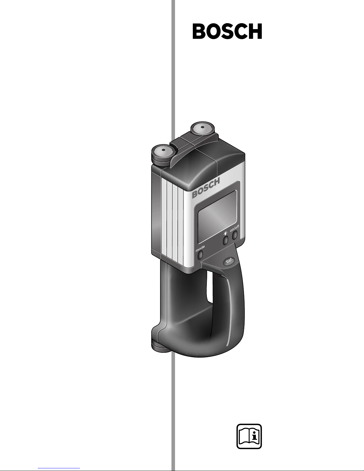
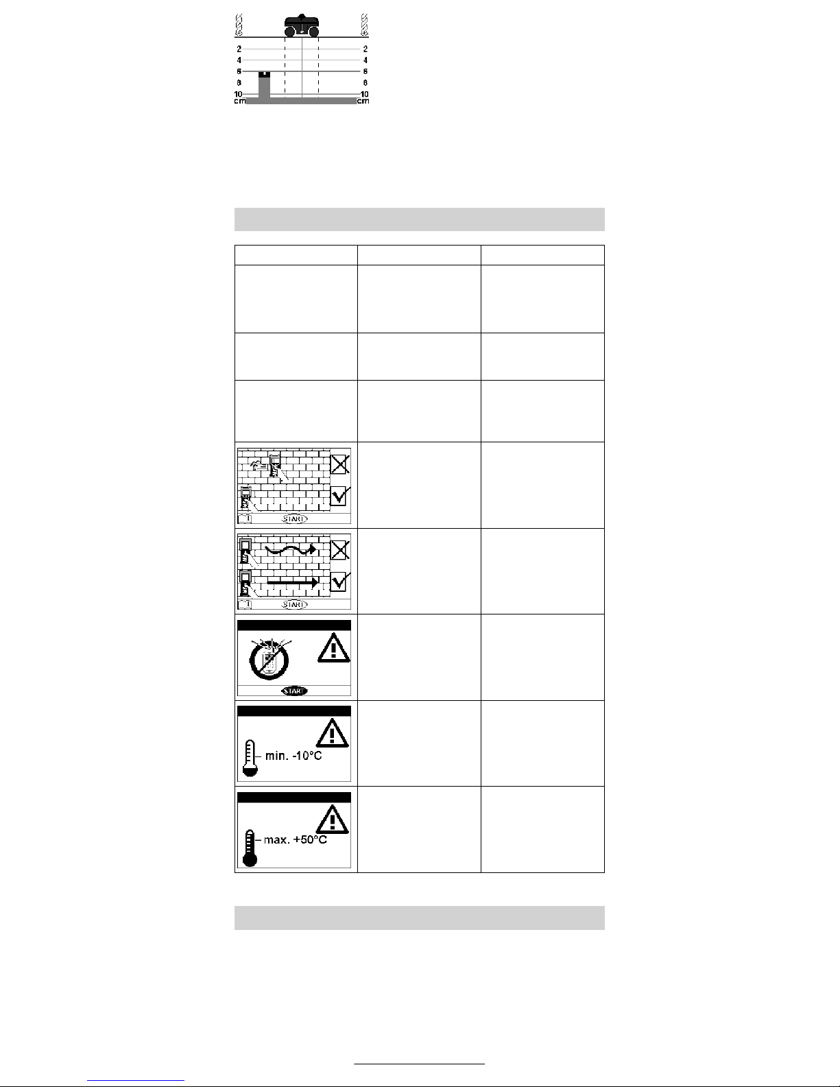
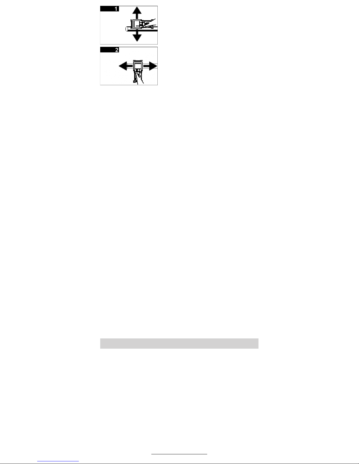
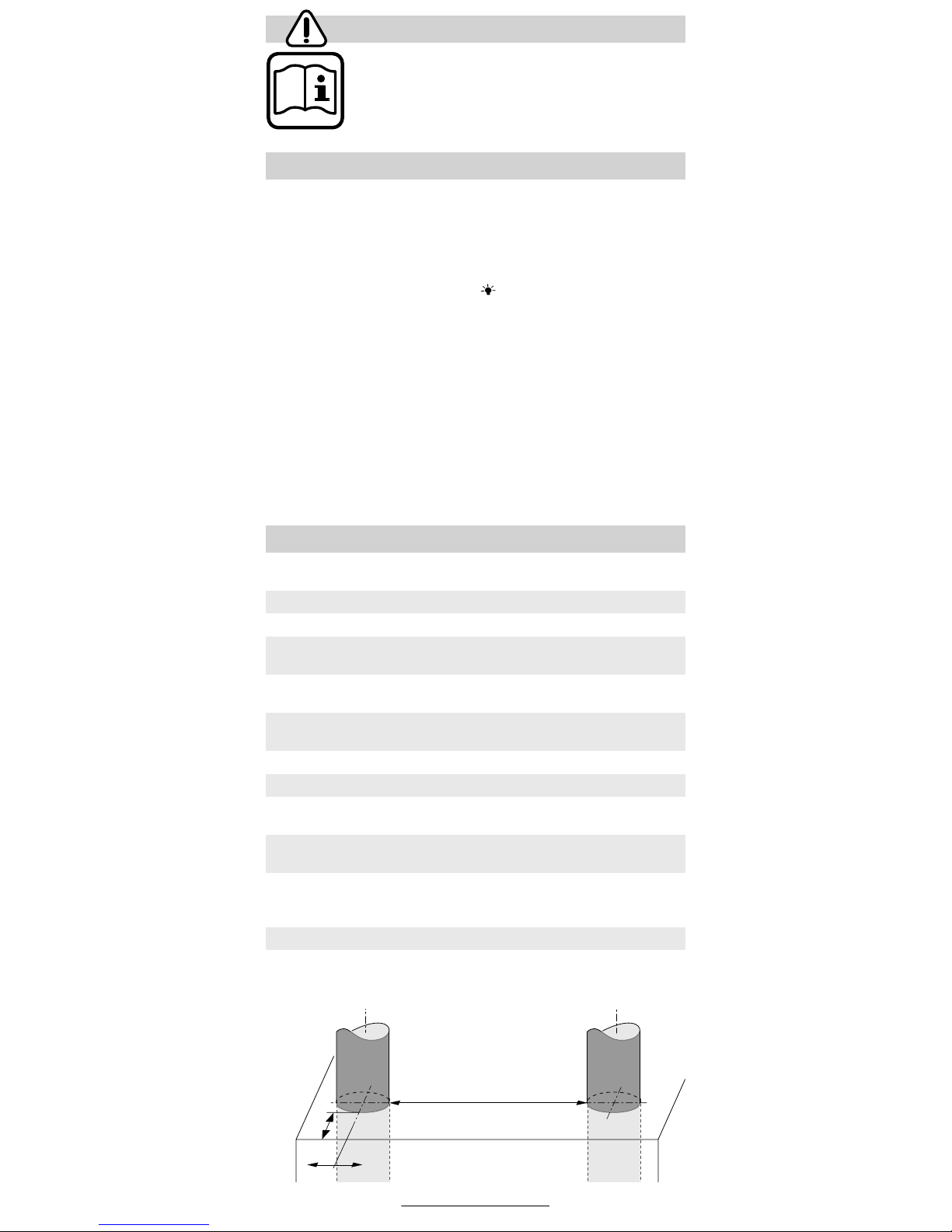
Mit dem Gerät wird der Untergrund des
Sensorbereiches 10 in Messrichtung A
bis zur maximalen Messtiefe überprüft.
Die Messung ist nur während der Bewegung des Gerätes in Fahrtrichtung B und
bei einer Mindestmessstrecke von 8 cm
möglich.
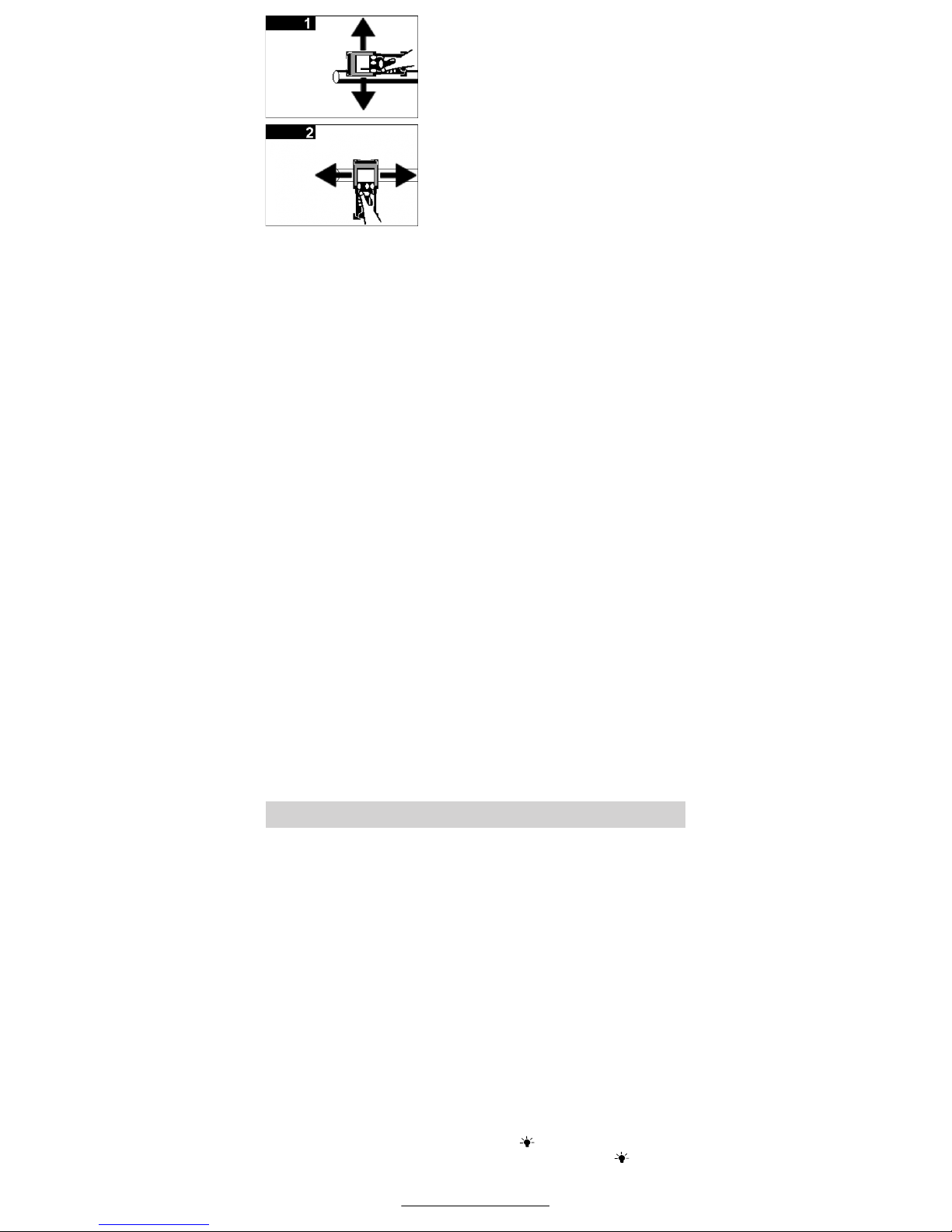
Das Gerät stets geradlinig mit leichtem Druck über die Wand bewegen,
so dass die Räder sicheren Wandkontakt haben. Erkannt werden Objekte, die sich vom Material der Wand
unterscheiden. Im Display wird jedoch die jeweils zulässige Bohrtiefe
angezeigt.
Optimale Ergebnisse werden erzielt,
wenn die Messstrecke mindestens 40 cm
beträgt und das Gerät über die gesamte
zu untersuchende Stelle bewegt wird.
Bestimmungsgemäßer Gebrauch
Geräteschutz
Batterien einsetzen/wechseln
Funktionsweise
A
B
B
10
Deutsch–3
1 609 929 C66 • (02.03) T
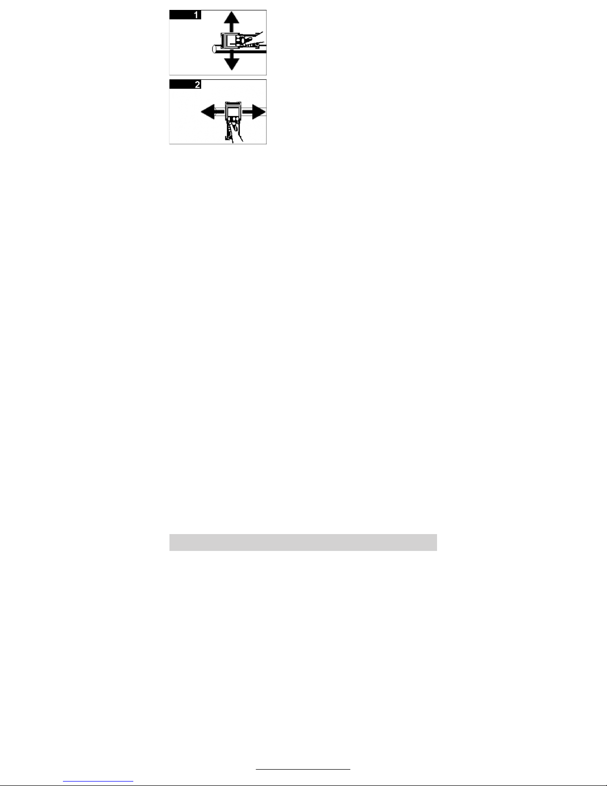
Zuverlässig gefunden werden nur Objekte, die quer zur Bewegungsrichtung des
Gerätes verlaufen.
Deshalb den zu untersuchenden Bereich immer kreuzweise abfahren.
Objekte, die deutlich größer als das Gerät
sind, können jedoch auch bei paralleler
Bewegungsrichtung angezeigt werden.
Die Anzeige des Gerätes wurde auf größtmögliche Sicherheit beim Bohren hin optimiert. Bis zur ermittelten max. Bohrtiefe
kann gebohrt werden.
Befinden sich mehrere Objekte übereinander in der Wand, wird im Display das Objekt angezeigt, welches der Oberfläche am nächsten liegt.
Feststellbare Objekte:
– Metalle jeglicher Art (z.B. Stahl, Kupfer, Aluminium)
– Kunststoffrohre (z.B. Wasserrohre, Leerrohre)
– Holz (z.B. Balken)
– Elektrische Leitungen (unabhängig, ob spannungsführend oder
nicht)
– Dreiphasige Drehstromleitungen (z.B. zum Herd)
– Kleinspannungsleitungen (z.B. Klingel, Telefon)
– Hohlräume
Messung möglich in:
– Beton/Stahlbeton
– Mauerstein (Ziegel, Porenbeton, Blähbeton, Bims)
– Leichtbauwänden
– sowie unter Oberflächen wie Putz, Fliesen, Tapeten, Parkett, Tep-
pich
Besondere Messfälle
Unter ungünstigen Umständen kann das Gerät bestimmte Objekte
prinzipbedingt nicht sicher erkennen, z. B.:
– Leere Kunststoffrohre in Hohlräumen werden nicht erkannt.
– Metalloberflächen und feuchte Oberflächen mit hohem Wasserge-
halt können nicht durchdrungen werden. Sie werden selbst als Ob-
jekte angezeigt.
– Feuchte Bereiche in einer Wand können unter Umständen (z.B. bei
hohem Wassergehalt) als Objekte angezeigt werden.
– Bei mehrschichtigem Aufbau von Wänden, z.B. durch Wandver-
kleidungen, wird möglicherweise nur die erste Grenzschicht (z.B.
Hohlraum hinter der Wandverkleidung) angezeigt.
– Hohlräume in einer Wand werden als Objekte angezeigt.
– Größere zylindrische Objekte (z.B. Kunststoff- oder Wasserrohre)
können in der Anzeige schmaler erscheinen als sie tatsächlich sind.
Vor der Inbetriebnahme sicherstellen, dass der Sensorbereich
10 nicht feucht ist. Gegebenenfalls Gerät mit einem Tuch trockenreiben.
Ein-Aus-Schalten
Einschalten:
Ein-Aus-Taste „on/off“ 5 oder Taste „start“ 6 drücken. Der beleuchtete Startbildschirm erscheint.
Vor Beginn der Messung (siehe Messvorgang) kann durch Drücken der
Taste „mode“ 8 eine Erläuterung zur Funktionsweise des Gerätes im
Display 3 abgerufen werden.
Ausschalten:
Ein-Aus-Taste „on/off“ 5 drücken.
Nach ca. 5 min ohne Durchführung einer Messung schaltet das Gerät
zur Schonung der Batterien automatisch ab.
Displaybeleuchtung
Bei Dunkelheit Taste Displaybeleuchtung 4 drücken. Das Display
wird beleuchtet. Zum Ausschalten der Beleuchtung Taste 4 erneut
drücken.
Inbetriebnahme
Deutsch–4
1 609 929 C66 • (02.03) T
Das Gerät stellt die Wand nicht in der Durchsicht, sondern im
Querschnitt dar.
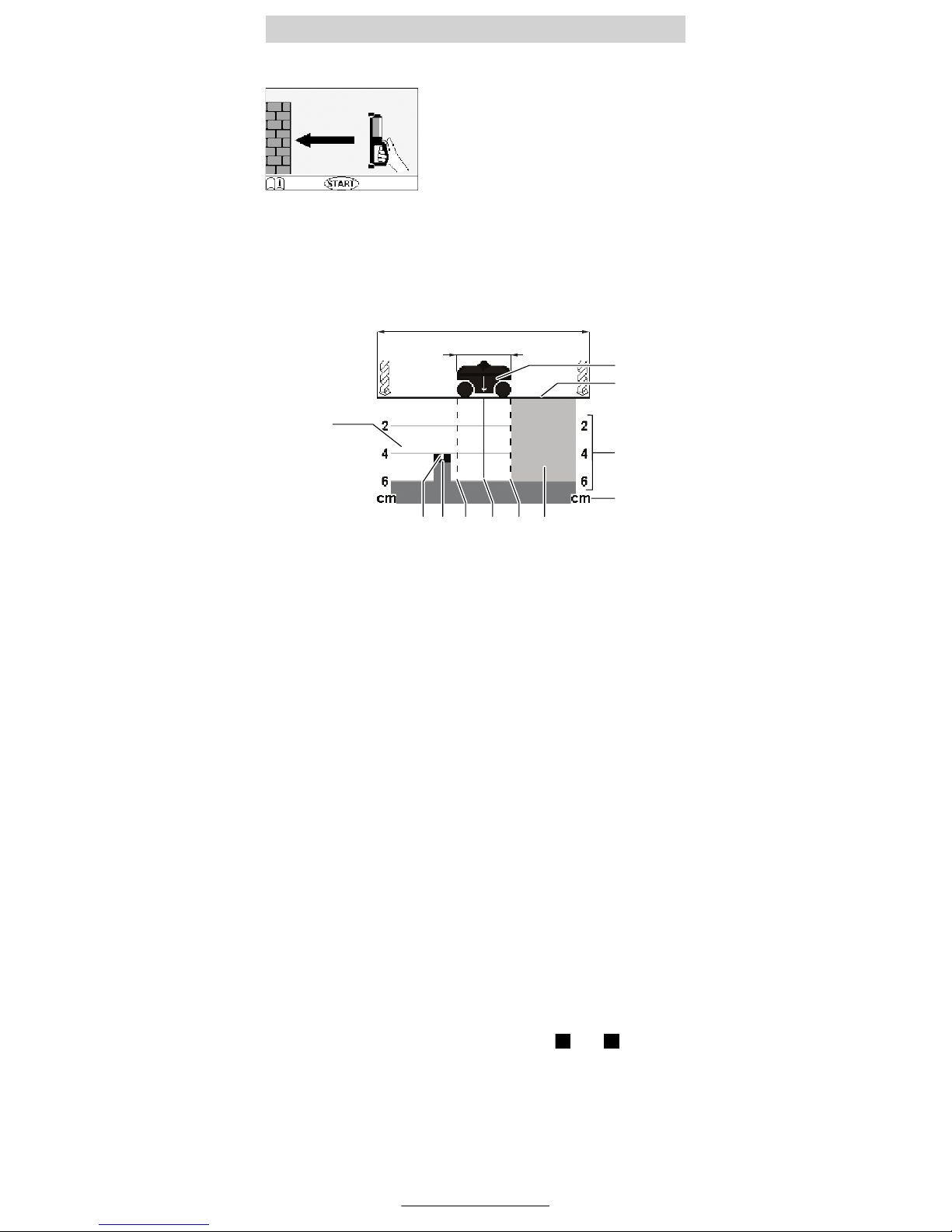
Wurde das Gerät nicht auf der Wand eingeschaltet, erscheint im Display eine Aufforderung, das Gerät zum Messen auf die
Wand aufzusetzen.
Gerät in Fahrtrichtung (siehe Funktionsweise) über die Wand bewegen.
Die Messergebnisse werden sofort im Display 3 angezeigt. Zur Sicherung korrekter Messergebnisse muss mindestens eine Strecke von
8 cm überfahren werden.
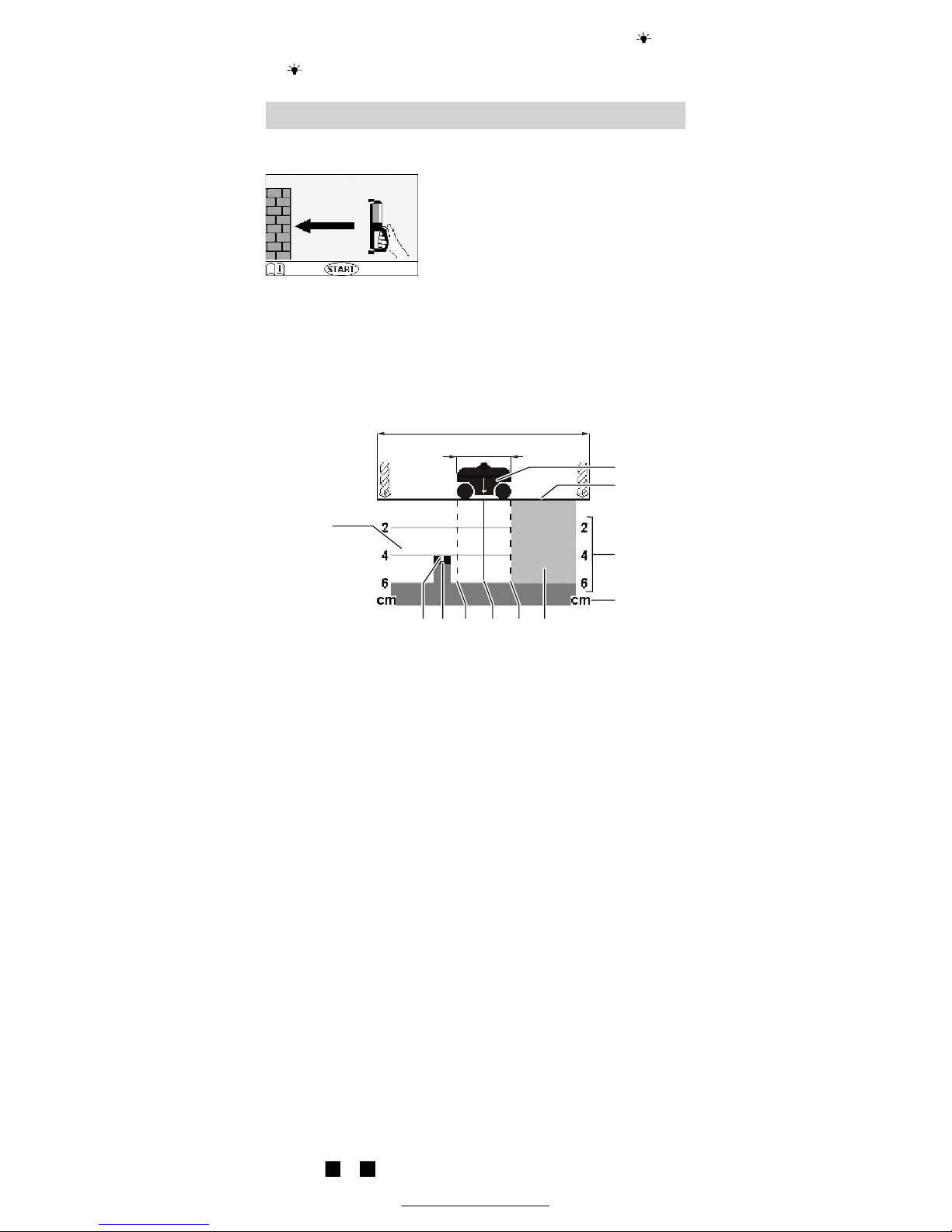
Während der Messung erscheinen folgende Anzeigeelemente:
Anzeigeelemente
a Querschnitt des Gerätes
b Wandoberfläche
c Tiefenskala für zulässige Bohrtiefe
d Maßeinheit der Tiefenskala
e grau: noch nicht untersuchter Bereich
f Außenkanten des Gerätes
g Mittellinie des Gerätes, Lage entspricht Ausrichthilfe 9 am Gerät
h Mittellinie des Objektes, das in der Wand gefunden wurde
i schwarz: in der Wand gefundenes Objekt
k weiß: bereits untersuchter Bereich
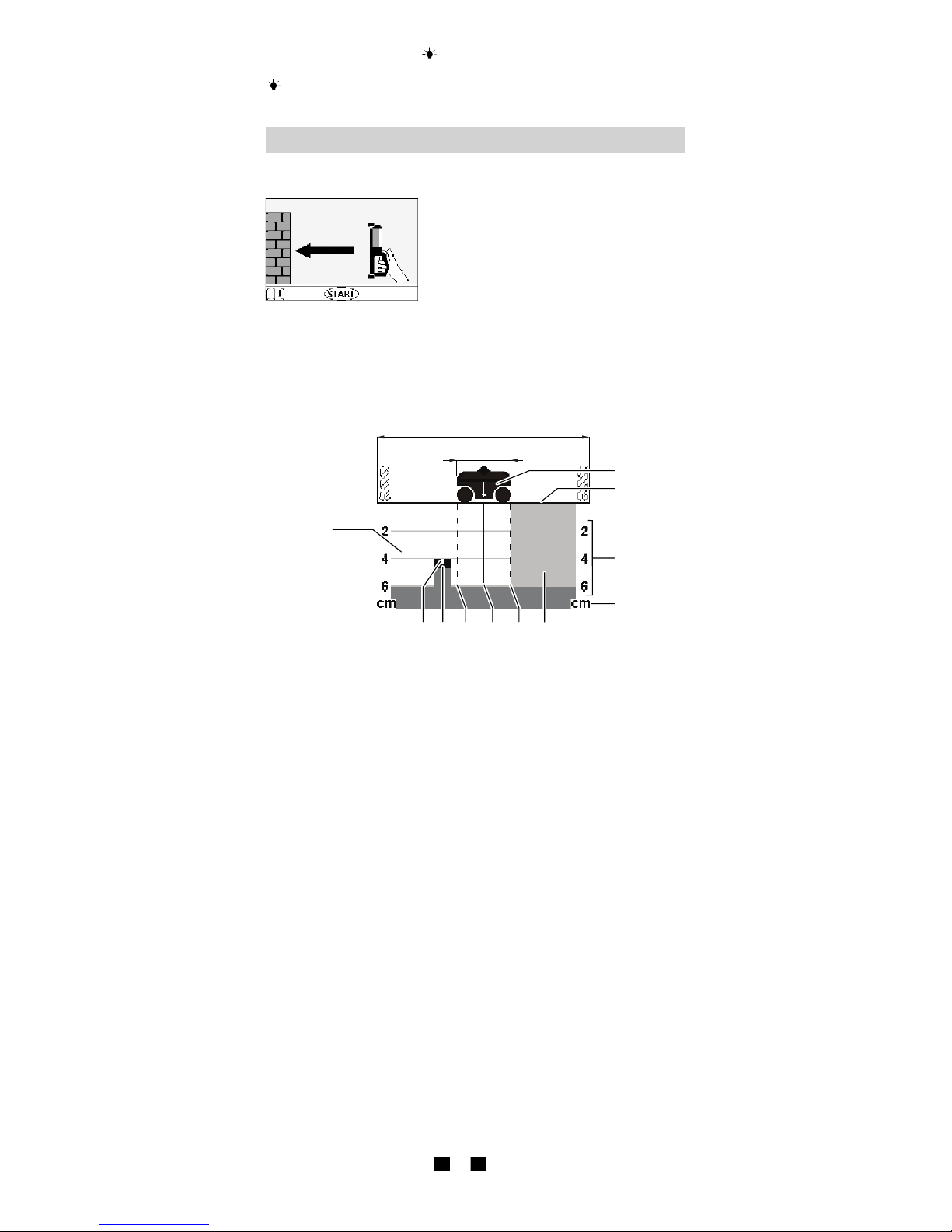
Wurde ein Objekt in der Wand gefunden, erscheint eine schwarze Markierung i im weißen Bereich k. Wie tief gebohrt werden kann, ist an der
Tiefenskala c im Display ablesbar.
Beispiel: In der obigen Anzeige befindet sich ein Objekt links neben
dem Gerät. An dieser Stelle kann bis 4 cm tief gebohrt werden.
Um Objekte zu orten, ist einmaliges Überfahren der Messfläche ausreichend.
Wurde kein Objekt gefunden, Bewegung über die Wand quer zur
ursprünglichen Messrichtung wiederholen (siehe Funktionsweise).
Um ein gefundenes Objekt genau lokalisieren und markieren zu können, Gerät, ohne es von der Wand abzusetzen, über die Messfläche
zurückbewegen (siehe auch Lokalisierung von Objekten).
Der Verlauf des gefundenen Objektes in der Wand kann festgestellt
werden, wenn mehrere Messstrecken versetzt nacheinander abgefahren werden (siehe Beispiele für Messergebnisse und ). Dazu die
jeweiligen Messpunkte markieren und verbinden.
Durch Drücken der Taste „start“ 6 kann die Anzeige der gefundenen
Objekte jederzeit gelöscht und eine neue Messung gestartet werden.
Messvorgang
≈ 350 mm
d
c
ihfgfe
k
a
≈ 100 mm
b
A B
Deutsch–5
1 609 929 C66 • (02.03) T
Wird das Gerät während einer Messung
von der Wand abgehoben, dann bleibt
das letzte Messergebnis im Display erhalten. Wird das Gerät wieder auf die Wand
aufgesetzt, startet die Messung von
neuem.
Beispiele für Messergebnisse (siehe Ausklappseite)
Objekt verläuft senkrecht in der Wand
Bei mehreren waagerechten Messstrecken untereinander wird jeweils
ein Objekt angezeigt. Die Markierungen des Objektes liegen senkrecht
untereinander. Bei senkrechten Messstrecken im gleichen Bereich gibt
es keine Anzeige.
Objekt verläuft waagerecht in der Wand
Bei waagerechten Messtrecken im zu untersuchenden Bereich gibt es
keine Anzeige. Bei mehreren senkrechten Messstrecken im gleichen
Bereich nebeneinander wird jeweils ein Objekt angezeigt. Die Markierungen des Objektes liegen waagerecht nebeneinander.
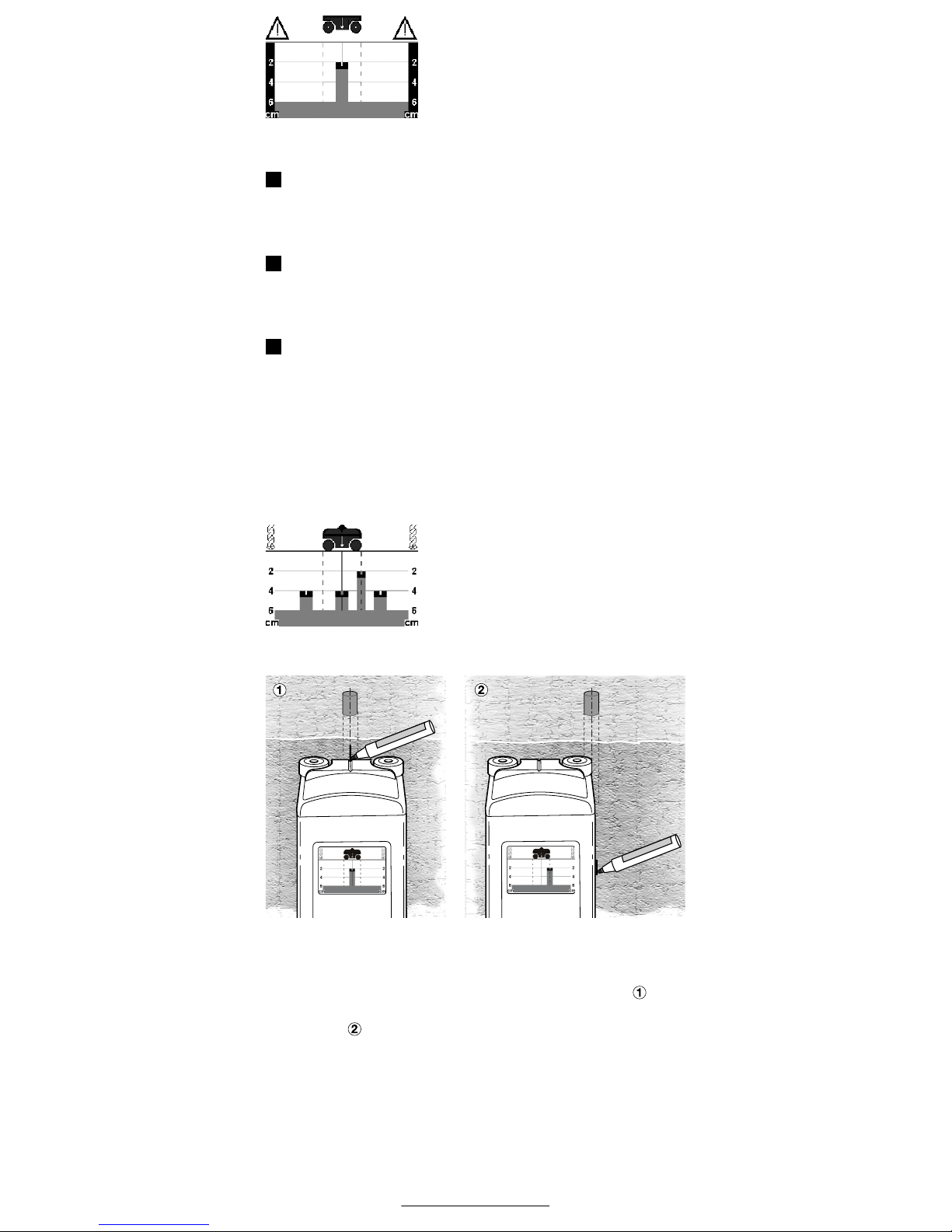
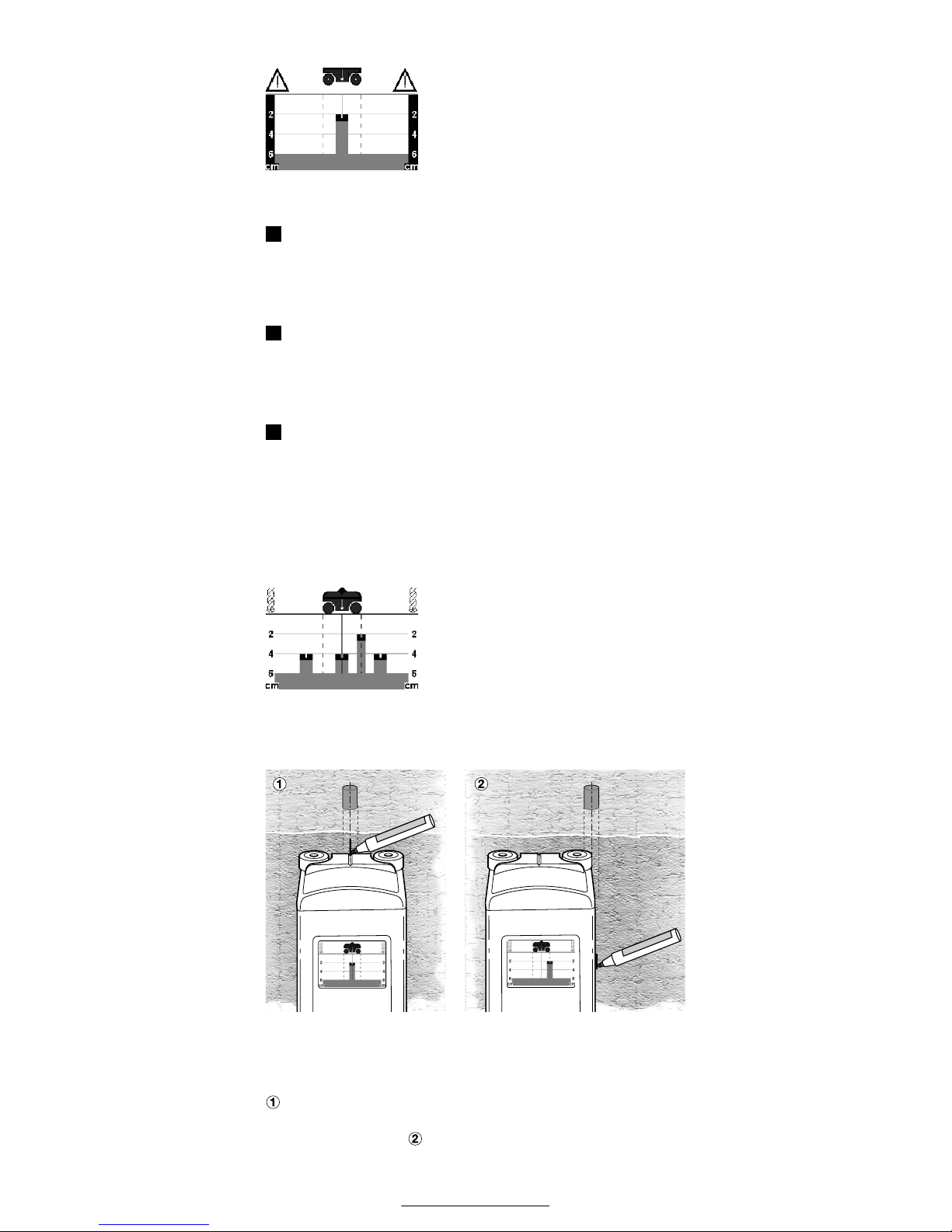
Punktuelles Objekt (z.B. Schraube)
Bei mehreren waagerechten und senkrechten Messstrecken über der
gleichen Fläche wird jeweils nur an einer einzigen Stelle ein Objekt angezeigt. Die Markierungen des Objektes kreuzen sich an der gleichen
Stelle.
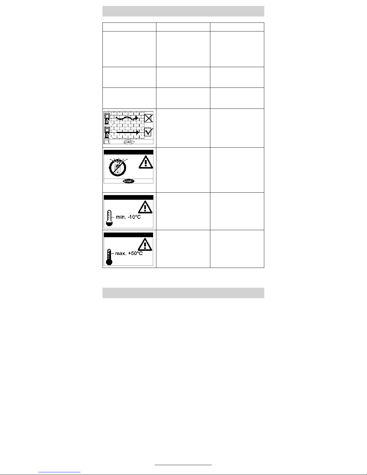
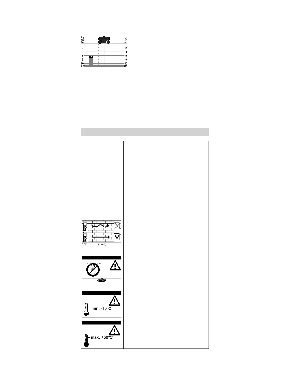
Anhand der Messergebnisse können in regelmäßigen Abständen
mehrfach vorhandene Objekte (z.B. Armierungseisen, Hohlräume in
Hohlblocksteinen) von Einzelobjekten (z.B. Netzleitungen) unterschieden werden. Dazu einen größeren Messbereich abfahren und die Ergebnisse vergleichen.
Beispiel: Im Bild sind drei regelmäßig angeordnete Objekte mit einer zugehörigen
Bohrtiefe von 4 cm Tiefe erkennbar, die
durch ihre Lage und Tiefe auf Armierungseisen schließen lassen. Beim vierten Objekt in 2 cm Tiefe kann es sich z.B. um
eine Netzleitung handeln.
Lokalisierung von Objekten
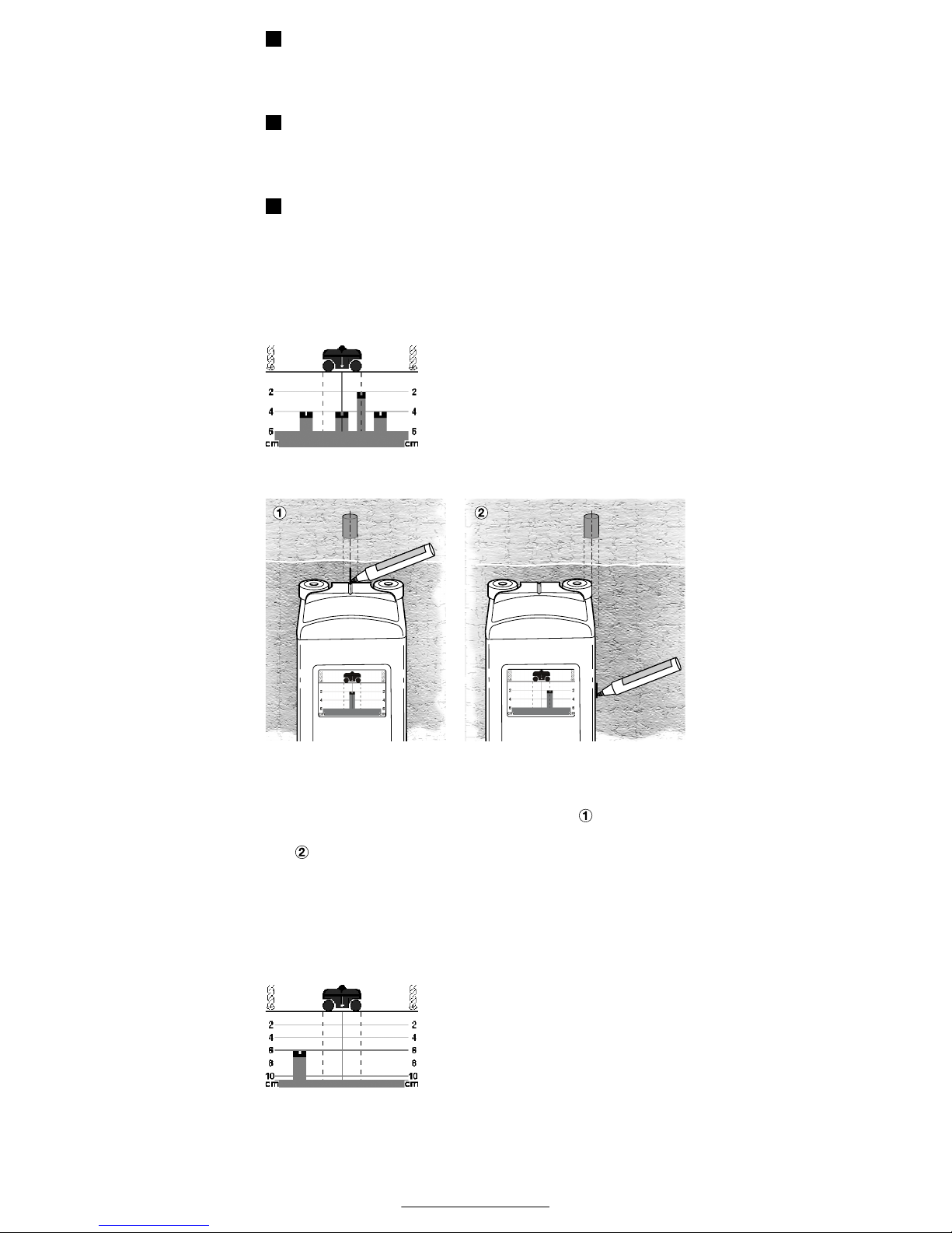
Zur Lokalisierung eines Objektes das Gerät so lange in Fahrtrichtung
auf das Objekt zu bewegen, bis die Mittellinie g des Gerätes im Display
genau über der Mittellinie h des gefundenen Objektes liegt. Das Objekt
befindet sich dann genau unter der Mitte des Gerätes. Mit Hilfe der Ausrichthilfe 9 kann die Lage des Objektes markiert werden (Bild ).
Die Markierung kann ebenfalls mit Hilfe der Außenkanten des Gerätes
erfolgen (Bild , Bezug auf Linien f).
Änderung der Messanzeige
Das Gerät zeigt die Messergebnisse standardmäßig bis zu einer Tiefe
von 6 cm an. Diese Einstellung ist besonders für Leichtbau-, Holz- oder
Hohlziegelwände geeignet, bei denen Störobjekte wie z.B. Hohlräume
die Messanzeige ab 6 cm Tiefe unübersichtlich werden lassen.
A
B
C
Deutsch–6
1 609 929 C66 • (02.03) T
Durch Drücken der Taste „mode“ 8 während einer Messung kann die Anzeige der
Messergebnisse auf 10 cm Tiefe erweitert
werden. Dies empfiehlt sich besonders
bei Beton und anderen massiven Wandmaterialien ohne Lufteinschlüsse (wie z.B.
Kalksandstein-Vollblock).
Durch erneutes Drücken der Taste „mode“ 8 schaltet das Gerät wieder auf die Standardeinstellung zurück. Die gewählte Einstellung bleibt
bis zum Ausschalten des Gerätes erhalten.
Nach erneutem Einschalten des Gerätes wird wieder die Standardmesstiefe von 6 cm angezeigt.
Vor jedem Gebrauch das Gerät überprüfen. Bei sichtbaren
Beschädigungen oder losen Teilen im Inneren des Gerätes ist
eine sichere Funktion nicht mehr gewährleistet.
Gerät stets sauber und trocken halten.
Verschmutzungen mit feuchtem, weichem Tuch abwischen. Keine
scharfen Reinigungs- oder Lösemittel verwenden. Vor erneutem Gebrauch Gerät trockenreiben.
Fehler – Ursachen und Abhilfe
Fehler/Anzeige Ursache Abhilfe
Gerät kann nicht eingeschaltet werden.
Batterien leer. Neue Batterien einset-
zen.
Batterien mit falscher
Polung eingelegt.
Richtige Lage der Batterien prüfen.
Gerät ist eingeschaltet
und reagiert nicht
mehr auf Eingaben.
Batterien herausnehmen und wieder einsetzen.
Display schwarz. Gerät zu stark er-
wärmt bzw. der direkten Sonnenstrahlung
ausgesetzt.
Abwarten, bis der zulässige Temperaturbereich erreicht ist.
Gerät mit zu hoher
Geschwindigkeit bewegt.
Gerät langsamer über
die Wand bewegen.
Gerät wurde nicht geradlinig über die Wand
bewegt oder einzelne
Räder hatten keinen
Wandkontakt.
Gerät nochmals geradlinig über die Wand
bewegen, auf Wandkontakt aller Räder
achten.
Äußere Einflüsse wie
Handy, Mikrowelle
oder Mobilfunksendemasten stören die
Messung.
Störeinflüsse, wenn
möglich, abschalten.
Neue Messung durch
Drücken der Taste
„start“ 6 beginnen.
Temperatur zu niedrig.
Abwarten, bis der zulässige Temperaturbereich erreicht ist.
Temperatur zu hoch. Abwarten, bis der zu-
lässige Temperaturbereich erreicht ist.
Wartung und Reinigung

Deutsch–7
1 609 929 C66 • (02.03) T
Räder wechseln
Defekte oder stark abgenutzte Räder auswechseln. Dazu Schraube 1
mit Torx-Schraubendreher (Größe 7) lösen, Rad 2 wechseln und
Schraube 1 wieder gut festziehen.
Sollte das Gerät trotz sorgfältiger Herstell- und Prüfverfahren einmal
ausfallen, ist die Reparatur von einer autorisierten Kundendienststelle
für Bosch-Elektrowerkzeuge ausführen zu lassen.
Bei allen Rückfragen und Ersatzteilbestellungen bitte unbedingt die 10stellige Bestellnummer laut Typenschild des Gerätes angeben.
Im Reparaturfall das Gerät in der Schutztasche 14 einsenden.
Rohstoffrückgewinnung statt Müllentsorgung
Gerät, Zubehör und Verpackung sollten einer umweltgerechten Wiederverwertung zugeführt werden.
Diese Anleitung ist aus chlorfrei gefertigtem Recycling-Papier hergestellt.
Zum sortenreinen Recycling sind Kunststoffteile gekennzeichnet.
Verbrauchte Akkus/Batterien nicht in den Hausmüll, ins Feuer oder ins
Wasser werfen, sondern – den geltenden gesetzlichen Bestimmungen
entsprechend – umweltgerecht entsorgen.
In Deutschland sind nicht mehr gebrauchsfähige Geräte zum Recycling
beim Handel abzugeben oder (ausreichend frankiert) direkt einzuschicken an:
Recyclingzentrum Elektrowerkzeuge
Osteroder Landstr. 3
D-37589 Kalefeld
www.powertool-portal.de, das Internetportal für Handwerker und
Heimwerker
www.ewbc.de, der Informationspool für Handwerk und Ausbildung
Deutschland
Robert Bosch GmbH
Servicezentrum Elektrowerkzeuge
Zur Luhne 2
D-37589 Kalefeld
✆ Service: . . . . . . . . . . . . . . . . . . . . . . . . . . . . . . . 01 80/3 35 54 99
Fax. . . . . . . . . . . . . . . . . . . . . . . . . . . . . . . . + 49 (0) 55 53/20 22 37
✆ Kundenberater: . . . . . . . . . . . . . . . . . . . . . . . . . 01 80/3 33 57 99
Österreich
ABE Service GmbH
Jochen-Rindt-Straße 1
A-1232 Wien
✆ Service: . . . . . . . . . . . . . . . . . . . . . . . . . . . . . . . +43 (0)1/61 03 80
Fax. . . . . . . . . . . . . . . . . . . . . . . . . . . . . . . . . . +43 (0)1/61 03 84 91
✆ Kundenberater: . . . . . . . . . . . . . . . . . . . . . +43 (0)1/7 97 22 30 66
E-Mail: abe@abe-service.co.at
Schweiz
Robert Bosch AG
Kundendienst Elektrowerkzeuge
Industriestrasse 31
CH-8112 Otelfingen
✆ Service: . . . . . . . . . . . . . . . . . . . . . . . . . . . . . . +41 (0)1/847 16 16
✆ Kundenberater: . . . . . . . . . . . . . . . Grüne Nummer 0 800 55 11 55
Änderungen vorbehalten
Umweltschutz
Service und Kundenberater

English–1
1 609 929 C66 • (02.03) T
Working safely with this unit is possible only when
the operating and safety information are read
completely and the instructions contained therein
are strictly followed.
The numbering of the product elements refers to the illustration on the
fold-out page.
1 Screw
2 Wheel
3 Display
4 Display lighting button
5 “on/off” button
6 “start” measurement button
7 Handle
8 “mode” button
9 Aligning aid
10 Sensor area
11 Battery compartment cover
12 Battery compartment latch
13 Serial number
14 Protective bag
* Depending on the material and size of the object as well as the condition of the
base material (see Functional Method)
** see graphic:
For Your Safety
Product Elements
Product Specifications
Universal Detection Unit Wallscanner D-tect 100
Order number 0 601 095 003
Maximum measuring depth* [cm] 10
Measurement accuracy to the object middle point a** [mm] ±5
Accuracy of the indicated allowable
drilling depth b** [mm] ±5
Minimum distance between two
neighbouring objects c** [mm] 40
Operating temperature [°C] –10 … +50
Storage temperature [°C] –20 … +70
Batteries
Rechargeable batteries
4 x 1,5 V LR6 (AA)
4 x 1,2 V KR6 (AA)
Operating time (alkali-manganese
batteries), approx. [h] 13
Protection class
(according to IEC 529)
IP 54 (dust and splash
water protection)
Weight (with batteries) approx. [g] 800
a
b
c

English–2
1 609 929 C66 • (02.03) T
The serial number 13 for positive identification of your unit is located on
the nameplate on the underside of the case.
Please observe the order number of your unit. The trade names of the
individual units may vary.
The unit is intended for detecting objects such as, for example, metal,
wood, plastic pipes, wiring and cable in walls, ceilings and floors as well
as the indication of the allowable drilling depth with respect to the detected objects.
■ Protect the unit from moisture and direct sunrays.
■ In order not to influence the measured results, no stickers or name-
plates may be attached to the sensor area 10 on the back of the
unit, especially nameplates of metal.
■ If the unit is not used for a long period, the batteries must be re-
moved (danger of corrosion).
■ Transport and store the unit in the protective bag 14.
Use alkali-manganese or rechargeable batteries exclusively.
To open the battery compartment cover 11, press the latch 12 in direction of the arrow (a) and lift up. Remove the battery compartment cover
(b). Insert the batteries provided. (See the illustration on the fold-out
page.)
When inserting the batteries, pay attention to the correct polarisation.
When the small battery symbol appears in the upper left of the display, the
unit can still be operated for approx.
30 min when using alkali-manganese batteries (shorter period for rechargeable
batteries).
If the indication shown here appears in the
display, the batteries must be replaced.
Measurements are no longer possible.
Always replace the complete set of battery. Use only batteries of a single manufacturer with the same capacity.
With the unit, the base material in the sensor area 10 in the measurement direction
A is checked to the maximum measuring
depth. Measurement is possible only during movement of the unit in the direction
of travel B and for a distance of at least
8 cm.
Move the unit in a straight line with
light pressure over the wall so that
the wheels remain in contact with the
wall. Objects are detected that differ
from the material of the wall. In the
display, the allowable drilling depth in
each case is indicated.
Optimum results are achieved when the
measured distance is at least 40 cm and
the unit is moved over the entire location
to be checked.
Intended Use
Protection of the Unit
Inserting/Replacing the Batteries
Functional Method
A
B
B
10

English–3
1 609 929 C66 • (02.03) T
Objects are found reliably only when they
run transversely to the direction of
movement of the unit.
Therefore, always move crossways
over the area to be checked.
Objects that are considerably larger than
the unit can also be indicated with parallel
movements.
The indication of the unit is optimised for
the highest possible safety for drilling.
Drilling can be performed to the maximum
drilling depth determined.
If several objects are located one over the other in the wall, the object
is indicated in the display that is nearest to the surface.
Detectable objects:
– Metal of all types (e.g. steel, copper, aluminium)
– Plastic pipes (e.g. water pipes, empty pipes)
– Wood (e.g. beams)
– Electrical wiring (independent of whether carrying voltage or not)
– Three phase mains wiring (e.g. to the stove)
– Extra-low voltage wiring (e.g. telephone, door bell)
– Hollow space
Measurements possible in:
– Concrete/reinforced concrete
– Masonry blocks (brick, porous concrete, foam concrete, pumice
concrete)
– Light construction walls
– as well as under surfaces such as stucco, tiles, wallpaper, parquet,
carpet
Special Measuring Cases
Under unfavourable conditions, the unit cannot detect certain objects
as a result of the principle involved, for example:
– Empty plastic pipes in hollow spaces are not detected.
– Metal surfaces and damp surfaces with high water content cannot
be penetrated.
– Damp areas in a wall can possibly be indicated as an object (e.g.
for high water content).
– For walls made up of several layers, e.g. with wall covering, possi-
bly only the first boundary layer (e.g. hollow space behind the wall
covering) is indicated.
– Hollow spaces in a wall are indicated as objects.
– Large cylindrical objects (e.g., plastic or water pipes) can appear in
the display smaller than they actually are.
Before using the unit, ensure that the sensor area 10 is not
moist. Wipe the unit dry with a cloth as necessary.
Switching On/Off
Switching on:
Press the “on/off” button 5 or the “start” button 6. The illuminated
start display appears.
Before beginning the measurement (see Measurement Procedure), an
explanation of the functional method of the unit can be called up in the
display 3 by pressing the “mode” button 8.
Switching off:
Press the “on/off” button 5.
After approx. 5 min without performing a measurement, the unit
switches off automatically to save the batteries.
Display Lighting
In the dark, press the display lighting button 4. The display is then
lit. To switch off the lighting, press the button 4 again.
Putting into Operation

English–4
1 609 929 C66 • (02.03) T
The unit does not display the wall as transparent but rather in
cross section.
If the unit was not switched on while being
held against the wall, a prompt appears in
the display to place the unit against the
wall for measuring.
Move the unit in the direction of travel (see Functional Method) over the
wall. The measurement results are indicated immediately in the display
3. To ensure correct measurement results, the unit must be moved
over a distance of at least 8 cm.
During the measurement, the following display elements appear:
Display Elements
a Cross section of the unit
b Wall surface
c Depth scale for allowable drilling depth
d Dimensional unit for the depth scale
e Grey: Area not yet examined
f Outer edges of the unit
g Middle line of the unit whose position corresponds to the aligning
aid 9 on the unit
h Middle line of the object that was found in the wall
i Black: Object found in the wall
k White: Already examined area
If an object is found in the wall, a black mark i appears in the white area
k. The depth to which drilling can take place is readable on the depth
scale c in the display.
Example: In the display above, an object is located on the left next to
the unit. At this position, drilling to a depth of 4 cm can be performed.
To detect objects, one pass over the measured surface is adequate.
If no object was found, repeat the movement over the wall transversely
to the original measurement direction (see Functional Method).
To exactly localise and mark an object found, move the unit back over
the measured surface without lifting it from the wall (see also Localisa-
tion of Objects).
The extent of the object found in the wall can be determined when several offset measurement passes are made shifted with respect to each
other (see Example for Measurement Results and ). For this purpose, mark and connect the respective measured points.
By pressing the “start” button 6, the display of the objects found can
be deleted at any time and a new measurement started.
If the unit is lifted away from the wall during a measurement, the last measured results remain in the display. If the unit is
placed against the wall again, the measurement starts anew.
Measuring Procedure
≈ 350 mm
d
c
ihfgfe
k
a
≈ 100 mm
b
A
B
English–5
1 609 929 C66 • (02.03) T
Examples of Measured Results (see fold-out page)
An object runs vertically in the wall
With several horizontal measuring passes one under the other, an object is indicated in each case. The markings of the object are vertically
one below the other. For vertical measuring passes in the same area,
no indication results.
An object runs horizontally in the wall
For horizontal passes in the examined area, no indication results. For
several vertical measuring passes side by side in the same area, an object is indicated in each case. The marking of the object are next to
each other.
Point-shaped object (e.g. screw)
For several horizontal and vertical measuring passes over the same area, an object is indicated only at a single location in each direction. The
markings of the object cross each other at the same location.
On the basis of the measured results, several objects occurring at regular intervals (e.g. reinforcing iron, hollow space in blocks) can be distinguished from individual objects (e.g. mains wiring). For this purpose,
make passes over a large measurement area and compare the results.
Example: In the illustration, three evenly
spaced objects with an associated drilling
depth of 4 cm are recognisable that, as a
result of their position and depth, can be
assumed to be reinforcing iron. The fourth
object at 2 cm depth can be, for example,
a mains cable.
Localisation of Objects
For the localisation of an object, move the unit in the direction of travel
toward the object until the middle line g of the unit in the display is exactly over the middle line h of the object found. The object in then located exactly under the middle of the unit. With the help of the aligning
aid 9, the position of the object can be marked (Fig. ).
The marking can also be made with the aid of the outer edge of the unit
(Fig. , with reference to line f).
Changing the Measurement Indication
The unit displays the measured results to a depth of 6 cm as standard.
This setting is especially suitable for light construction, wood or wooden tile walls for which interfering objects such as, for example, empty
spaces make the measurement display unreliable for depths greater
than 6 cm.
By pressing the “mode” button 8 during
the measurement, the display of the
measured results can be extended to
10 cm depth. This is recommended especially for concrete and other solid wall
materials without air pockets (such as, for
example, solid lime-sandstone blocks).
With renewed pressing of the “mode” button 8, the unit switches back
again to the standard setting. The selected setting remains active until
the unit is switched off.
After renewed switching on of the unit, the standard measurement
depth of 6 cm is again displayed.
A
B
C
English–6
1 609 929 C66 • (02.03) T
Before each use, check the unit. For visible damage or loose
parts in the interior of the unit, reliable functioning is no longer
ensured.
Always keep the unit clean and dry.
Wipe off dirt with a damp soft cloth. Do not use aggressive cleaning
agents or solvents. Wipe dry before renewed usage.
Replacing Wheels
Replace defective or heavily worn wheels. For this purpose, loosen the
screw 1 with a Torx screwdriver (size 7), replace the wheel 2 and firmly
retighten the screw 1.
If the unit should fail despite the care taken in manufacture and testing,
repair should be carried out by an authorised customer services agent
for Bosch power tools.
For all correspondence and spare parts orders, always include the 10digit order number of the unit.
In case of repair, send in the unit in the protective bag 14.
Error – Cause and Correction
Error/Indication Cause Correction
The unit can not be
switched on.
Batteries are empty. Insert new batteries.
Batteries have been
inserted with the
wrong polarity.
Check the batteries
for correct position.
The unit is switched
on but no longer react
to inputs.
Remove and reinsert
the batteries.
The display is dark. The unit is too hot,
e.g. subjected to direct sunlight.
Wait until the allowable temperature range
is reached.
The unit was not
moved over the wall in
a straight line or the individual wheels had
no contact with the
wall.
Move the unit again
over the wall in a
straight line while taking care that all wheels
are in contact with the
wall.
External influences
such as mobile
phones, microwave
equipment or mobile
communication masts
are interfering with the
measurement.
Switch off interference
when possible. Begin
a new measurement
by pressing the
“start” button 6.
The temperature is
too low.
Wait until the allowable temperature range
is reached.
The temperature is
too high.
Wait until the allowable temperature range
is reached.
Maintenance and Cleaning

English–7
1 609 929 C66 • (02.03) T
Recycle raw materials instead of disposing as waste.
Unit, accessories and packaging should be sorted for environmentfriendly recycling.
These instructions are printed on recycled paper manufactured without
chlorine.
The plastic components are labelled for categorized recycling.
Do not throw used batteries into household waste, fire or water, but
rather – according to the applicable legal regulations – dispose of in an
environmentally friendly manner.
Great Britain
Robert Bosch Ltd. (B.S.C.)
P.O. Box 98
Broadwater Park
North Orbital Road
Denham-Uxbridge
GB-Middlesex UB 9 5HJ
✆ Service . . . . . . . . . . . . . . . . . . . . . . . . . . . +44 (0) 18 95/83 87 82
✆ Advice line . . . . . . . . . . . . . . . . . . . . . . . . . +44 (0) 18 95 / 83 87 91
Fax. . . . . . . . . . . . . . . . . . . . . . . . . . . . . . . . . +44 (0) 18 95/83 87 89
Ireland
Beaver Distribution Ltd.
Greenhills Road
IRL-Tallaght-Dublin 24
✆ Service . . . . . . . . . . . . . . . . . . . . . . . . . . . . . + 353 (0)1/414 9400
Fax. . . . . . . . . . . . . . . . . . . . . . . . . . . . . . . . . . . + 353 (0)1/459 8030
Australia
Robert Bosch Australia L.t.d.
RBAU/SBT2
1555 Centre Road
P.O. Box 66 Clayton
AUS-3168 Clayton/Victoria
✆. . . . . . . . . . . . . . . . . . . . . . . . . . . . . . . . . . . +61 (0)1/800 804 777
Fax. . . . . . . . . . . . . . . . . . . . . . . . . . . . . . . . . . +61 (0)1/800 819 520
www.bosch.com.au
E-Mail: CustomerSupportSPT@au.bosch.com
New Zealand
Robert Bosch Limited
14-16 Constellation Drive
Mairangi Bay
Auckland
New Zealand
✆. . . . . . . . . . . . . . . . . . . . . . . . . . . . . . . . . . . . +64 (0)9/47 86 158
Fax. . . . . . . . . . . . . . . . . . . . . . . . . . . . . . . . . . . . +64 (0)9/47 82 914
Specification subject to alteration without notice
Environmental Protection
Service and Customer Advice

Français–1
1 609 929 C66 • (02.03) T
Pour travailler sans risque avec cet appareil, lire
intégralement au préalable les instructions de service et les remarques concernant la sécurité. Respecter scrupuleusement les indications et les consignes qui y sont données.
La numérotation des éléments de l’appareil se rapporte aux figures représentant l’appareil sur le volet dépliant.
1 Vis
2 Roue
3 Afficheur
4 Touche d’éclairage de l’afficheur
5 Interrupteur Marche/Arrêt « on/off »
6 Touche de mesure « start »
7 Poignée
8 Touche « mode »
9 Traits de visée (ligne médiane de l’appareil)
10 Surface de mesure
11 Couvercle du logement des piles
12 Ergot de verrouillage du couvercle du compartiment des piles
13 Numéro de série
14 Etui de protection
* selon le matériau et la taille des objets ainsi que du matériau et de l’état du support (cf. Mode de fonctionnement)
** cf. graphique:
Pour votre sécurité
Eléments de l’appareil
Caractéristiques techniques
Détecteur universel Wallscanner D-tect 100
Référence 0 601 095 003
Profondeur de mesure max.* [cm] 10
Précision de mesure par rapport
au centre de l’objet a** [mm] ±5
Précision de la profondeur de
perçage admissible affichée b** [mm] ±5
Distance minimale entre deux
objets voisins c** [mm] 40
Température de service [°C] –10 … +50
Température de stockage [°C] –20 … +70
Piles
Accus
4 x 1,5 V LR6 (AA)
4 x 1,2 V KR6 (AA)
Autonomie (durée de fonctionnement
avec piles alcalines au manganèse) env. [h] 13
Type de protection (selon IEC 529) IP 54 (protection con-
tre les poussières et
les projections d’eau)
Poids (avec piles) env. [g] 800
a
b
c
Français–2
1 609 929 C66 • (02.03) T
Le numéro de série 13 de votre appareil est précisé sur la plaque signalétique apposée sur la face inférieure du carter.
Faire attention au numéro de référence de l’appareil. Les désignations
commerciales des différents appareils peuvent varier.
Cet appareil a été conçu pour rechercher des objets (objets en métaux,
en bois, tubes ou gaines plastiques, conduites, câbles, par exemple)
dissimulés dans les parois, les plafonds et planchers. Il permet également d’afficher de manière fiable la profondeur de perçage admissible, par rapport aux objets effectivement localisés.
■ Ne pas exposer l’appareil à l’action directe du soleil. Ne pas l’expo-
ser à l’humidité.
■ Afin de ne pas altérer les résultats des mesures, ne pas coller
d’autocollant ni appliquer de plaquette métallique ou d’aucune
autre sorte sur la surface de mesure 10.
■ Lorsque l’appareil reste inutilisé pour une période assez longue, ex-
traire les piles (risque, sinon, de corrosion).
■ Transporter et ranger l’appareil dans son étui de protection 14.
Utiliser uniquement des piles alcalines au manganèse ou des accus.
Pour ouvrir le couvercle du compartiment de piles 11, repousser l’ergot
de verrouillage 12 dans le sens de la flèche (a). Retirer le couvercle (b).
Mettre en place les piles fournies. (Cf. la figure sur le volet dépliant.)
Mettre les piles en place en veillant à respecter les polarités.
Lorsque le petit témoin de décharge des
piles apparaît en haut à gauche sur
l’afficheur, l’appareil peut encore, s’il est
utilisé avec des piles alcalines au manganèse, fonctionner pendant environ
30 minutes (avec des accus, ce délai est
plus faible).
Lorsque les symboles ci-contre apparaissent, les piles doivent être remplacées.
Aucune mesure fiable n’est plus possible.
Toujours remplacer le jeu de piles complet. Utiliser toujours un jeu homogène de
piles (fabricant et capacité identiques).
L’appareil permet de contrôler la paroi
considérée sur la surface de mesure 10
jusqu’à la profondeur de mesure maximale
dans la direction de mesure A. La mesure
n’est effective que lors du déplacement de
l’appareil sur une distance minimale de
mesure de 8 cm dans l’axe de balayage B.
Toujours déplacer l’appareil en ligne
droite en exerçant une légère pression de manière à ce que les roues
restent bien en contact avec la paroi.
Les objets dont le matériau constitutif
est différent de celui de la paroi sont
détectés. Sur l’afficheur, c’est cependant toujours la profondeur de perçage admissible qui est affichée.
Les meilleures performances s’obtiennent
lorsque la distance de mesure est égale ou
dépasse 40 cm et que l’appareil est déplacé sur l’ensemble de la surface à
contrôler.
Utilisation conforme
Protection de l’appareil
Mise en place/changement des piles
Mode de fonctionnement
A
B
B
10
Français–3
1 609 929 C66 • (02.03) T
Seuls les objets disposés perpendicu-
lairement à la direction de balayage sont
détectés de manière fiable.
Inspecter donc toujours la surface à
contrôler selon deux directions de
balayage perpendiculaires.
Les objets significativement plus gros que
l’appareil lui-même peuvent aussi être détectés lors de déplacements parallèles.
L’affichage de l’appareil a été optimisé
pour garantir la plus grande sécurité de
perçage possible. Il est possible de percer jusqu’à la profondeur de perçage
maximale déterminée.
Lorsque plusieurs objets se trouvent superposés dans l’épaisseur de la
paroi, l’objet affiché est celui qui se trouve le plus près de la surface.
Objets détectables :
– objets métalliques de toute nature (acier, cuivre, aluminium, par
exemple),
– tubes en plastiques (conduites d’eau, tubes vides, par exemple),
– morceaux de bois (poutres, par exemple),
– lignes électriques (qu’elles soient sous tension ou non),
– lignes électriques triphasées (d’une cuisinière électrique, par exem-
ple),
– lignes électriques à courants faibles (ligne de téléphone, ligne de la
sonnerie électrique, par exemple),
– cavités.
Mesures possibles :
– dans le béton/le béton armé,
– dans les maçonneries (brique, béton cellulaire, béton expansé,
pierre ponce),
– dans les parois préfabriquées,
– sous les surfaces d’enduits, de carrelages, de tapisseries murales,
les parquets, les tapis.
Cas de mesures spécifiques
De par son principe de fonctionnement même, l’appareil n’est, dans
certaines circonstances défavorables, pas en mesure de localiser de
manière fiable certains objets. Exemples :
– Les conduites en plastiques dans les cavités ne sont pas détec-
tées.
– Les surfaces métalliques et les surfaces humides dont la teneur en
eau est élevée restent imperméables à l’appareil.
– Les zones humides peuvent, dans certaines circonstances (taux
d’humidité élevé, par exemple), être identifiées comme des objets.
– Dans le cas où la paroi est constituée de plusieurs épaisseurs dis-
tinctes (habillage mural, par exemple), il peut arriver que seule la
première épaisseur (espace interstitiel derrière l’habillage) soit dé-
tectée.
– Les cavités d’une paroi sont affichées comme des objets.
– Les objets cylindriques de diamètres importants (tubes en plasti-
ques, conduites d’eau en plastique, par exemple) peuvent sembler
plus étroits sur l’afficheur qu’ils ne sont en réalité.
Avant de mettre l’appareil en marche, s’assurer que la surface
de mesure 10 n’est pas humide. Si nécessaire, essuyer l’appareil
avec un chiffon sec.
Mise en marche/Arrêt
Marche :
Enfoncer l’interrupteur Marche/Arrêt « on/off » 5 ou la touche « start »
6. L’écran de départ éclairé apparaît.
Avant de lancer la mesure (cf. Déroulement de la mesure), il est possible, en appuyant sur la touche « mode » 8 de faire apparaître sur l’afficheur 3 quelques explications quant au fonctionnement de l’appareil.
Arrêt :
Enfoncer la touche Marche/Arrêt « on/off » 5.
Au bout d’env. 5 min passées sans qu’une mesure n’ait été effectuée,
l’appareil s’arrête automatiquement afin de ménager les piles.
Mise en service
Français–4
1 609 929 C66 • (02.03) T
Eclairage de l’afficheur
Lorsque la lumière ambiante s’avère insuffisante, enfoncer la touche
d’éclairage de l’afficheur 4. Cela active l’éclairage de l’afficheur.
Pour désactiver cet éclairage, enfoncer une nouvelle fois la touche
4.
La vue qui apparaît sur l’afficheur de l’appareil n’est pas une vue
en coupe transversale mais une vue en coupe sagittale.
Si l’appareil est mis en marche alors qu’il
n’est pas appliqué contre une paroi, apparaît sur l’afficheur une invitation à l’appliquer pour mesure contre une paroi.
Déplacer l’appareil sur le mur dans l’axe de balayage (cf. Mode de fonc-
tionnement). Les résultats de mesure apparaissent immédiatement sur
l’afficheur 3. Pour garantir la qualité des résultats, l’appareil doit parcourir une distance minimale de 8 cm.
Pendant la mesure, les éléments d’affichage suivants apparaissent :
Eléments d’affichage
a Vue en coupe de l’appareil
b Surface de la paroi
c graduation de profondeur pour la détermination de la profondeur
de perçage admissible
d unité de mesure de la graduation
e gris : zone non encore balayée
f bords extérieurs de l’appareil
g ligne médiane de l’appareil (cette ligne correspond au trait de
visée 9 de l’appareil)
h ligne médiane de l’objet qui a été détecté dans le mur
i noir : objet détecté dans le mur
k blanc : zone déjà balayée
Lorsqu’un objet a été détecté, un repère noir i est affiché dans la zone
blanche k. La profondeur de perçage admissible se détermine via
l’échelle de profondeur c qui apparaît sur l’afficheur.
Exemple : dans la représentation ci-dessus un objet a été détecté à
gauche de l’appareil. A cet endroit, la profondeur de perçage admissible s’élève à 4 cm.
Pour localiser un objet, un seul balayage de la surface de mesure suffit.
Si aucun objet n’a été détecté, effectuer un balayage de la surface à
mesurer perpendiculairement au premier balayage (cf. Mode de fonc-
tionnement).
Pour localiser et repérer de manière précise un objet détecté, balayer
la surface à contrôler dans l’autre sens sans relever l’appareil (cf. également Localisation d’objets).
Le tracé de l’objet dans la paroi peut être déterminé en procédant à
plusieurs balayages décalés les uns par rapport aux autres (cf. Exem-
ples de résultats de mesure et ). Repérer les différents points de
mesure obtenus et les relier les uns aux autres.
Déroulement de la mesure
≈ 350 mm
d
c
ihfgfe
k
a
≈ 100 mm
b
A B
Français–5
1 609 929 C66 • (02.03) T
Le fait d’enfoncer la touche de mesure « start » 6 permet de faire disparaître, sur l’afficheur, les objets localisés et de relancer une nouvelle
mesure.
Lorsque l’appareil quitte le contact d’une
paroi pendant une mesure, le dernier résultat de mesure reste affiché sur l’afficheur. Lorsque l’appareil est de nouveau
appliqué contre la paroi, la mesure est reprise depuis le début.
Exemples de résultats de mesure (cf. le volet dépliant)
L’objet est disposé verticalement dans la paroi
Les balayages successifs horizontaux et décalés permettent d’afficher
la présence d’un objet. Les repérages de l’objet se situent verticalement les uns en dessous des autres. Les balayages successifs verticaux et décalés effectués sur la même zone ne permettent de détecter
la présence d’aucun objet.
L’objet est disposé horizontalement dans la paroi
Les balayages successifs horizontaux et décalés effectués sur la zone
à mesurer ne permettent de détecter la présence d’aucun objet. Les
balayages successifs verticaux et décalés permettent d’afficher la présence d’un objet. Les repérages de l’objet se situent horizontalement
les uns à côté des autres.
Objet ponctuel (vis, par exemple)
Des balayages successifs horizontaux et verticaux effectués sur la zone
à mesurer ne permettent de détecter la présence d’un objet qu’en un
seul point. Les repérages de l’objet se croisent en ce même point.
Les résultats de mesure permettent, le cas échéant, de distinguer plusieurs objets identiques régulièrement espacés (fers d’armatures, cavités, dans des parpaings) correspondants à des objets identiques (lignes électriques, par exemple). Se convaincre de la chose en balayant
une zone plus étendue et comparer les résultats obtenus.
Exemple : dans la représentation ci-contre, il a été détecté à 4 cm de profondeur
environ trois objets disposés régulièrement
les uns par rapport aux autres. La position
et la profondeur de ces objets laissent supposer qu’il s’agit de fers d’armature. Pour
ce qui est du quatrième objet détecté à
une profondeur de 2 cm, il s’agit sans doute d’une ligne électrique.
Localisation d’objets
Pour localiser un objet, déplacer l’appareil au-dessus de l’objet dans la
direction de balayage jusqu’à ce que sur l’afficheur la ligne médiane g
de l’appareil coïncide avec la ligne médiane h de l’objet détecté. L’objet
se situe alors exactement sous le milieu de l’appareil. Le trait de visée
9 permet à l’utilisateur de repérer la position de l’objet considéré (Fig.
).
Le marquage des objets peut également se faire via les bords extérieurs de l’appareil (Fig. , lignes de repérage f).
A
B
C
Français–6
1 609 929 C66 • (02.03) T
Modification de la profondeur d’affichage
Dans le mode d’affichage par défaut, les résultats de mesure sont affichés jusqu’à une profondeur de 6 cm. Ce réglage convient particulièrement bien aux parois de matériaux préfabriqués et aux parois en bois
ou en briques creuses dont les objets parasites (cavités, par exemple)
rendraient l’affichage trop complexe au-delà de 6 cm de profondeur.
Le fait d’enfoncer la touche « mode » 8
pendant une mesure, permet d’étendre la
profondeur d’affichage à 10 cm. Ce réglage s’avère souvent judicieux pour les
parois de béton et autres parois en matériau massif sans inclusion d’air d’aucune
sorte (parpaings massifs de grès argilocalcaire, par exemple).
Le fait d’enfoncer une nouvelle fois la touche « mode » 8 permet de revenir au réglage par défaut de la profondeur d’affichage. Le réglage sélectionné persiste sinon jusqu’à l’arrêt de l’appareil.
Après une remise sous tension de l’appareil, celui-ci est automatiquement réglé sur sa profondeur d’affichage par défaut (6 cm).
Défaut – Causes et remèdes
Défaut/Affichage Cause Remède
L’appareil ne peut être
mis en marche.
Piles déchargées. Mettre en place des
piles neuves.
Mise en place incorrecte des piles (polarités).
Contrôler les polarités.
L’appareil est en marche mais ne réagit pas
aux instructions qui lui
sont faites.
Sortir les piles puis les
remettre en place.
L’afficheur est noir. Surchauffe de l’appa-
reil, exposition directe
aux rayons du soleil.
Patienter jusqu’au retour à l’intérieur de la
plage de températures admissibles.
L’appareil n’a pas été
déplacé de manière
rectiligne sur la paroi
ou bien certaines
roues ne sont pas restées en contact avec
la paroi.
Déplacer l’appareil de
manière rectiligne sur
la paroi ; veiller à ce
que toutes les roues
restent en contact
avec la paroi.
Des éléments perturbateurs (téléphone
portable, four microondes ou bien poteau
relais pour téléphone
portable, par exemple)
gênent la mesure.
Couper, si possible,
l’alimentation des éléments perturbateurs.
Relancer la mesure en
enfonçant la touche
« start » 6.
Température trop faible.
Patienter jusqu’au retour à l’intérieur de la
plage de températures admissibles.
Température trop élevée.
Patienter jusqu’au retour à l’intérieur de la
plage de températures admissibles.
Français–7
1 609 929 C66 • (02.03) T
Contrôler l’appareil avant toute utilisation. En cas de dommages
externes visibles ou d’éléments mobiles à l’intérieur, le bon
fonctionnement ne peut plus être garanti.
Cet appareil doit toujours rester propre et sec.
Nettoyer les salissures en essuyant l’appareil avec un chiffon doux. Ne
pas utiliser de produits de nettoyage ni de solvants agressifs. Avant de
reprendre l’utilisation de l’appareil, l’essuyer toujours avec un chiffon sec.
Remplacement des roues
Remplacer les roues défectueuses ou trop fortement usées. Pour ce
faire, dévisser la vis 1 avec un tournevis à embout torx (taille 7), changer
la roue 2 et revisser et bien bloquer la vis 1.
Si, malgré tous les soins apportés à la fabrication et au contrôle de l’appareil, celui-ci devait avoir un défaut, la réparation ne doit être confiée
qu’à une station de service après-vente pour outillage Bosch agréée.
Pour toute demande de renseignement ou commande de pièces de rechange, nous préciser impérativement le numéro de référence à dix
chiffres de l’appareil.
En cas de réparation, expédier l’appareil dans son étui de protection 14.
Récupération des matières premières plutôt
qu’élimination des déchets
Les appareils, comme d’ailleurs leurs accessoires et
emballages, doivent pouvoir suivre chacun une voie de
recyclage appropriée.
Ce manuel d’instructions a été fabriqué à partir d’un papier recyclé
blanchi en l’absence de chlore.
Nos pièces plastiques ont ainsi été marquées en vue d’un recyclage sélectif des différents matériaux.
Ne pas jeter les accus ou les piles usagées dans une poubelle aux ordures ménagères, dans un feu ou dans l’eau. S’en débarrasser conformément aux dispositions légales en vigueur en respectant l’environnement.
France
Information par Minitel 11
Nom: Bosch Outillage
Loc: Saint Ouen
Dépt: 93
Robert Bosch France S.A.
Service Après-vente/Outillage
B.P. 67-50, Rue Ardoin
F-93402 St. Ouen Cedex
✆ Service conseil client :
Numéro Vert . . . . . . . . . . . . . . . . . . . . . . . . . . . . . . 0800 05 50 51
Belgique
Robert Bosch S.A.
After Sales Service Outillage
Rue Henri Genesse 1
BE-1070 Bruxelles
✆ . . . . . . . . . . . . . . . . . . . . . . . . . . . . . . . . . . . . +32 (0)2/525.50.29
Fax. . . . . . . . . . . . . . . . . . . . . . . . . . . . . . . . . . . . +32 (0)2/525.54.30
✆ Service conseil client : . . . . . . . . . . . . . . . . . . . +32 (0)2/ 525.53.07
E-Mail : Outillage.Gereedschappen@be.bosch.com
Suisse
Robert Bosch AG
Service après-vente/Outillage
Industriestrasse 31
CH-8112 Otelfingen
✆ . . . . . . . . . . . . . . . . . . . . . . . . . . . . . . . . . . . +41 (0)1/847 16 16
✆ Service conseil client :
Numéro Vert . . . . . . . . . . . . . . . . . . . . . . . . . . . . . 0 800 55 11 55
Sous réserve de modifications
Maintenance et nettoyage
Instructions de protection de l’environnement
Service Après-Vente
Español–1
1 609 929 C66 • (02.03) T
Vd. solamente puede trabajar sin peligro con el
aparato si lee íntegramente las instrucciones de
manejo y las indicaciones de seguridad,
ateniéndose estrictamente a las indicaciones allí
comprendidas.
La numeración de los elementos del aparato se refiere a su representación en la solapa.
1 Tornillo
2 Rueda
3 Display
4 Tecla de iluminación del display
5 Tecla de conexión/desconexión “on/off”
6 Tecla de medición “start”
7 Empuñadura
8 Tecla “mode”
9 Ayuda para nivelado
10 Área de captación del sensor
11 Tapa del alojamiento de las pilas
12 Enclavamiento de la tapa de las pilas
13 Número de serie
14 Estuche de protección
* dependiendo del material y tamaño del objeto, así como del tipo de material y
estado del material base (ver Modo de funcionamiento)
** ver figura:
Para su seguridad
Elementos del aparato
Características técnicas
Detector universal Wallscanner D-tect 100
Número de pedido 0 601 095 003
Profundidad de medición máx.* [cm] 10
Exactitud de medida al centro del
objeto a** [mm] ±5
Precisión de la profundidad de tala-
drado indicada b** [mm] ±5
Separación mínima entre dos obje-
tos adyacentes c** [mm] 40
Temperatura de operación [°C] –10 … +50
Temperatura de almacenaje [°C] –20 … +70
Pila
Acumulador
4 x 1,5 V LR6 (AA)
4 x 1,2 V KR6 (AA)
Autonomía aprox.
(pilas alcalinas-manganeso) [h] 13
Tipo de protección (según IEC 529) IP 54 (protegido contra
polvo y salpicaduras de
agua)
Peso (con pila) aprox. [g] 800
a
b
c

Español–2
1 609 929 C66 • (02.03) T
Sobre la placa de características en la base del aparato va marcado el
número de serie 13 de su aparato, que permite identificarlo de forma
unívoca.
Preste atención al nº de pedido de su máquina. Las denominaciones
comerciales en ciertas máquinas puede variar.
El aparato ha sido proyectado para detectar objetos como, p.ej., metales, madera, tubos de plástico, tuberías y cables, en paredes, techos
y suelos, así como para determinar la profundidad de taladrado admisible en el punto de localización de los objetos.
■ Proteger el aparato de la humedad y exposición directa al sol.
■ Para no afectar al resultado obtenido en la medición, no deberán fi-
jarse en el área del sensor 10 situado al dorso del aparato, ni etiquetas ni placas, especialmente si éstas fuesen metálicas.
■ Si tiene previsto no utilizar el aparato durante un tiempo prolongado,
deberán sacarse las pilas (riesgo de corrosión).
■ Al transportar o guardar el aparato emplear el estuche de protec-
ción 14.
Emplear exclusivamente pilas alcalinas-manganeso o acumuladores.
Para abrir la tapa del alojamiento de la pila 11 presionar el enclavamien-
to 12 en dirección de la flecha (a) y levantarla. Retirar la tapa del alojamiento de las pilas (b). Insertar las pilas que se adjuntan. (Ver representación en la solapa.)
Observar en ello la polaridad correcta de las pilas.
Al representarse el pequeño símbolo de la
pila en el margen superior izquierdo
del display puede continuar trabajándose
con el aparato aprox. 30 min, en caso de
estar empleando pilas alcalinas-manganeso (con acumuladores esta autonomía
es menor).
En caso de representarse en el display el
símbolo de exclamación mostrado al
margen, es necesario sustituir las pilas, ya
que en ese caso no es posible realizar
ninguna medición.
Sustituir siempre todas las pilas. Solamente usar pilas de un mismo fabricante
y capacidad.
El aparato explora el material base dentro
del área del sensor 10 en el sentido de
medición A hasta la profundidad de captación máxima. Solamente se realiza la
medición, si el aparato se desplaza en el
sentido B cubriendo un tramo de medición mínimo de 8 cm.
Siempre guiar el aparato en línea recta, ejerciendo un presión leve sobre la
pared, para asegurar que las ruedas
se mantengan en contacto permanente con la pared. Son detectables
aquellos objetos de un material diferente al de la pared. En el display se
muestra, sin embargo, la respectiva
profundidad de taladrado admisible.
Los resultados obtenidos son óptimos si
el tramo de medición es por lo menos de
40 cm y si se recorre con el aparato todo
el área de exploración.
Utilización reglamentaria
Protección del aparato
Inserción/cambio de pilas
Modo de funcionamiento
A
B
B
10
Español–3
1 609 929 C66 • (02.03) T
Únicamente son detectados de forma fiable aquellos objetos dispuestos trans-
versalmente al sentido de movimiento
del aparato.
Por ello, el área deberá explorarse
siempre en dos direcciones perpendiculares entre sí.
Sin embargo, aquellos objetos que sean
mucho más grandes que el propio aparato pueden detectarse también si el aparato es desplazando paralelamente a éstos.
El indicador del aparato ha sido optimizado para permitir taladrar con gran fiabilidad. Puede taladrarse hasta la profundidad de perforación máx.
En caso de encontrarse en la pared varios objetos superpuestos se indica en el display aquel que se encuentre más próximo a la superficie.
Objetos detectables:
– Metales de todo tipo (p.ej. acero, cobre, aluminio)
– Tubos de plástico (p.ej. tuberías de agua, tubos vacíos)
– Madera (p.ej. vigas)
– Conductores eléctricos (independientemente de que sean porta-
dores de tensión, o no)
– Conductores trifásicos (p.ej. para cocinas)
– Conductores de baja señal (p.ej. para teléfonos o timbres)
– Oquedades
Es posible medir en:
– Hormigón/hormigón armado
– Muros (ladrillo, hormigón celular o expansivo, piedra pómez)
– Mamparas de construcción ligera
– así como en superficies debajo de revoques, azulejos, empapela-
dos, parqué, moqueta
Casos especiales de medición
Bajo ciertas condiciones especiales, y por su principio de funcionamiento, el aparato no puede detectar de forma fiable ciertos objetos
como, p.ej.:
– No son detectables tubos de plástico vacíos instalados en espa-
cios huecos.
– Las superficies metálicas y aquellas que estén muy húmedas no
pueden ser traspasadas.
– La áreas húmedas en una pared pueden llegar a indicarse circuns-
tancialmente como objeto (p.ej. si el grado de humedad fuese alto).
– En paredes formadas por varias capas, p.ej. al ir revestidas, puede
ocurrir que solamente se indique la primera capa (p.ej. la cavidad
detrás del revestimiento).
– Las oquedades en una pared son representadas como objetos.
– Los objetos cilíndricos grandes (p.ej. tubos de plástico o tuberías
de agua) pueden representarse en el indicador con un tamaño in-
ferior al real.
Antes de la puesta en funcionamiento asegurarse que esté seca
el área del sensor 10. En caso contrario, secar el aparato con un
paño.
Conexión y desconexión
Conexión:
Pulsar la tecla de conexión/desconexión “on/off” 5 o la tecla “start”
6. El display se ilumina y se muestra la pantalla de arranque.
Antes de comenzar la medición (ver procedimiento de medida) puede
obtenerse en el display 3 una explicación sobre el funcionamiento del
aparato pulsando la tecla “mode” 8.
Desconexión:
Pulsar la tecla de conexión/desconexión “on/off” 5.
Transcurridos aprox. 5 min sin ser utilizado, el aparato se desconecta
automáticamente para proteger las pilas.
Puesta en funcionamiento
Español–4
1 609 929 C66 • (02.03) T
Iluminación del display
Si la luz es insuficiente pulsar la tecla iluminación del display 4. El
display se ilumina. Para apagar la iluminación pulsar nuevamente la tecla 4.
El aparato no representa la pared en el sentido de captación,
sino en sección.
Si el aparato no estaba apoyado sobre la
pared al conectarlo se le informa en el display que debe realizar esto para llevar a
cabo la medición.
Ir desplazando el aparato sobre la pared (ver Modo de funcionamiento).
Los resultados de la medición se representan inmediatamente en el
display 3. Para garantizar unos valores de medida correctos debe explorarse como mínimo un tramo de unos 8 cm.
Durante la medición se representan los elementos indicadores siguientes:
Elementos indicadores
a Sección del aparato
b Superficie de la pared
c Escala de profundidad de taladrado admisible
d Unidad de medida de la escala de profundidad
e Gris: área sin explorar
f Cantos exteriores del aparato
g Línea central del aparato que corresponde a la ayuda de
alineación 9 del aparato
h Línea central del objeto localizado en la pared
i Negro: objeto detectado en la pared
k Blanco: área explorada
Al detectarse un objeto en la pared, se representa una marca negra i
dentro del área blanca k. La profundidad de taladrado admisible puede
determinarse en la escala de profundidad c del display.
Ejemplo: En la figura anterior se encuentra un objeto al lado izquierdo
del aparato. En este punto es posible taladrar hasta una profundidad
de 4 cm.
Para detectar objetos es suficiente deslizarlo una sola vez sobre el área
de exploración.
En caso de no localizarse ningún objeto, repetir la exploración desplazando el aparato en sentido transversal al anterior (ver Modo de funcio-
namiento).
Para detectar y marcar exactamente un objeto, regresar el aparato, sin
separarlo de la pared, sobre el área ya explorada (ver también Locali-
zación de objetos).
El transcurso del objeto localizado en la pared puede determinarse explorando sucesivamente varios tramos consecutivos (ver Ejemplos de
medición y ). Deberán entonces unirse los respectivos puntos
medidos que se hayan ido marcando.
Procedimiento de medida
≈ 350 mm
d
c
ihfgfe
k
a
≈ 100 mm
b
A B
 Loading...