


CLIMATE 5000 VRF RDCI
Bosch CLIMATE 5000 VRF RDCI, RDCI10/28-3, RDCI8/25-3, RDCI12/33-3, RDCI16/45-3 Installation Manual
...
Before using your air conditioner unit, please read this manual carefully and keep it for future reference.
6 720 862 437 (2016/10)
Installation manual
CLIMATE 5000 VRF
RDCI Series – All DC Inver ter Outdoor Units
RDCI8/25-3, RDCI10/28-3, RDCI12/33-3, RDCI14/40-3, RDCI16/45-3

6 720 862 437 (2016/10)
RDCI Series – All DC Inverter Outdoor Units
2 | PRECAUTIONS
1. PRECAUTIONS
Read all installation manuals prior to installation.
■ This Installation manual is for the outdoor unit.
■ When installing indoor units please refer to indoor unit installation
manual.
■ Prior to installation of this unit, please ensure correct power supply
is available. Only qualified personal to undertake these works.
■ When installing a heat recovery switch box, ensure you consult the
switch box manual.
The safty precautions listed here are divided into two categories. Ensure you
read both categories prior to installation.
WARNING
Failure to observe a warning may result in serious injury.
CAUTION
Failure to observe a caution may result in injury or damage to the
equipment.
After completing the installation, ensure the unit operates properly during
the start-up operation. Please instruct the customer on how to operate the
unit and keep it maintained. Also, inform customers that they should store
this installation manual along with the owner‘s manual for future reference.
WARNING
■ Only trained and qualified service personnel to install, repair
or service the equipment as per the service and installation
manual.
Improper installation, repair, and maintenance may result in electric
shocks, short-circuit, leaks, fire or other damage to the equipment.
■ When installing the unit in a room, ensure you meet the
requirement of national regulations.
Excessive refrigerant in a closed environment can lead to oxygen
deficiency.
■ Only use authorised accessories and parts are to be used, failure
to do so may invalidate your warranty.
■ If required consult a structural engineer for advice on suitable
installation and load bearing area.
■ The appliance must not be installed in a laundry room.
■ Before obtaining access to electrical terminals, all power supply
circuits must be safely isolated.
■ The condenser must have a local isolation within accordance of
UK wiring regulations.
■ The enclosure of the appliance shall be marked by word, or by
symbols, with the direction of the refrigerant flow.
■ All electrical work must comply with the local national wiring
regulations and the instructions set out in this manual.
If National regulations are not followed this may cause injur y,
damage or fire to property.
■ When installing refrigerant pipework, ensure all pipes are
protected to avoid any unwanted particles entering.
■ If the refrigerant leaks during installation, ventilate the area
immediately.
Toxic gas may be produced should refrigerant comes into contact
with a naked flame.
CAUTION
■ When installing this unit ensure you check installation
guidelines to meet the requirements.
■ Ensure correct earthing of all appliances as per national
electrical guidelines.
■ The unit should only be operated by authorised personnel.
■ Do not install the air conditioning unit in the following locations:
• Where flammable gases, liquids or materials are stored.
• Where there is salty air surrounding (near the coast).
• Where there is caustic gas (sulfide, for example) existing in the air.
• Where electrical voltage fluctuates.
• Where there is strong electromagnetic waves exist.
• Where there is acid or alkaline liquid evaporating.
2. INSTALLATION CHECKS
■ Acceptance and Unpacking
• Before accepting delivery, ensure you check all of the equipment for
damage. If damage is found please contact your supplier.
• Check whether the model, specification and quantity of the
equipment conform what has been ordered.
• After removing the outer packaging, please keep the operation
instructions safe and count the accessories.
■ Refrigerant pipework
• Prior to installation, check the correct model numbers have been
delivered.
• Project schematic must be consulted for all refrigerant pipe sizes
and correct diameters.
• The refrigerant pipework should be sufficiently insulated. This will
prevent condensation occurring.
• After installation of the pipework is complete, ensure a full strength/
tightness test and vacuum test has performed.
■ Strength/tightness test
The new refrigerant pipework must undergo a strength test (with
40kgf/cm
2
nitrogen). For tightness testing, please refer to F Gas
Regulations.
■ Creating a vacuum
Ensure you vacuum the system down to 1.5 Torr, to ensure all
moisture is extracted.
CONTENTS PAGE
1. PRECAUTIONS .................................................................... 2
2. INSTALLATION CHECKS ....................................................... 2
3. ACCESSORIES .................................................................... 3
4. OUTDOOR UNIT INSTALLATION ............................................ 3
5. REFRIGERANT PIPE ............................................................. 8
6. CONNECTING PIPES TO SBOX ............................................ 13
7. SBOX WIRING NAMEPLATE ................................................ 14
8. ELECTRIC WIRING ............................................................. 15
9. TEST RUN ......................................................................... 21
RDCI Series – All DC Inverter Outdoor Units
6 720 862 437 (2016/10)
ACCESSORIES | 3
■ Refrigerant replenishment
• Additional refrigerant must be added prior to turning the units on.
Correct refrigerant charge must be calculated using the guidelines
within this manual.
• On completion of the refrigerant installation you must record the
exact additional refrigerant charge.
■ Electric wiring
• When selecting the size of the power supply cable, consult
this manual along with national regulations. When selecting
communication wiring follow guidelines set out in this manual.
• When installing communication cabling, ensure you read electrical
installation guideline in this manual.
■ Test Run
• Before operation, remove the six pieces of PE foaming which are
used at the rear of the unit for protecting the condenser. Be careful
not to damage the fins. Otherwise, the heat exchange performance
may be affected.
• Prior to test run, ensure the power has been on for a minimum of
12 hours.
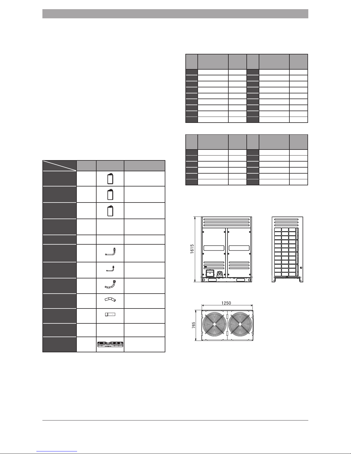
3. ACCESSORIES
Table.3-1
Model
Name
All of units Outline Function
Outdoor unit
installation manual
1
___________
Outdoor unit owner’s
manual
1
Upon completion leave
with customer
Indoor unit owner’s
manual
1
On completion leave with
customer
90° elbow
1 (8HP, 10HP)
2 (12HP~
16HP)
________ For connecting pipes
Seal plug 8 ________ For pipe cleaning
Connective pipe
accessory
1
(used in 8HP~16HP)
Connect to the high-pressrue
gas balance side
Connective pipe
accessory
1
(used in 8HP~16HP)
Connect to the liquid
pipe side
Connective pipe
accessory
1
(used in 8HP, 10HP, 12HP)
Connect to the highpressure gas pipe side
Connective pipe
accessory
1
(used in 14HP, 16HP)
Connect to the highpressure gas pipe side
Connective pipe
accessory
2
(used in 12HP)
Connect to the low-pressure
gas pipe or liquid pipe side
Screw bag 1 ________ Stored for service
Cable clip kit
1
(Optional)
For cable fastening
4. OUTDOOR UNIT INSTALLATION
4.1 Outdoor unit combination
Table.4-1
HP Mode
Max Qty.
of indoor
unit
HP Mode
Max Qty.
of indoor
unit
8 8HP×1 13 26 10HP+16HP 43
10 10HP×1 16 28 14HP×2 46
12 12HP×1 20 30 14HP+16HP 50
14 14HP×1 23 32 16HP+16HP 53
16 16HP×1 26 34 10HP×2+14HP 56
18 8HP+10HP 29 36 10HP×2+16HP 59
20 10HP+10HP 33 38
10HP+12HP+16HP
63
22 10HP+12HP 36 40
10HP+14HP+16HP
64
24 10HP+14HP 39 42 14HP×3 64
Table.4-2
HP Mode
Max Qty.
of indoor
unit
HP Mode
Max Qty.
of indoor
unit
44 14HP×2+16HP 64 56
10HP+14HP+16HP×2
64
46 14HP+16HP×2 64 58 14HP×3+16HP 64
48 16HP×3 64 60 14HP×2+16HP×2 64
50
8HP+10HP+16HP×2
64 62 14HP+16HP×3 64
52
10HP×2+16HP×2
64 64 16HP×4 64
54
10HP+12HP+16HP×2
64
4.2 Dimensions of outdoor unit
4.3 Selecting installation location
■ Ensure that the outdoor unit is installed in a well-ventilated location.
■ Ensure that the noise and exhaust ventilation of the outdoor
unit does not affect the neighbours of the property owner or its
surroundings.
■ Where possible ensure the shortest pipe route.
■ Ensure that the outdoor unit is installed in a cool location without
direct sunshine exposure or direct radiation.
Fig. 4-1
Unit: mm
6 720 862 437 (2016/10)
RDCI Series – All DC Inverter Outdoor Units
4 | OUTDOOR UNIT INSTALLATION
■ Do not install the outdoor unit in a dirty or severely polluted location,
to avoid blockages in the heat exchanger of the outdoor unit.
■ Do not install the outdoor unit in a location with oil pollution, high
salt content air or high content of harmful gases such as sulfurous
gas.
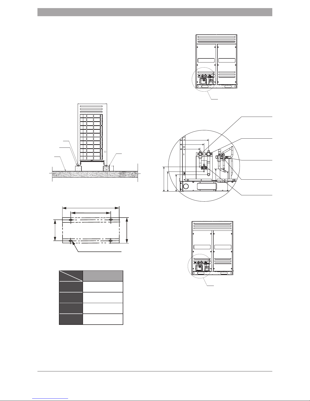
4.4 Base for outdoor unit
■ Base types
• Steel structure base
• Ensure you consult a construction engineer before installation.
Ensure the base has been installed to the correct dimensions set out
in this manual. Raise the unit at least 200mm from the floor.
■ Position illustration of screw bolt (Unit: mm)
Table.4-3 Unit: mm
HP
SIZE
8~16
A 1120
B 1250
C 736
D 765
■ Centering position illustration for each connective pipe (Unit: mm)
1) 8HP, 10HP
2) 12HP
Ø10 Expansion bolt
Rubber shocking
proof mat
Concrete base
h=200mm
Solid ground or
roofing
200 mm
Fig. 4-2
B
A
C
D
15×23long U-shape hole
Fig. 4-3
R
Fig. 4-4
250
205
245
290
230
205
200
170
Fig. 4-5
High-pressure
gas balance valve
Low-pressure gas
side of shut-off valve
High-pr
essure gas
side of shut-off valve
L
iquid side of
shut-off valve
Oil balance valve
R amplification
The connective pipe
diameter Ø19.1
The connective pipe
diameter Ø22.2
The connective pipe
diameter Ø19.1
The connective pipe
diameter Ø12.7
For the Cascaded Units
R
Fig. 4-6
RDCI Series – All DC Inverter Outdoor Units
6 720 862 437 (2016/10)
OUTDOOR UNIT INSTALLATION | 5
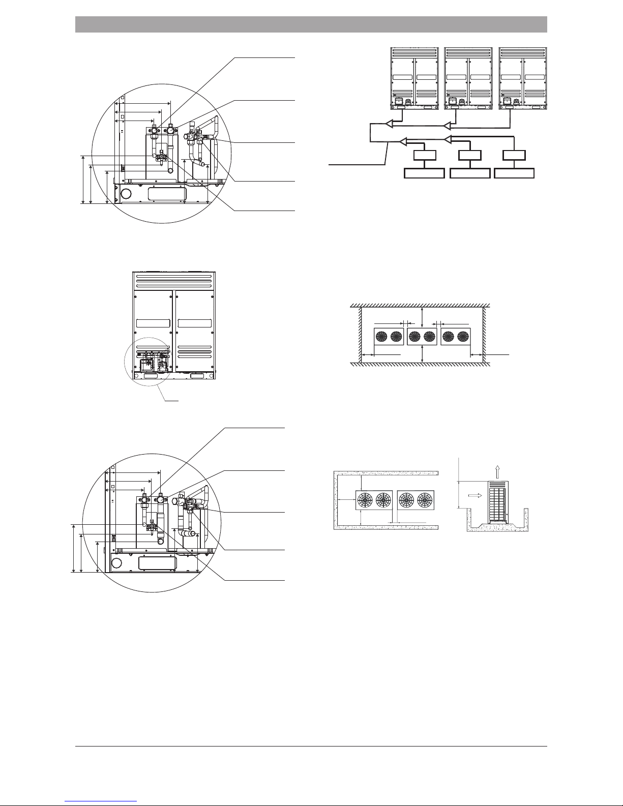
3) 14HP, 16HP
4.5 Outdoor Unit Cascade Sequence
A system with one or more outdoor units installed, will need to follow this
method: Outdoor units should be placed from large capacity to small
capacity. The largest should be installed nearest to the first branch joint. You
need to set the largest capacity as the master unit.
1) Place the 16HP at a side of the first branch joint site.
2) Place the unit from the large capacity to the small (See the detail
placement illustration)
3) Set 16HP as the main unit, while the 12HP and the 10HP as the slave
unit.
4.6 Installation space for outdoor unit
■ When installing the unit, leave a space for maintenance shown in
Fig.4-12 Install the power supply at the side of the outdoor unit. For
correct installation procedure, read installation manual.
■ In case there are obstacles surrounding the unit, refer to 4-17.
4.7 Layout
■ When the outdoor unit is higher than the surrounding obstacle
• One row
250
205
245
290
230
205
200
170
Fig. 4-7
High-pressure
gas balance valve
L
ow-pressure gas
side shut-off valve
High-pr
essure gas
side shut-off valve
L
iquid side
shut-off valve
Oil balance valve
R amplification
The connective pipe
diameter Ø19.1
The connective pipe
diameter Ø25.4
The connective pipe
diameter Ø19.1
The connective pipe
diameter Ø15.9
For the Cascaded Units
R
Fig. 4-8
250
205
245
290
230
205
200
165
Fig. 4-9
High-pressure
gas balance valve
L
ow-pressure gas
side shut-off valve
High-pr
essure gas
side shut-off valve
L
iquid side
shut-off valve
Oil balance v
alve
R amplification
The connective pipe
diameter Ø19.1
The connective pipe
diameter Ø28.6
The connectiv
e pipe
diameter Ø22.2
The connective pipe
diameter Ø15.9
F
or the Cascaded Units
Fig. 4-10
Outdoor unit
(38HP)
16HP
The 1st branch joint
12HP 10HP
SBOX SBOX SBOX
Indoor unit A Indoor unit B Indoor unit C
Fig. 4-12
100mm~500mm 100mm~500mm
>1000mm
>1000mm
>1000mm
>1000mm
Top view of the outdoor unit
Fig. 4-13
Front
100-500mm
Front
>1m
>1m>1m
>800mm

6 720 862 437 (2016/10)
RDCI Series – All DC Inverter Outdoor Units
6 | OUTDOOR UNIT INSTALLATION
• Two rows
• More than two rows
■ If the minimum clearance of 800mm above the unit can not be met,
see the figure below.
■ Ensure the surroundings are no more than 800mm high. If this is not
possible install mechanic exhaust device.
4.8 Set the snow-proof facility
■ In snowy areas, precautions should be taken to avoid unit failure or
lack of performance.
4.9 Explanation of valve
Table.4-4
Low-pressure gas pipe
Oil balance pipe
High-pressure gas balance pipe
Liquid pipe
High-pressure gas pipe
■ Installation illustration
Fig. 4-14
Front
100-500mm
Front
Front Front
>1m
>1m
>1m
>1m
>800mm
Fig. 4-15
Front
100-500mm
Front Front
Front Front
Front
>1m
>1m
>800mm
>1m>1m>1m
Fig. 4-16
Front
100-500mm
Front
>1m
>1m>1m
A
B
C
D
B
A
B
A
C
D
B
A
Fig. 4-17
Front view
Front view
Side view
Front view
>45° >300mm
>1000mm Airflow deflector
1
2
3
4
5
Fig. 4-19
Notes: 16HP as an example
1210
C
A
725
B
001
Fig. 4-20
Fig. 4-21
Example A
Support
Radius
Air outlet louver dimension (optional)
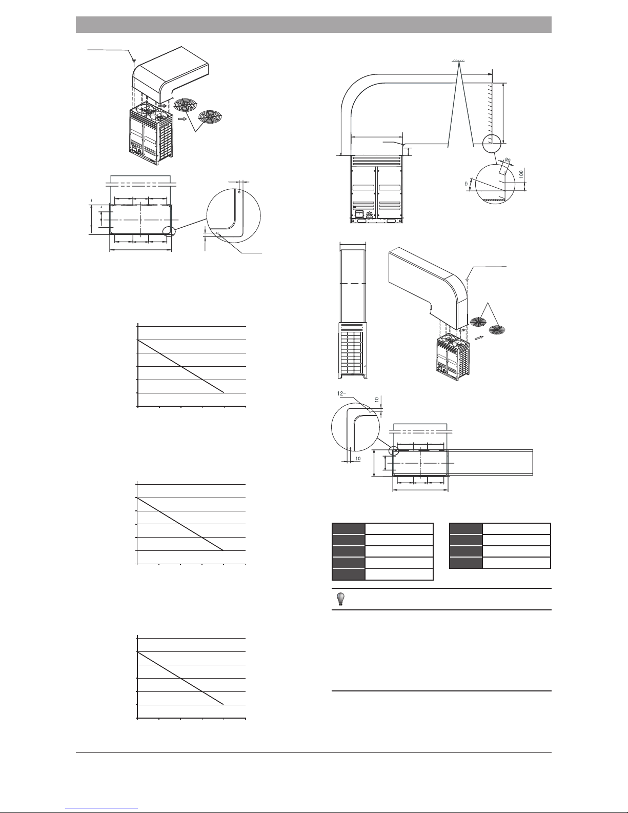
RDCI Series – All DC Inverter Outdoor Units
6 720 862 437 (2016/10)
OUTDOOR UNIT INSTALLATION | 7
■ Curve diagram of static pressure, air flow volume.
Table.4-5 Unit: mm Table.4-6 Unit: mm
A A≥300 A A≥300
B B≥250 B B≥250
C C≤3000 C C≤3000
D 750≤D≤760
θ
θ≤15°
θ
θ≤15°
NOTE
■ Before installing the air deflector, please ensure the fan grill has
been taken off.
■ Once air deflector has been installed, the air volume, cooling/
heating capacity will decrease. The maximum angle allowed for the
shutter is 15 degrees.
■ Only one bend set is allowed.
■ Install anti vibration pads in between the unit and air deflector.
Fig. 4-22
12 ST3.9 self-threading screws
Remove the fan grills
10
01
12-Ø3.2
393
567
1250
411 411213
411 411213
Fig. 4-23
9500
10000
10500
11000
11500
12000
12500
0 5 10 15 20 25
Fig. 4-24
8/10HP
Air pressure curve diagram
(Remove the fan grills)
Air volume (m
3
/h)
Static pressure (Pa)
10500
11000
11500
12000
12500
13000
13500
0 5 10 15 20 25
Fig. 4-25
12HP
Air pressure curve diagram
(Remove the fan grills)
Air volume (m
3
/h)
Static pressure (Pa)
12500
13000
13500
14000
14500
15000
15500
0 5 10 15 20 25
Fig. 4-26
14/16HP
Air pressure curve diagram
(Remove the fan grills)
Air volume (m
3
/h)
Static pressure (Pa)
B
0921
C
1210
A
Fig. 4-27
Example B
Support
Radius
Air outlet louver dimension (optional)
725
Ø3.2
393
567
1250
411 411
213
411 411213
Fig. 4-28
Fig. 4-29
12 ST3.9 self-threading screws
Remove the fan grills
6 720 862 437 (2016/10)
RDCI Series – All DC Inverter Outdoor Units
8 | REFRIGERANT PIPE
5. REFRIGERANT PIPE
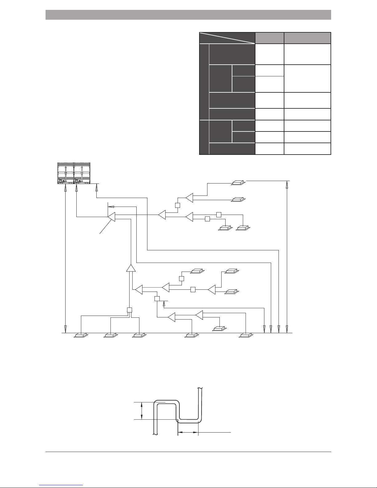
5.1 Length and drop height permitted
for the refrigerant pipework
Note: Ensure a distance of at least 0.5m between branch pipes.
Table.5-1
Permitted
value
Pipework
Pipe length
Total pipe length (Actual)
1000m
(Please refer to
the caution 5 of
conditions 2)
L1+(L2+L3+L4+L5+L6+L7
+L8+L9+L10+L11+L12+
L13)×2+a+b+c+d+e+f+g+
h+i+j+k+l+m+n
Maximum
pipework (L)
Actual
length
175m
L1+L7+L9+L11+j+k+n
Equivalent
length
200m
(Please refer to
caution 1)
Pipework (furthest from
the first line pipe branch)
equivalent length
40m/90m
(Please refer to
caution 5)
L7+L9+L11+j+k+n
SBOX to indoor unit
equivalent length
40m j+k+n
Drop height
Indoor unit
to outdoor
unit drop
height
outdoor
unit up
70m*
(Please refer
to caution 3)
outdoor unit
down
110m
(Please refer
to caution 4)
Indoor unit to indoor unit
drop height
30m _____________
N3
(140)
N5
(140)
N6
(71)
N7
(71)
N9
(56)
N8
(28)
N2
(71)
N4
(28)
N1
(71)
N10
(56)
A
B
C
E
F
Ⅱ
Ⅳ
Ⅲ
Ⅰ
b
c
d
f
g
j
h
i
l
k
m n
e
L
1
L2
L9
L13
L11
L10
L12
L3
a
SB1
SB2
SB3
SB4
SB5
SB6
L4
L5
L6
D
N11
(140)
p
N12
(140)
q
N13
(56)
r
L
8
L7
SB7
Fig. 5-1
Indoor unit
The first line branch pipe
Maximum height between outdoor and indoor units
unit and outdoor unit H≤110m
Maximum height from indoor unit to indoor unit.
drop height H≤30m
Outdoor unit
(one or more outdoor units)
Max pipework equivalent length L≤200m
(From the first line branch pipe) Maximum
pipework equivalent length L≤40m/90m
SBOX to indoor unit equivalent length L≤40m
* A system with a height difference above 70m is not supported as standard but is available on request for customisation.
Fig. 5-2
≥300m
≥300m

RDCI Series – All DC Inverter Outdoor Units
6 720 862 437 (2016/10)
REFRIGERANT PIPE | 9
CAUTION
1. The length between the branch pipes should be a minimum of 0.5m.
2. When the outdoor unit is installed above the indoor units and the distance
is greater than 20m, you must install oil return taps every 10m. Refer to
5-2.
3. When the outdoor unit is installed below the internal units and the length
exceeds 40m, the liquid pipe needs to be increased one size.
4. When the outdoor unit is installed below the internal units, the first
branch joint connection should be shorter than 40m. However when
certain conditions are met, the length can increase up to 90m.
Conditions
1. For all pipe sizing and limitations please follow the conditions below.
Conditions
■ L7+L9+L11+j+k+n≤90m L2~L13
Increasing the pipe diameter of the distribution pipe
■ To increase the pipe size, see below
Ø9.5 → Ø12.7 Ø12.7 → Ø15.9 Ø15.9 → Ø19.1
Ø19.1 → Ø22.2 Ø22.2 → Ø25.4 Ø25.4 → Ø28.6
Ø28.6 → Ø31.8 Ø31.8 → Ø38.1 Ø38.1 → Ø41.3
Ø41.3 → Ø44.5 Ø44.5 → Ø54.0
5.2 Select the refrigerant pipework type
Conditions
2. When calculating actual length of pipe, follow the example below.
L1+(L2+L3+L4+L5+L6+L7+L8+L9+L10+L11+L12+L13)
x2+a+b+c +d+e+f+g+h+i+j+k+l+m+n<1000m
Examples
Reference Figure. 5-1
Conditions
3. The length from the indoor unit to the nearest branch joint assembly
or SBOX ≤40m;
b, c, d, e, f, h, i, l, m, n, p, q, r ≤40m(Pipe diameter requirements, please
refers to table.5-8).
Examples
Reference Figure. 5-1
Conditions
4. The distance between [the outdoor unit to the furthest indoor unit]
and [the outdoor unit to the nearest indoor unit] is ≤40m.
The furthest indoor unit N10
The nearest indoor unit N11
(L1+L7+L9+L11 +j+k+n)-(L1 +L7+L8+p) <40m
Examples
Reference Figure. 5-1
L1
M
L
g1
j j j j j j
g2 g3
G1
N3
(140)
N5
(140)
N6
(71)
N7
(71)
N9
(56)
N8
(28)
N2
(71)
N4
(28)
N1
(71)
N10
(56)
A
B
C
E
F
Ⅱ
Ⅳ
Ⅲ
Ⅰ
b
c
d
f
g
j
h
i
l
N11
(140)
p
N12
(140)
q
N13
(56)
r
k
m n
e
L
2
L9L8
L7
L13
L11
L10
L12
L3
a
SB1
SB2
SB3
SB4
SB5
SB6
L4
L5
L6
D
SB7
W3
(10)W2(12)W1(16)
Fig. 5-3

6 720 862 437 (2016/10)
RDCI Series – All DC Inverter Outdoor Units
10 | REFRIGERANT PIPE
Table.5-2
Pipe name
Code (As per
the Fig. 5-2)
Main pipe L1
Indoor unit main pipe L2~L13
Indoor unit aux. pipe a, b, ...r
Indoor unit main pipe branching pipe assembly A, B, C, D, E
Indoor unit aux. pipe branching pipe assembly I, II, III, IV
Outdoor unit branching pipe assembly L, M
Outdoor unit connective pipe g1, g2, g3, G1
SBOX equipment SB1, ...SB7
5.3 Size of joint pipes for indoor unit
Table.5-3 Size of joint pipes for R410A indoor unit
Capacity of
indoor unit A
(×100W)
Indoor unit main pipe (inches)
Low-pressure
gas side
High-pressure
gas side
Liquid
side
Available
branching pipe
A<56 Ø12.7 Ø9.5 Ø6.4 IDU-BJR01
56≤A<166 Ø19.1 Ø15.9 Ø9.5 IDU-BJR01
166≤A<230 Ø22.2 Ø19.1 Ø9.5 IDU-BJR02
230≤A<330 Ø22.2 Ø19.1 Ø12.7 IDU-BJR02
330≤A<460 Ø28.6 Ø22.2 Ø12.7 IDU-BJR03
460≤A<660 Ø28.6 Ø22.2 Ø15.9 IDU-BJR03
660≤A<920 Ø34.9 Ø28.6 Ø19.1 IDU-BJR04
920≤A<1350 Ø41.3 Ø34.9 Ø19.1 IDU-BJR05
1350≤A Ø44.5 Ø38.1 Ø22.2 IDU-BJR05
e.x.1: Refer to Fig.5-2, the capacity of downstream units to L2 is
71×2+140+28=310, i.e. low pressure gas pipe for L2 is Ø22.2, high
pressure gas pipe is Ø19.1, high pressure liquid pipe is Ø12.7.
5.4 Size of joint pipes for outdoor unit
Based on the following tables, select the diameters of outdoor unit main
connective pipe. When the main pipe accessory is larger on the indoor unit,
use the larger pipe accessory.
Table.5-4 Size of joint pipes for R410A outdoor unit
Model
When the equivalent length of all liquid
pipes < 90m, the size of main pipe (inches)
Low-pressure
gas side
High-pressure
gas side
Liquid
side
The 1st
branching pipe for
indoor unit
8HP Ø22.2 Ø19.1 Ø9.5
IDU-BJR02
10HP Ø22.2 Ø19.1 Ø12.7
IDU-BJR02
12HP Ø25.4 Ø19.1 Ø12.7
IDU-BJR03
14~16HP Ø28.6 Ø22.2 Ø15.9
IDU-BJR03
18~22HP Ø31.8 Ø28.6 Ø15.9
IDU-BJR03
24HP Ø34.9 Ø28.6 Ø15.9
IDU-BJR04
26~32HP Ø34.9 Ø28.6 Ø19.1
IDU-BJR04
34~48HP Ø41.3 Ø34.9 Ø19.1
IDU-BJR05
50~64HP Ø44.5 Ø38.1 Ø22.2
IDU-BJR05
Table.5-5 Size of joint pipes for outdoor unit (R410a)
Model
When the equivalent length of all liquid
pipes ≥ 90m, the size of main pipe (inches)
Low-pressure
gas side
High-pressure
gas side
Liquid
side
The 1st
branching pipe for
indoor unit
8HP Ø22.2 Ø19.1 Ø12.7
IDU-BJR02
10HP Ø22.2 Ø19.1 Ø12.7
IDU-BJR02
12HP Ø25.4 Ø19.1 Ø15.9
IDU-BJR03
14~16HP Ø28.6 Ø22.2 Ø15.9
IDU-BJR03
18~22HP Ø31.8 Ø28.6 Ø19.1
IDU-BJR03
24HP Ø34.9 Ø28.6 Ø19.1
IDU-BJR04
26~32HP Ø34.9 Ø28.6 Ø22.2
IDU-BJR04
34~48HP Ø41.3 Ø34.9 Ø22.2
IDU-BJR05
50~64HP Ø44.5 Ø38.1 Ø25.4
IDU-BJR05
5.5 Branch pipes for outdoor unit
Table.5-6
Model
Outdoor unit pipe connective opening dimension (inches)
Low-pressure gas
side
High-pressure gas
side
Liquid side
8~12HP Ø22.2 Ø19.1 Ø12.7
14, 16HP Ø28.6 Ø22.2 Ø15.9
5.6 Multi pipe connection assembly and pipe
diameter for outdoor unit
Based on Table 5-7 select the branch pipe assembly for the outdoor unit.
Before installation, please read the Outdoor Unit Branching Pipe Installation
Manual carefully.
Table.5 -7 Outdoor unit branch pipe assembly (Illustration)
Outdoor
unit Qty.
Illustration
Outdoor unit
connective pipe
diameter
Parallel connect with
the branching pipes
2 units
L
g1g2
g1, g2:
8~12HP:
Ø22.2/Ø19.1/Ø12.7
14, 16HP:
Ø28.6/Ø22.2/Ø15.9
L:
ODU-BJR02
3 units
L
M
g1g2
G1
g3
g1, g2, g3:
8~12HP:
Ø22.2/Ø19.1/Ø12.7
14, 16HP:
Ø28.6/Ø22.2/Ø15.9
G1: Ø34.9/Ø28.6/
Ø19.1
L+M:
ODU-BJR03
4 units
L
M
N
g1g2
G1 G2
g3g4
g1, g2, g3, g4:
8~12HP:
Ø28.2/Ø19.1/Ø12.7
14, 16HP:
Ø28.6/Ø22.2/Ø15.9
G1: Ø34.9/Ø28.6/Ø19.1
G2: Ø41.3/Ø34.9/Ø22.2
L+M+N:
ODU-BJR04
5.7 Example
1) Take (10+12+16) HP for the three modules as an example to clarify the
pipe selection.
2) Take Fig.5-2 as an example, providing that the equivalent length of all
pipes in this system is larger than 90m.
Table.5-8
Capacity
of indoor unit A
(×100W)
Indoor unit aux. pipe (between branch joint and branch
joint/SB) (inches)
The branch pipe
assembly of indoor
unit aux. pipe
Gas side Liquid side
A<160 Ø15.9 Ø9.5 IDU-BJR01
Capacity
of indoor unit A
(×100W)
Indoor unit aux. pipe (between indoor unit and branch joint/SB) (inches)
When branching
pipe’s length ≤10m
When branching pipe’s length>10m
Gas side Liquid side Gas side Liquid side
A<56 Ø12.7 Ø6.4 Ø15.9 Ø9.5
160≥A≥56 Ø15.9 Ø9.5 Ø19.1 Ø12.7
Main pipe
Main pipe
Main pipe
RDCI Series – All DC Inverter Outdoor Units
6 720 862 437 (2016/10)
REFRIGERANT PIPE | 11
A Branching pipe at the inside of the unit.
There are b, c, d, e, f, h, i, l, m, n, p, q, r branching pipes at the inside
of the unit, the branching pipe diameter should be select as per Table
5-8.
B Main pipe and aux. pipe at the inside of the unit (Refer to Table 5-3
and Table 5-8)
1) The aux. pipe a with N1, N2 downstream indoor units that total
capacity is 71×2=142, the pipe a diameter is Ø15.9/Ø9.5, thus
select IDU-BJR01 for the branching pipe I.
2) The main pipe L3 with N1, N2 downstream indoor units that total
capacity is 71×2=142, the pipe L3 diameter is Ø19.1/Ø15.9/Ø9.5,
thus select SBOX02-1 for SB1.
3) The main pipe L5 with N3 downstream indoor units that total capacity
is 140, the pipe L5 diameter is Ø19.1/Ø15.9/Ø9.5, thus select
SBOX02-1 for SB2.
4) The main pipe L6 with N4 downstream indoor units that total capacity
is 28, the pipe L6 diameter is Ø12.7/Ø9.5/Ø6.4, thus select
SBOX02-1 for SB3.
5) The main pipe L4 with N3, N4 downstream indoor units that total
capacity is 140+28=168, the pipe L4 diameter is Ø22.2/Ø19.1/
Ø9.5, thus select IDU-BJR02 for the branching pipe C.
6) The main pipe L2 with N1~N4 downstream indoor units that total
capacity is 71×2+140+28=310, the pipe L2 diameter is Ø22.2/
Ø19.1/Ø12.7, thus select IDU-BJR02 for the branching pipe B.
7) The main pipe L12 with N5 downstream indoor units that total
capacity is 140, the pipe L12 diameter is Ø19.1/Ø15.9/Ø9.5, thus
select SBOX02-1 for SB4.
8) The aux. pipe g with N6, N7 downstream indoor units that total
capacity is 71×2=142, the pipe g diameter is Ø15.9/Ø9.5, thus
select IDU-BJR01 for the branching pipe II.
9) The main pipe L13 with N6, N7 downstream indoor units that total
capacity is 71×2=142, the pipe L13 diameter is Ø19.1/Ø15.9/
Ø9.5, thus select SBOX02-1 for SB5.
10) The main pipe L10 with N5~N7 downstream indoor units that total
capacity is 140+71×2=282, the pipe L10 diameter is Ø22.2/
Ø19.1/Ø12.7, thus select IDU-BJR02 for the branching pipe F.
11) The aux. pipe k with N9, N10 downstream indoor units that total
capacity is 56×2=112, the pipe k diameter is Ø15.9/Ø9.5, thus
select IDU-BJR01 for the branching pipe III.
12) The aux. pipe j with N8~N10 downstream indoor units
that total capacity is 28+56×2=140, the pipe j diameter
is Ø15.9/Ø9.5, thus select IDU-BJR01 for the branching
pipe IV.
13) The main pipe L11 with N8~N10 downstream indoor units that total
capacity is 28+56×2=140, the pipe L11 diameter is Ø19.1/Ø15.9/
Ø9.5, thus select SBOX02-1 for SB6.
14) The main pipe L9 with N5~N10 downstream indoor units that total
capacity is 140+56×2+71×2+28=422, the pipe L9 diameter is
Ø28.6/Ø22.2/Ø12.7, thus select IDU-BJR03 for the branching pipe
E.
15) The main pipe L8 with N11~N13 downstream indoor units that total
capacity is 140×2+56=336, the pipe L8 diameter is Ø28.6/Ø22.2/
Ø12.7, thus select SBOX04-1 for SB7.
16) The main pipe L7 with N5~N13 downstream indoor units that total
capacity is 140×3+71×2+56×3+28=758, the pipe L7 diameter is
Ø34.9/Ø28.6/Ø19.1, thus select IDU-BJR04 for the branching pipe
D.
17) The main pipe L1 with N1~N10 downstream indoor units that total
capacity is 140×4+71×4+56×3+28×2=1064, thus select IDUBJR05 for the branching pipe A.
C Main pipe (Refer to Table 5-3, Table 5-5):
Main pipe L1 in the Fig.5-2, which upstream outdoor units
total capacity is 16+12+10=38, base on table 5-5, the low
pressure gas/high pressure gas/liquid pipe diameter are Ø41.3/
Ø34.9/Ø22.2, total capacity of the downstream indoor unit is
140×4+71×4+56×3+28×2=1064, base on table 5-3, the low
pressure gas/high pressure gas/liquid pipe diameter are Ø41.3/
Ø34.9/Ø19.1, take the large one for your selection, final confirm the
main pipe diameter is: low pressure gas/high pressure gas/liquid pipe
Ø41.3/Ø34.9/Ø22.2.
D Parallel connect the outdoor units
1) The outdoor unit linked by Pipe g1 is 10HP, parallel connects with
outdoor unit. the connective pipe diameter to be selected according to
its connector size is Ø22.2/Ø19.1/Ø12.7;
The outdoor unit linked by Pipe g2 is 12HP, parallel connects with
outdoor unit. the connective pipe diameter to be selected according to
its connector size is Ø22.2/Ø19.1/Ø12.7;
The outdoor unit linked by Pipe g3 is 16HP, parallel connects with
outdoor unit. the connective pipe diameter to be selected according to
its connector size is Ø28.6/Ø22.2/Ø15.9.
2) G1 is the upstream of the two parallel connected outdoor units, refer
to Table 5-5 select the two parallel connected outdoor unit, the pipe
diameter is Ø34.9/Ø28.6/Ø19.1.
3) Parallel connect the three outdoor units, refer to Table 5-7 should
select ODU-BJR03 for outdoor unit connective pipes (L+M).
5.8 Caution for brazing
■ When brazing use nitrogen to pass through the pipework. This helps
stop oxidisation inside the refrigerant pipework.
■ Do not use anti-oxidants when brazing the pipe joints. Residue can
block pipes and cause damage to the equipment.
■ Do not use flux when brazing. Use phosphor copper brazing filler
alloy (BCuP) which does not require flux.
■ Flux is extremely harmful on refrigerant systems. This can cause
corrosion and deterioration of the refrigerant oil.
5.9 Removing the contaminants in the pipework
■ Ensure there is no dirt or water in the pipework before connecting.
■ Ensure you flush nitrogen through to clear the refrigerant pipe work.
This needs to be done before connecting to the outdoor unit.
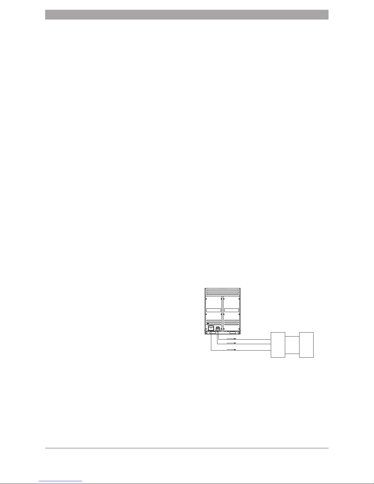
5.10 Strength/Tightness Test
Pressure test the system with nitrogen to 40kgf/cm2. Ensure a 24 hour
strength test has been completed for all new installations. For guidance on
tightness testing for existing installations, please refer to F Gas Regulations.
Fig. 5-4
SBOX Indoor unit
Liquid pipe
Nitrogen
Nitrogen
Nitrogen
High-pressure gas pipe
Low-pressure gas pipe
 Loading...