


D8125MUX
Installation and Operation Guide
Multiplex Bus
EN Interface

EN | 2 |
D8125MUX | Installation and Operation Guide | 1.0 |
|
|
Contents |
|
|
1.0 |
Introduction ............................................... |
3 |
1.1 |
Description...................................................... |
3 |
1.2 |
Listings............................................................ |
3 |
1.3 |
Specifications.................................................. |
3 |
2.0 |
Operation .................................................. |
4 |
3.0 |
Installation................................................. |
4 |
3.1 |
Installing the enclosure ................................... |
4 |
3.2 |
Wiring to the control panel ............................. |
5 |
3.2.1 |
Disconnecting the Battery and Transformer ... |
5 |
3.2.2 |
Wiring Procedure ............................................ |
5 |
4.0 |
Program Multiplex Bus Points .................... |
6 |
4.1 |
Connecting the D5060 Programmer ............... |
6 |
4.2 |
Programming................................................... |
8 |
4.2.1 |
Powering the D5060 ....................................... |
8 |
4.2.2 |
Programming Points........................................ |
8 |
4.2.3 |
Removing a Point from the D8125MUX........... |
8 |
4.2.4 |
Interrogation Mode ......................................... |
9 |
4.3 |
Wiring the D8125MUX to Multiplex Points...... |
9 |
4.4 |
Using Power B and MUX BUS B (Optional)... |
10 |
4.5Wiring Multiplex Devices to the Multiplex Bus
|
...................................................................... |
10 |
4.6 |
Installing a Multiplex Device ......................... |
11 |
4.6.1Adding Multiplex Devices to the Control Panel
...................................................................... 11
4.6.2Removing Multiplex Devices from the Control
|
Panel ............................................................. |
11 |
4.7 |
Point Matrix Tables ....................................... |
13 |
4.8 |
Single Input Multiplex Devices ...................... |
21 |
4.9MX250 Photoelectric Smoke Detectors and MXB2W Base or D7050 Photoelectric Smoke
|
Detector and D7050-B6 Base........................ |
21 |
4.10 |
DS7460(i) Dual Input Multiplex Module ....... |
22 |
4.11 |
DS7432 Eight Input Remote Module............. |
22 |
4.12 |
DS7465(i) Input/Output Module................... |
23 |
5.0 |
Testing the System................................... |
24 |
5.1 |
Local Walk Test (Command 44) .................... |
24 |
5.2 |
Missing Multiplex Points ............................... |
24 |
5.3 |
Extra Multiplex Points ................................... |
24 |
5.4Ground Fault Notification on Multiplex Devices
|
...................................................................... |
24 |
6.0 |
Troubleshooting ....................................... |
25 |
Figures |
|
|
Figure 1: |
D8125MUX Multiplex Bus Interface Module |
|
|
.................................................................. |
4 |
Figure 2: |
Installation diagram .................................. |
4 |
Figure 3: |
D8125MUX Wiring Diagram ...................... |
5 |
Figure 4: |
D5060 Multiplex Point Programmer.............. |
6 |
Figure 5: |
Installing Multiplex Points without DIP |
|
|
Switches Wiring Diagram.......................... |
7 |
Figure 6: |
Installing Multiplex Points with DIP |
|
|
Switches Wiring Diagram.......................... |
7 |
Figure 7: |
Programmer Cables (included) ................ |
7 |
Figure 8: |
Wiring the D8125MUX to Detection |
|
|
Systems Multiplex Points ......................... |
9 |
Figure 9: |
Wiring Multiplex Devices to MUX Bus..... |
10 |
Tables |
|
|
Table 1: |
Specifications ........................................... |
3 |
Table 2: |
Operation LED Descriptions..................... |
4 |
Table 3: |
D5060 LED Definitions ................................ |
6 |
Table 4: |
Point Type Entry Code.............................. |
8 |
Table 5: |
D8125MUX Line Length .......................... |
10 |
Table 6: |
Control Panel to D8125MUX Distance.... |
10 |
Table 7: |
Multiplex Devices.................................... |
11 |
Table 8: |
Point Conversion Table........................... |
12 |
Table 9: |
DS7457i, DS7461i, and DS7465i Switch |
|
|
Settings When Using D8125MUX on |
|
|
ZONEX 1 ................................................. |
14 |
Table 10: |
DS7457i, DS7461i, and DS7465i Switch |
|
|
Settings When Using D8125MUX on |
|
|
ZONEX 2 ................................................. |
17 |
Table 11: |
DS7460i Switch Settings When Using |
|
|
D8125MUX.............................................. |
19 |
Table 12: |
Single Input Multiplex Device Point |
|
|
Response Configuration ......................... |
21 |
Table 13: |
MX250, MX250TH, D7050, and D7050TH |
|
|
Point Type Configuration........................ |
21 |
Table 14: |
DS7460(i) Point Type Configuration ...... |
22 |
Table 15: |
DIP Switch Settings ................................ |
22 |
Table 16: |
DS7432 Point Type Configuration .......... |
23 |
Table 17: |
DS7465(i) Point Type Configuration ...... |
23 |
Table 18: |
Troubleshooting...................................... |
25 |
2 |
Bosch Security Systems, Inc. | 12/15 | F01U034973-03 |
D8125MUX | Installation and Operation Guide | 1.0 Introduction
1.0Introduction
1.1Description
Use the D8125MUX Multiplex Bus Interface Module to connect multiplex points to the ZONEX bus on the following Bosch Security Systems control panels: new G Series (B9512G, B9512G-E, B8512G, B8512G-E),
G Series (D9412GV4, D7412GV4, D7212GV4, D9412GV3, D7412GV3, D7212GV3, D9412GV2, D7412GV2, D7212GV2, D9412G, D7412G, D7212G), D9412, D7412, D7212, D9112, and D9124 with version 5.22 or greater firmware. Install the D8125MUX on ZONEX 1 and ZONEX 2 (G Series, D9412, and D9112 only). The multiplex bus interface supports two independent multiplex buses; therefore, a fault on one multiplex bus does not prevent the other from operating normally.
The D8125MUX scans the multiplex points connected to it and reports the point status to the control panel.
Also available on the D8125MUX are auxiliary power terminals labeled Power A (+,-), Power B (+,-) that support remote devices requiring an uninterrupted source of power.
The B600 Retrofit (ZONEX) module is required to use the D8125MUX on the B9512G, B9512G-E, B8512G, and B8512G-E control panels.
See the Control Panel Approved Applications Compliance Guide or the Installation and System Reference Guide to determine the required equipment and enclosures for the application.
1.2Listings
The D8125MUX is UL Listed as a subassembly in the following categories:
US
UL 864 |
Control Units, System |
||
|
|
|
(UOJZ) |
|
|
|
|
UL1023 |
Household Burglar Alarm |
||
|
|
|
Systems (NBSX) |
UL1610 |
Central Station Alarm |
||
|
|
|
Units (AMCX) |
UL609 |
Local Alarm Units (AOTX) |
||
UL365 |
Police Station Connect |
||
|
|
|
Alarm Units (APAW) |
UL1076 |
Proprietary Alarm Units |
||
|
|
|
(APOU) |
UL 985 |
Household Fire Warning |
||
|
|
|
System Units |
CA |
|
||
|
|
|
|
ULC S303 |
Local Burglar Alarm Units |
||
|
|
|
and Systems |
ULC/ORD-C1076 |
Proprietary Burglar Alarm |
||
|
|
|
Units and Systems |
ULC/ORD-C1023 |
Household Burglar Alarm |
||
|
|
|
System Units |
|
|
|
|
|
|
|
|
The D7212GV2 and D7212G are not UL Listed for UL 864 commercial fire applications.
1.3Specifications
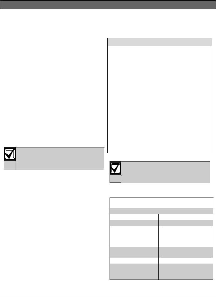
Table 1: Specifications
Operating Voltage
Current Requirements
Maximum Current Draw (using both MUX bus outputs and both power outputs)
Operating Temperature
Relative Humidity
Dimensions (H x W x
D)
Nominal 12 VDC
D8125MUX only: 140 mA
678 mA
+32°F to +120°F (0°C to +49°C)
0 to 93%
1.0 in. x 3.25 in. x 5.5 in.
(25 mm x 8.3 cm x 14.0 cm)
Bosch Security Systems, Inc. | 12/15 | F01U034973-03 |
3 |
D8125MUX | Installation and Operation Guide | 2.0 Operation
2.0 Operation
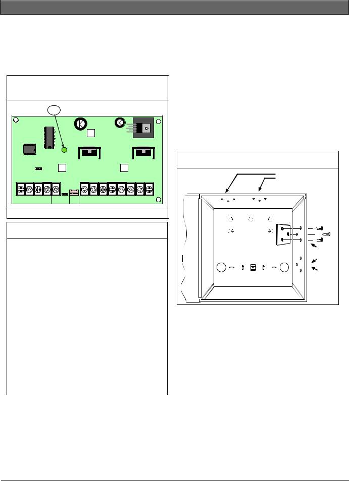
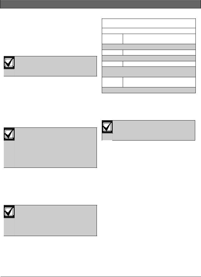
The D8125MUX indicates its status using the green Operation LED (Figure 1). Refer to Table 2 for a description of the Operation LED.
Figure 1: D8125MUX Multiplex Bus Interface
Module
1
|
|
RESET |
|
|
|
|
|
|
|
|
|
|
|
12V |
IN |
OUT |
GND |
FIRE MANUAL PROG |
+ |
- |
+ |
- |
+ |
- |
+ |
- |
|
|
ZONEX BUS |
|
WALK TEST |
PORT |
POWER A |
MUX BUS A |
|
POWER B |
MUX BUS B |
||||
1 - Operation LED
Table 2: Operation LED Descriptions
|
|
LED Status |
Meaning |
|
|
Flashing 1/2 |
Indicates normal operation. |
second on, 1/2 |
|
second off |
|
Off |
A module fault is indicated. |
|
Refer to Section 6.0 |
|
Troubleshooting on page 25. |
|
|
On |
The Multiplex Point |
|
Programmer is connected to |
|
the D8125MUX. |
Double flash |
Reset the D8125MUX EEPROM |
|
with the reset pin by plugging |
|
in the D5060 Programmer and |
|
placing the shorting bar over |
|
the reset pin. The LED rapidly |
|
flashes twice followed by a |
|
pause. |
3.0 Installation
The D8125MUX is installed in the control panel enclosure and is connected to either ZONEX 1 or ZONEX 2 on the control panel or the B600 Retrofit (ZONEX) module.
3.1Installing the enclosure
Follow the procedure below to install the D8125MUX in the enclosure with the control panel or B600.
1.Align the D8125MUX module with any of the four mounting locations in the enclosure. See Figure 2.
2.Use the screws provided with the module to secure it in the enclosure.
Figure 2: Installation diagram
Horizontal Mounting |
Locations |
Vertical |
Mounting |
Locations |
(Reserved |
Dual Phon |
Switcher M |
4 |
Bosch Security Systems, Inc. | 12/15 | F01U034973-03 |
D8125MUX | Installation and Operation Guide | 3.0 Installation
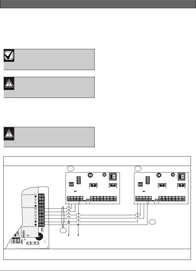
3.2Wiring to the control panel
Follow the procedure below to wire one or two D8125MUX modules to the 9000 Series, and G Series control panels. For the B9512G, B9512G-E, B8512G, B8512G-E control panels, see the Control Panels Installation and System Reference Guide.
The B600 Retrofit (ZONEX) module is required to use the D8125MUX on the B9512G, B9512G-E, B8512G, and B8512G-E control panels.
Remove all power (AC and Battery) before making any connections. Failure to do so may result in personal injury and/or equipment damage.
3.2.1Disconnecting the Battery and Transformer
1.Disconnect the battery by unhooking the positive (red) battery lead from the battery.
2.Unplug the transformer.
Reversed polarity damages the D8125MUX. Make sure you wire the D8125MUX AUX and GND terminals to the control panel.
3.2.2Wiring Procedure
For Points 9 up to Point 127:
1.Connect the GND terminal of the D8125MUX to the control panel ZONEX COMMON terminal.
2.Connect the OUT terminal of the D8125MUX module to ZONEX IN 1.
3.Connect the IN terminal of the D8125MUX module to ZONEX OUT 1.
4.Connect the AUX terminal of the D8125MUX to ZONEX POWER + terminal.
For Points 129 up to Point 247:
1.Connect the GND terminal of the D8125MUX to the control panel ZONEX COMMON terminal.
2.Connect the OUT terminal of the D8125MUX module to ZONEX IN 2.
3.Connect the IN terminal of the D8125MUX module to ZONEX OUT 2.
4.Connect the AUX terminal of the D8125MUX to ZONEX POWER + terminal.
Do not connect more than one D8125MUX to ZONEX 1 (IN and OUT terminals) or ZONEX 2 (IN and OUT terminals).
Figure 3: D8125MUX Wiring Diagram
1 |
2 |
PERIPHERAL DEVICE CONNECTIONS |
|||
|
RED |
POWER + |
|
|
YELLOW |
DATA BUS A |
|
|
GREEN |
DATA BUS B |
|
|
BLACK |
COMMON |
|
|
N.F.P.A. |
ZONEX OUT 1 |
|
|
Style 3.5 |
|
|
|
Signaling |
|
|
|
Line |
ZONEX IN 1 |
|
|
Circuits |
|
|
|
|
ZONEX OUT 2 |
|
|
|
ZONEX IN 2 |
|
|
|
ZONEX POWER + |
|
|
|
ZONEX COMMON |
|
|
Detect |
Monitor Normal Ringing |
PROG |
|
Point 8 |
|
|
GND FAULT |
|
CONN |
|
E |
D |
Operation When When |
|
I |
|
||
N |
S |
GRN Pulses Flickers |
|
A |
L |
|
|
A |
|
|
|
B |
B |
|
|
L |
|
|
|
E |
E |
|
|
|
|
RESET |
|
|
|
|
|
|
|
|
|
|
|
12V |
IN |
OUT |
GND |
FIRE MANUAL PROG |
+ |
- |
+ |
- |
+ |
- |
+ |
- |
|
|
ZONEX BUS |
|
WALK TEST |
PORT |
POWER A |
MUX BUS A |
|
POWER B |
MUX BUS B |
||||
4
|
|
RESET |
|
|
|
|
|
|
|
|
|
|
|
12V |
IN |
OUT |
GND |
FIRE MANUAL PROG |
+ |
- |
+ |
- |
+ |
- |
+ |
- |
|
|
ZONEX BUS |
|
WALK TEST |
PORT |
POWER A |
MUX BUS A |
|
POWER B |
MUX BUS B |
||||
3
1 - |
D8125MUX on ZONEX 1 |
3 - |
ZONEX Common Terminal |
2 - |
D8125MUX on ZONEX 2 |
4 - |
Supervised, Power Limited. |
Bosch Security Systems, Inc. | 12/15 | F01U034973-03 |
5 |
D8125MUX | Installation and Operation Guide | 4.0 Program Multiplex Bus Points
4.0 Program Multiplex Bus
Points
Use the D5060 Programmer (Figure 4 and Table 3) to program multiplex bus points for the B9512G, B9512G-E, B8512G, B8512G-E, D9412GV4, D7412GV4, D7212GV4, D9412GV3, D7412GV3, D7212GV3, D9412GV2, D7412GV2, D7212GV2, D9412G, D7412G, D7212G, D9412, D7412, D7212, and D9112 control panels. In addition to programming points, the D5060 can also be used to program and read information from a D8125MUX.
The B600 Retrofit (ZONEX) module is required to use the D8125MUX on the B9512G, B9512G-E, B8512G, and B8512G-E control panels.
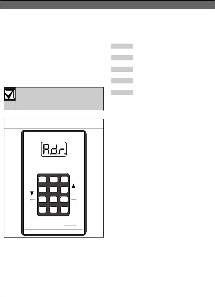
Figure 4: D5060 Multiplex Point Programmer
EXT. |
SERIAL PORT |
MUX |
POWER |
|
POINTS |
|
|
|
INTERROGATION MODE

ON
(HOLD)
YES |
1 |
2 |
3 |
NO |
|
|
|
||
DOWN 4 |
5 |
6 |
UP |
|
7 8 9
*0 #
CLEAR ENTER

 OFF
OFF 

(HOLD)

 INTERROGATE
(HOLD)
MULTIPLEX POINT PROGRAMMER
Table 3: |
D5060 LED Definitions |
|
|
|
|
|
|
|
Display |
|
Definition |
Adr |
|
Enter address. |
A.dr |
|
Enter address for Interrogation Mode. |
bAd |
|
Battery voltage is below 15 V. |
Err |
|
Point was not programmed correctly. |
Lob |
|
Battery voltage is below 16 V. |
noP |
|
No response from point. |
PnL |
|
Communications with the D8125 failed. |
rSP |
|
Point responds to address. |
tYP |
|
Enter point type. |
t.YP |
|
Enter point type for Interrogation Mode |
4.1Connecting the D5060
Programmer
1.When using external power, attach the flying leads of the included power cable to the output terminals of a 16.5 VAC transformer. Insert the plug end into the jack labeled EXT. POWER on the programmer. Refer to Figure 5, Figure 6, and
Figure 7.
2.Use the serial cable provided to connect the D8125MUX to the jack labeled SERIAL PORT on the programmer.
3.For multiplex devices without DIP switches, use the multiplex programmer cable provided to connect the point to be programmed to the port labeled MUX POINTS as shown in Figure 5. Use the appropriate connector, either the alligator clips or the probes, to connect the programmer to a point. For multiplex points with programmable DIP switches, program the point using the DIP switches. Connect the programmer to the D8125MUX as shown in Figure 6.
6 |
Bosch Security Systems, Inc. | 12/15 | F01U034973-03 |

D8125MUX | Installation and Operation Guide | 4.0 Program Multiplex Bus Points
Figure 5: Installing Multiplex Points without DIP Switches Wiring Diagram
3
1 |
2 |
|
+ |
- |
+ |
- |
+ |
- |
+ |
- |
EXT. |
SERIAL PORT |
MUX |
POWER |
|
POINTS |
INTERROGATION MODE |
|
|
|
4 |
|
1 - External power
2 - D8125MUX
3 - Multiplex point without DIP switches (non-i models)
4 - D5060 Multiplex Point Programmer
Figure 6: Installing Multiplex Points with DIP Switches Wiring Diagram
1 |
2 |
|
RESET |
12V |
IN |
OUT |
GND |
FIRE MANUAL PROG |
+ |
- |
+ |
- |
+ |
- |
+ |
- |
|
|
ZONEX BUS |
|
WALK TEST |
PORT |
POWER A |
MUX BUS A |
|
POWER B |
MUX BUS B |
||||
Figure 7: |
Programmer Cables (included) |
|
|
1 |
|
|
2 |
|
|
3 |
|
1 - |
C310 Serial Cable |
|
2 - C319 External Power Supply Cable |
||
3 - C320 Multiplex Programmer Cable |
||
EXT. |
SERIAL PORT |
MUX |
POWER |
|
POINTS |
|
|
|
INTERROGATION MODE 
3
1 - External power
2 - D8125MUX
3 - D5060 Multiplex Point Programmer
Bosch Security Systems, Inc. | 12/15 | F01U034973-03 |
7 |
D8125MUX | Installation and Operation Guide | 4.0 Program Multiplex Bus Points
4.2Programming
4.2.1Powering the D5060
Turn on the D5060 by pressing and holding the [1] key until the unit beeps. To turn the unit off, press and hold the [#] and [*] keys simultaneously until the unit beeps.
After 5 minutes of inactivity, the programmer powers down automatically to conserve power.
4.2.2Programming Points
1.The D5060 shows the prompt Adr after it is powered. This indicates that it is ready to begin programming.
2.If the multiplex device has no DIP switches, connect the D5060 to the point to be programmed as shown in Figure 5 on page 7. If the multiplex device has DIP switches, program the device using its DIP switches.
If the multiplex device has no DIP switches, connect the D8125MUX and the multiplex device to be programmed to the D5060 for simultaneous programming (Figure 5). If the multiplex device has DIP switches, program the device using its DIP switches, and program the D8125MUX using the D5060 (Figure 6 on page 7).
3.Enter the point’s three-digit address. The address must be between 1 and 255. Press [#].
The programmer shows tyP.
4.Enter the number corresponding to the point type you are programming as shown in Table 4 and press [#]. The programmer alternately shows the address and the point type.
When you program for a multiplex smoke device by entering decimal value 4 or 5 Table 4, an 18-second timer starts counting. Do not disconnect the multiplex smoke device until after the timer counts down to zero.
Table 4: Point Type Entry Code
|
|
Decimal |
Point Type |
Value |
|
0Remove point from D8125MUX
1Contact
2Sensor (or single point module)
3I/O module
4Multiplex smoke without low temperature
5Multiplex smoke with low temperature (0°C)
6Dual point
5.Press [#] to program a point connected to the D5060 and the D8125MUX (if connected), or press [1] to program the D8125MUX only. If the multiplex device has DIP switches, program the device using its DIP switches.
Press [*] at any time to return to a previous step in the procedure.
6.If the point is programmed correctly, the unit beeps once and shows Adr, indicating it is ready to program the next point. If the point was not programmed correctly, the unit sounds a threebeep error tone and one of the following messages appears:
Err: The point was not programmed correctly. PnL: Communications with the D8125MUX failed.
7.Press [*] to clear the entry, or press [#] to reprogram.
If programming the D8125MUX and multiplex device simultaneously and only one receives the program, the D5060 shows Adr. If having troubles with the point after installation, try programming the D8125MUX and multiplex devices separately.
4.2.3Removing a Point from the D8125MUX
1.Apply power to the D5060 and connect the programmer to the D8125MUX only.
2.Enter the address of the point you want to remove.
3.When prompted for a point type, press [0]. Refer to Table 4. Then press [#].
4.Press [1] to remove the point.
5.If the point is programmed correctly, the D5060 beeps once and Adr appears.
8 |
Bosch Security Systems, Inc. | 12/15 | F01U034973-03 |
D8125MUX | Installation and Operation Guide | 4.0 Program Multiplex Bus Points
4.2.4Interrogation Mode
You can also use the programmer to read information from the D8125MUX and multiplex points. Refer to Section 4.1 Connecting the D5060 Programmer on page 6 to install the D5060.
4.2.4.1 Reading Information from the D8125MUX
1.To enter Interrogation Mode, press and hold [7] and [9] simultaneously until the unit beeps.
2.The LED marked INTERROGATION MODE lights. A.dr appears prompting you to enter a starting address.
3.Enter an address followed by [#]. The Interrogation LED flashes.
4.Press [#] to read point information from the D8125MUX at that address.
5.Press [4] to read the previous address information from the D8125MUX.
6.Press [6] to read the next address information from the D8125MUX.
If communication between the unit and the D8125MUX fails, the unit sounds a three-beep error tone and shows PnL.
7.Exit Interrogation Mode by pressing and holding [*] until the unit beeps.
4.2.4.2 Reading Information from MUX Points
Disconnect all multiplex points from the D8125MUX and the multiplex bus before reading multiplex point information.
1.To enter Interrogation Mode, press and hold [7] and [9] simultaneously until the unit beeps. The LED marked INTERROGATION MODE lights.
2.The display reads A.dr prompting you to enter a starting address. Enter an address and press [#].
3.Press [1].
4.When t.YP appears at the keypad, enter the point type of the multiplex point as shown in Table 4 on page 8 and press [#].
5.If a point responds to the address, the programmer beeps once and rSP appears. If the point does not respond, the unit beeps three times and the display reads noP.
6.Exit Interrogation Mode by pressing and holding [*] until the unit beeps.
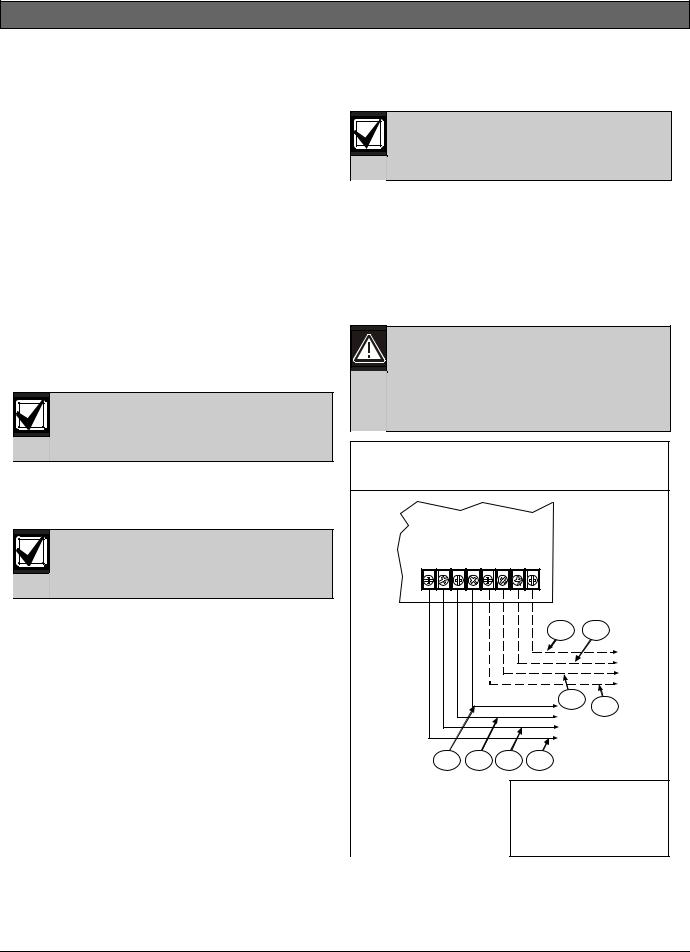
4.3Wiring the D8125MUX to Multiplex Points
Do not use shielded or twisted pair cable.
1.Connect Power A+ and Power A- on the D8125MUX to multiplex devices that require uninterrupted auxiliary power. Refer to Figure 8 on page 9. Up to 200 mA is available at these terminals.
2.Connect MUX BUS A+ and A- on the D8125MUX to the positive and negative bus wires of the multiplex points. The maximum allowable current on MUX BUS A is 75 mA.
3. |
Remove power from the D8125MUX before connecting or disconnecting multiplex devices. Connecting or disconnecting a multiplex device while the D8125MUX is powered could cause the multiplex device address setting to reprogram or scramble.
Figure 8: |
Wiring the D8125MUX to Detection |
||||
|
Systems Multiplex Points |
|
|||
|
D8125MUX |
|
|
||
|
POWER A |
MUX BUS A |
POWER B MUX BUS B |
|
|
|
+ - |
+ - |
+ - |
+ - |
|
|
|
|
|
1 |
2 |
|
|
|
|
3 |
4 |
|
|
|
|
|
|
|
5 |
6 |
7 |
8 |
|
1 - To Loop B BUS – |
|
5 - To Loop A BUS – |
|||
2 - To Loop B BUS + |
|
6 - To Loop A BUS + |
|||
3 - To Loop B Power – |
7 - To Loop A Power – |
||||
4 - To Loop B Power + |
8 - To Loop A Power + |
||||
Bosch Security Systems, Inc. | 12/15 | F01U034973-03 |
9 |
 Loading...