


Compress 3000
HP 200-1 E AI-F
Compress 3000
Electric Heat Pump Water Heater
6720646804-00.1V
6 720 646 804 (2011/06) US
6 720 646 804
2
Index
Index
1Warnings 3
2 Appliance details 5
2.1 Overview 5
2.2 Features and safety devices 5
2.3 Specification tables 7
2.4 Principle of Operation
(brief overview of modes) 8
2.5 Dimensions 9
3 Installation instructions 10
3.1 Tools required 10
3.2 Location requirements 10
3.3 Venting (specifications and vent runs) 11
3.4 Water piping 11
3.5 Electric requirements 13
3.6 Installation configurations 14
3.7 Insulation blanket 16
3.8 Filling the water heater 16
3.9 Installation checklist 16
3.10 What to expect for “normal startup” 17
4 Operating Instructions 18
4.1 Control Pad 18
4.2 Safety warnings 20
4.3 Water temperature setting 20
4.4 Operating modes 21
4.5 Feature buttons on the user interface 21
4.6 Using the combination buttons 21
4.7 Reset the temperature limiting control 22
5 Maintenance and repair 23
5.1 Periodic Inspection 23
5.2 Temperature and pressure relief valve 23
5.3 Flushing tank 23
5.4 Draining the Water Heater 23
5.5 Vacation and Extended Shutdown 24
5.6 Cleaning the Filter 24
5.7 Clearing the Condensation Drain Tubes 24
5.8 Anode Rod servicing 25
6 Troubleshooting/Problem Solving 26
7 Electrical diagram 33
8 Interior components and parts list 34
9 Protecting the environment 36
10 Limited Warranty 37
6 720 646 804
Warnings
3
1 Warnings
For your safety
Do not store or use gasoline or other flammable,
combustible or corrosive vapors and liquids in the
vicinity of this or any other appliance.
FCC:
This device complies with Part 15 of the FCC rules.
Operation is subject to the following two conditions: (1)
This device may not cause harmful interference, and (2)
this device must accept any interference received,
including interference that may cause undesired operation.
Fig. 1
To prevent serious injury, unit damage or damage to
other property, please use the electric heat pump
properly, please read this manual carefully and
understand the following information correctly.
Warning: Field wiring connections and
electrical grounding must comply with
local codes, or in the absence of local
codes, with the latest edition of the
National Electric Code, ANSI/NFPA 70,
or in Canada, all electrical wiring must
comply with the local codes and the
Canadian Electrical Code, CSA C22.1
Part 1.
Danger: Shock hazard: line voltage is
present. Before servicing the water
heater, disconnect power supply.
Failure to do so could result in severe
personal injury or death.
Warning: The appliance should be
located in an area where leakage of the
heater or connections will not result in
damage to the area adjacent to the
appliance or to lower floors of the
structure. When such locations cannot
be avoided, a suitable drain pan,
adequately drained, must be installed
under the appliance.
Warning: If a water heater is installed in
a closed water supply system, such as
one having a backflow preventer in the
cold water supply line, means shall be
provided to control thermal expansion
and to avoid the potential that the water
heater may burst. Contact a plumbing
professional on how to control this
situation.
Warning: To avoid the potential for ignition and fire, keep appliance area clear
and free from combustible materials,
gasoline and other flammable vapors
and liquids.
Warning: This water heater is not
suitable for pool heating.
Warning: Precautions must be taken
prior to manually operating the relief
valve to avoid contact with hot water
which may cause a scalding injury and
to prevent water damage.
Caution: Label all wires prior to
disconnection when servicing controls.
Improper wiring may lead to shock
hazards and fires, which may cause
serious injury or death.
Verify proper operation after servicing.
Warning: Improper or incorrect
operation of the water heater can
create a hazardous condition that may
lead to serious injury or death. Read
this manual before installing or
operating the water heater.
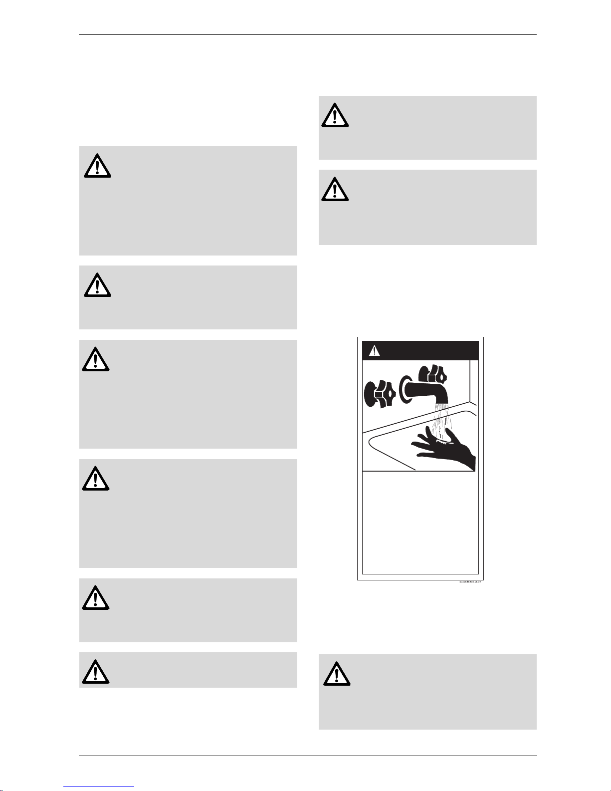
BURN
DANGER
Water temperature over 120°F can
cause severe burns instantly or
death from scalds.
Children, disabled and elderly are
at highest risk of being scalded.
See instruction manual before
setting temperature at water
heater.
Feel water before bathing or
showering.
HOT
6 720 646 804
4
Warnings
For installation in the state of California
California Law requires that residential water heaters
must be braced, anchored or strapped to resist falling
or horizontal displacement due to earthquake motions.
For residential water heaters up to 52 gallon capacity, a
brochure with generic earthquake bracing instructions
can be obtained from:
Office of the State Architect, 400 P Street,
Sacramento, CA 95814
or you may call 916.324.5315 or ask a water heater
dealer.
However, applicable local codes shall govern installation. For residential water heaters of a capacity greater
than 52 gallons, consult the local building jurisdiction
for acceptable bracing procedures.
The California Safe Drinking Water and Toxic Enforcement Act requires the Governor of California to publish
a list of substances known to the State of California to
cause cancer, birth defects, or other reproductive harm,
and requires businesses to warn of potential exposure
to such substances.
Proposition 65 Warning: this product contains a chemical known to the
State of California to cause cancer,
birth defects, or other reproductive
harm. This appliance can cause low-level exposure to some of the substances
included in the Act.
6 720 646 804
Appliance details
5
2 Appliance details
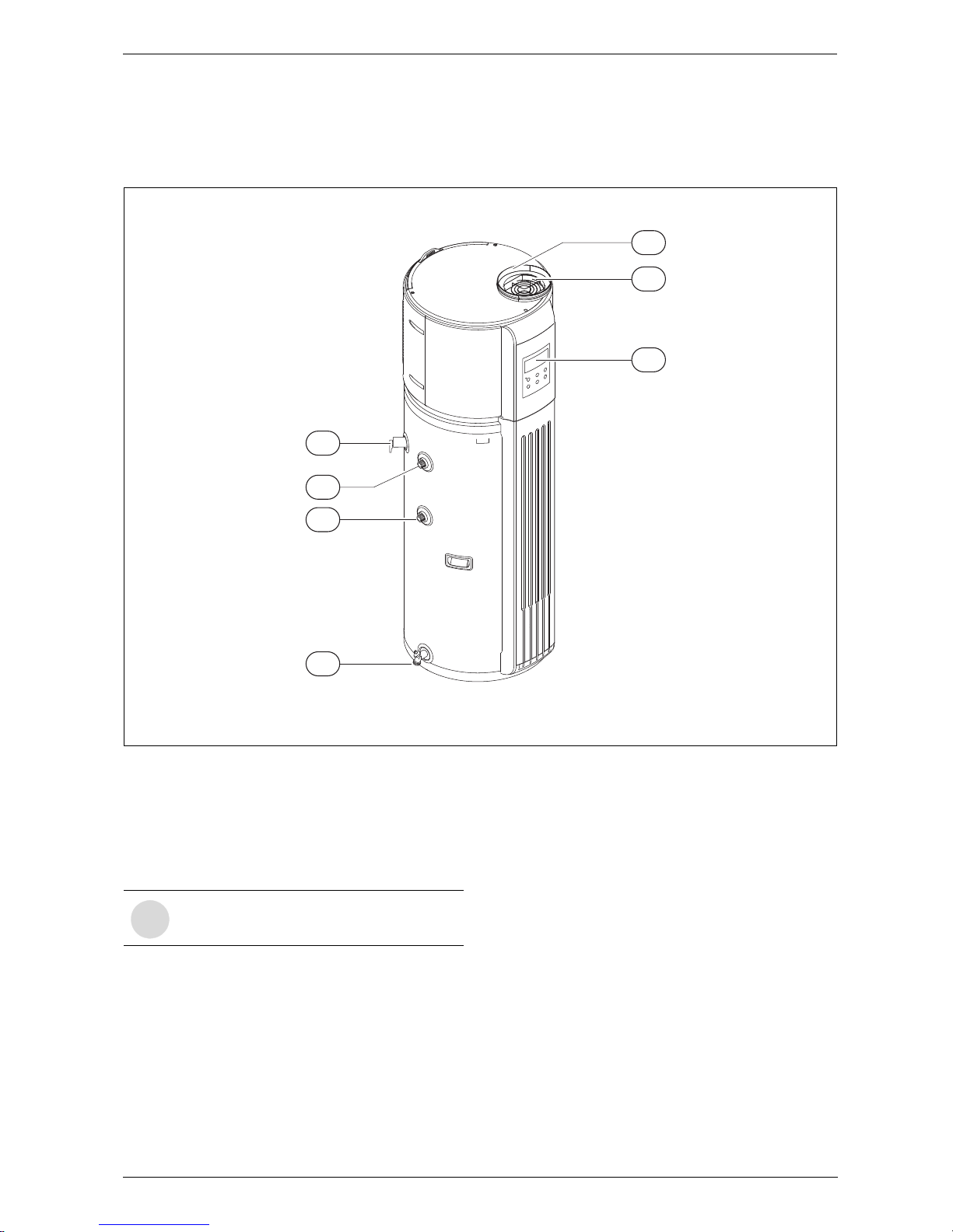
2.1 Overview
Fig. 2 Appliance overview
1 Temperature & pressure relief valve
2 Hot outlet
3 Cold intlet
4 Drain
5 Vent opening
6 Display
7 8" vent collar
2.2 Features and safety devices
Environmentally friendly and safe
Produces no harmful gas locally from the combustion of
oil, coal, or gas and is free of potential hazards from carbon monoxide.
Easy to operate and multiple heat sources
Easy to use adjustment keys for easy setting of the
water temperature. Depending upon the location of the
air exchanger, heat may be taken from a mechanical
room or a sun porch or attic space, or from hot areas in
any other domestic environments.
Heating capacity
The unit absorbs ambient energy and releases the heat
into the water stored in the tank. If the ambient temperature is low, the heating capacity of the heat pump will
be reduced, but you can still rely on the electrical elements for backup.
6
5
4
1
6720646804-04.1V
7
3
2
i
Vent collar does not come installed on the
water heater.
6 720 646 804
6
Appliance details
Temperature limiting controls (TCOs)
The water heater is equipped with two temperature-limiting controls (TCOs) that are located above the upper
heating heating element in contact with the tank surface. If for any reason the water temperature becomes
excessively high, the temperature-limiting control (TCO)
breaks the power circuit to the heating element. Once
the control opens, it must be reset manually. Resetting
of the temperature limiting controls should be done by
a qualified service technician.
Defrosting
Under the heating mode, the unit will shut down the
heat pump automatically if an unusually low temperature
is detected at the evaporator. This cycle can last
between 2 and 10 minutes and ensures maximum heating efficiency.
The fan motor will stop running when the unit is defrosting.
Working conditions
In order to use the unit correctly, please run the unit at
ambient temperature 45°F - 115°F.
The unit includes sophisticated electronic devices, care
should be taken to feed the unit only with potable water.
Do not use untreated water from lakes, rivers or
untreated groundwater!
Overheating protection
When the water temperature reaches 165°F power to
the unit will be cut off (see section 4.7 for instructions
on resetting the temperature limiter).
Water temperature or pressure protection
The unit is equipped with a T&P valve for your safety. If
the tank pressure reaches 150PSI or the temperature
reaches 210°F, the T&P valve will open automatically to
relieve the pressure and or reduce the temperature to
safe limits.
Caution: The cause of high
temperature conditions must be
investigated by a qualified service
technician and corrective action must
be taken before placing the water heater
in service again.
6 720 646 804
Appliance details
7
2.3 Specification tables
Model HP200-1E...
Running models Economy Auto E-heater
Running ambient temp. °F 45 - 115 45 - 115 -5 - 130
Outwater Temp. °F Default 120°,100°F - 140°F
Power supply Ph/V/Hz 1-240-60
Storage size US Gal 50
Water heating
Capacity kW / BTU/h 1.50 / 5123 1.50 / 5123 4.00 / 13661
Max. input kW / BTU/h 0.80 / 2732 4.50 / 15368 4.00 / 13661
First Hour Rating US Gal - 56.00 52.00
Max. current A 6.5 21.6 18.7
Ambient temp. °F - 5 - 130
Unit
Dimension (D×H) inch Ø22.4 × 64.5
Packing (W×H×D) inch 25 × 68.5 × 27
Weight lbs 209.4 / 242.5
Noise level dB(A) 48
Refrigerant type/quantity lbs R134a/1.7
Refrigerant design pressure PSIA 331/86 at ambient 70°F
Tank design pressure PSI 150
Throttling type Thermal expansion valve
System protection TCO, TDO, P&T valve, over-load protector temp.
ground fault protector etc.
Air flow Ft
3
/h 13066 / 9888 / 7063
Compressor
Model FFC110HBX
Type Piston
Brand Embraco
Input kW 0.7
Fan motor
Model YDK12-6B
Brand welling
Input W 40
Speed RPM 970/750/550
Water pipeline
Water inlet pipe Male NPT ¾
Water outlet pipe Male NPT ¾
Drainage pipe Hose fitting NPT ¾
PT valve joint Female NPT ¾
Max. pressure psi 145
Heat exchanger Dividing wall type heat exchanger
E-heater kW 4.0 × 2
Table 1
6 720 646 804
8
Appliance details
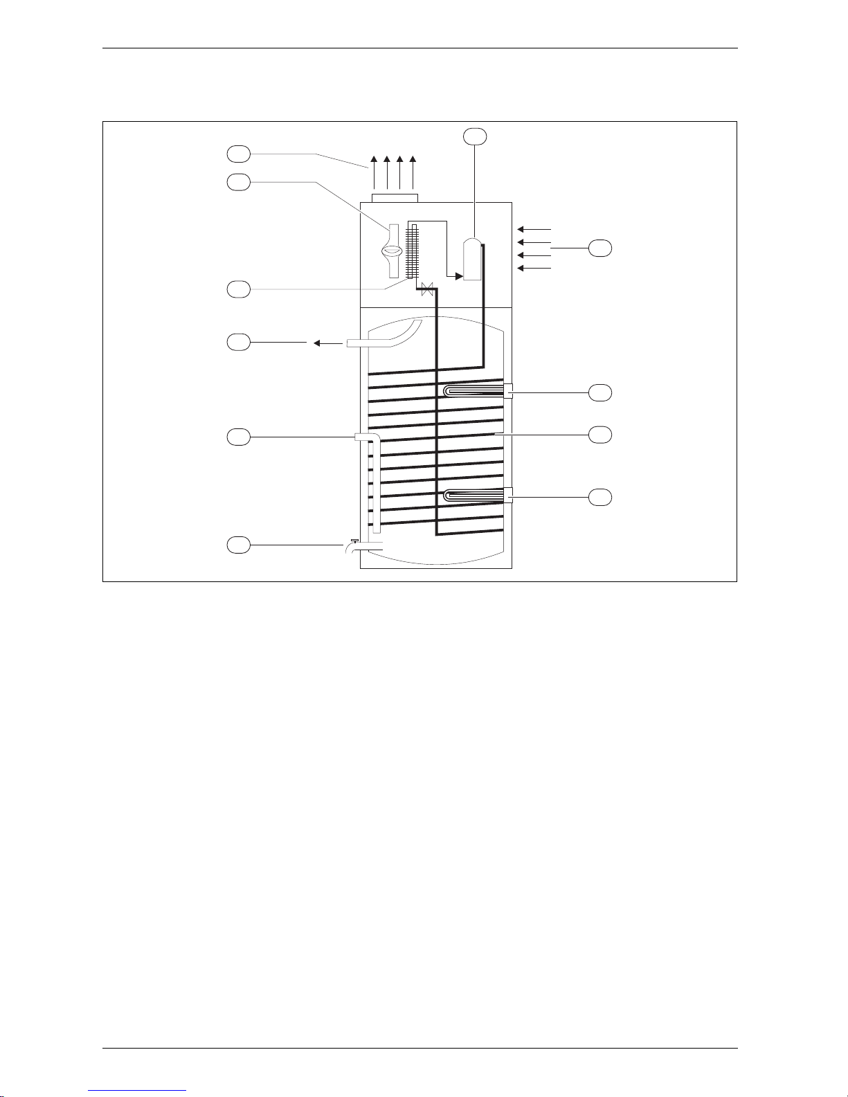
2.4 Principle of Operation (brief overview of modes)
Fig. 3
1 Air Heat Exchanger
2 Compressor
3 Cooled / Dehumidified Air
4 Upper/Lower Electric element
5 Condensor Coil (heat exchanger)
6 Drain valve
7 Domestic Hot Water outlet
8 Ambient Room Air
9 Fan
10 Cold water supply
System theory
An Electric Heat Pump Water Heater draws heat from
the ambient air and transfers that heat to the water in
the tank. Ambient air inside the room where the water
heater is installed is blown across an evaporator by a
fan. Cold refrigerant inside an expansion valve is heated
from this ambient air. This warmed refrigerant is then
sent through a compressor where it becomes extremely
hot. The hot refrigerant then passes through a
condenser coil that is wrapped around the outside of
the tank. The heat from the hot refrigerant is transferred
to the stored water inside the tank. After transferring it's
heat, the now warm refrigerant is pushed through an
expansion valve where it is cooled and depressurized so
the process can begin again. In addition, the ambient air
is cooled and dehumidified as it passes through the
evaporator and can be used to adjust the climate of the
room.
Built in controls offer a variety of operational modes to
suit every user’s needs. When operating with the heat
pump only (Economic Mode), the water is heated using
only the ambient air. Economic mode does not activate
the electric element inside. This mode may take longer
to heat the water to set temperature but uses less than
1/2 the electricity of a similar size electric tank.
The Auto mode use the electric element to supplement
the heat pump in the event that the water is not reaching
set temperature.
Electric mode allows for the water heater to function as
a standard electric tank without the use of the heat
pump.
Brief overview of modes
• Economic Mode;
• Electric Mode;
• Auto Mode (default mode);
• Vacation Mode.
9
3
7
6
5
2
8
6720646804-01.1V
4
4
1
10

6 720 646 804
Appliance details
9
2.5 Dimensions
Fig. 4 Dimensions (inches)
64.5
37.6
27.9
3.07
8
22.4
6720646804-03.1V
6 720 646 804
10
Installation instructions
3 Installation instructions
The manufacturer’s warranty does not cover any
damage or defect caused by improper installation,
attachment or use of any type of energy-saving or other
unapproved devices (other than those authorized by the
manufacturer) into, onto or in conjunction with the water
heater.
The manufacturer disclaims any responsibility for such
loss or injury resulting from the use of such
unauthorized devices.
3.1 Tools required
• Wrench ¾"
• Phillips screwdriver
• Flat screwdriver
• Wire strippers
• Level
• Measuring tape
• Standard plumbing tools.
3.2 Location requirements
Locate the water heater in a clean, dry area as near as
practical to the area of greatest hot water demand.
Long uninsulated hot water lines can waste energy and
water.
Note: Because this unit draws in air from the room to
heat the water, the room must be at least 10' x 10' x 7'
(700 cubic feet) or larger. If the room is smaller, there
must be louvers installed to allow for adequate airflow.
Place the water heater in such a manner that the air filter, cover and front panels can be removed to permit
inspection and servicing, such as removal of elements,
draining the tank, or cleaning of the filter.
The water heater and water lines should be protected
from freezing temperatures and highly corrosive atmospheres. Do not install the water heater in outdoor or
unheated, unprotected areas.
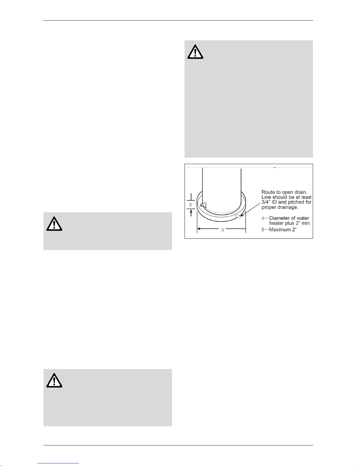
Fig. 5
NOTE: Auxiliary catch pan MUST conform to local
codes. Catch Pan Kits are available from the store
where the water heater was purchased, a building supply store or any water heater distributor.
Local installation regulations
This water heater must be installed in accordance with
these instructions, local codes, plumbing codes (UPC
or IPC), utility codes, utility company requirements or, in
the absence of local codes, the latest edition of the
National Electrical Code. It is available from some local
libraries or can be purchased from the National Fire Prevention Association, Batterymarch park, Quincy, MA
02169 as booklet ANSI/NFPA 70.
Required clearances
It is recommended that there is 5-½” of clearance (air
space) between any object and the front and rear
shrouds.
Warning: To avoid the potential for
ignition and fire, the water heater should
not be installed in a space where liquids
which give off flammable vapors are to
be used or stored.
Caution: The water heater should not
be located in an area where leakage of
the tank or connection will result in
damage. In installations where risk of
water damage cannot be avoided, a
suitable catch pan, adequately drained,
must be installed under the water
heater.
Warning: This water heater SHOULD
NOT be installed in a space where
liquids which give off flammable vapors
are to be used or stored. Such liquids
include gasoline, LP gas (butane and
propane), paint or adhesives and their
thinners, solvents or removers.
Because of natural air movement in a
room or other enclosed space,
flammable vapors can be carried from
where their liquids are being used or
stored. Any arc within the water
heater's electronic controls can ignite
these vapors causing an explosion or
fire which may result in severe burns or
death to those in range, as well as
property damage.
6 720 646 804
Installation instructions
11
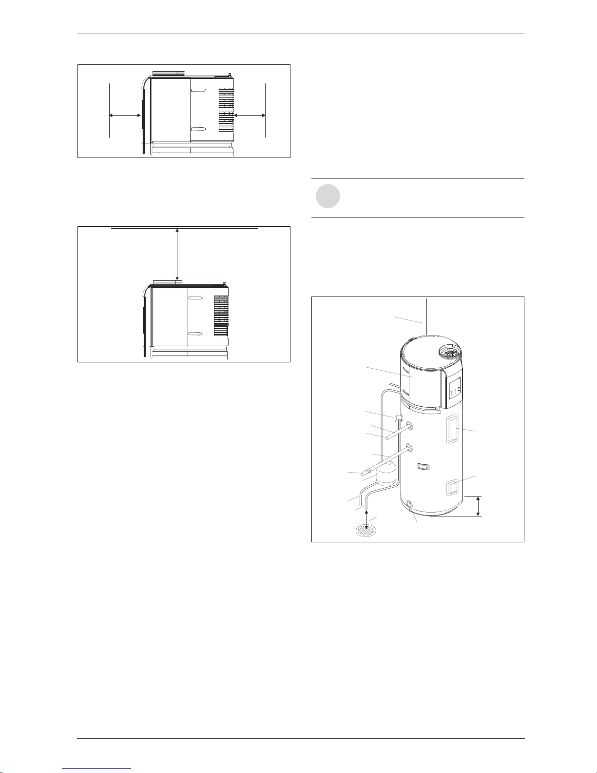
Fig. 6
A 27” minimum vertical clearance is required to remove
the filter for cleaning and to replace the anode rod. The
hot and cold water plumbing and electrical connections
must not interfere with the removal of the filter.
Fig. 7
Condensation drain
The unit has a condensate drain, therefore a drain must
be available in close proximity to the unit. The drain must
be no higher than 36” above the floor (laundry drain is
acceptable).
If no drain is available, then a common condensate
pump with a capacity no less than 1 gallon/day must be
purchased from a local builder and supply store and
installed.
3.3 Venting (specifications and vent
runs)
Venting the outlet air of the water heater to another
room may be an option for specific applications. See
Section 3.6.
• Duct diameter: 8”
• Maximum outlet duct length: 16.5 feet
• Maximum Air flow: 219 CFM
• Maximum no. of elbows: 1.
The vent collar accessory (see Fig. 2) must be installed
in order to accommodate the required 8" diameter vent
pipe. Line up tabs on vent collar with slots in vent
opening. Rotate to lock into place.
If terminating venting to the outdoors, pitch horizontal
pipe downward towards termination 1/4" per foot to
avoid damage from rain.
3.4 Water piping
3.4.1 Inlet - Outlet connections
Refer to the illustration below for suggested typical
installation. The installation of unions or flexible copper
connectors is recommended on the hot and cold water
connections so that the water heater may be easily disconnected for servicing if necessary. The HOT and
COLD water connections are clearly marked and are
¾”NPT on all models.
IMPORTANT: Do not apply heat to the HOT or COLD
water connections. If sweat connections are used,
sweat tubing to adapter before fitting the adapter to the
water connections on heater. Any heat applied to the
hot or cold water connection will permanently damage
the dip tube.
Fig. 8 Typical installation
3.4.2 Dielectric union (recommended accessory)
Different metals between plumbing and tank materials
and additionally the effect of hot water can cause
corrosion of one of the metals (generally the one in the
tank is the metal attacked)
The Dielectric union will avoid any physical contact
between the two metals, acting as an effective insulator
and preventing this attack. How quick this corrosion
progresses, if at all, depends on the content of your
water, its pH, the dissolved minerals and the metals
involved.
5”½5”½
6720646804-06.1V
27”
6720646804-05.1V
i
Install a shut-off valve in the cold water line
near the water heater. This will enable easier service or maintenance of the unit later.
6720646804-09.1V
6” air gap
Relief discharge
line to suitable
open drain
6’ drain hose
Thermal expansion
tank (if required)
To cold water
supply
Hot water outlet
to fixtures
Union
Union
Temperature and
pressure relief valve
(shown in different
location for clarity)
Drain valve
Jacket
access panel
Jacket
access panel
Auxiliary catch
pan 2” maximum
Electrical junction box
(use only copper
conductors)
To electrical
distribution panel
6 720 646 804
12
Installation instructions
Failing to install this accessory will void the tank
warranty.
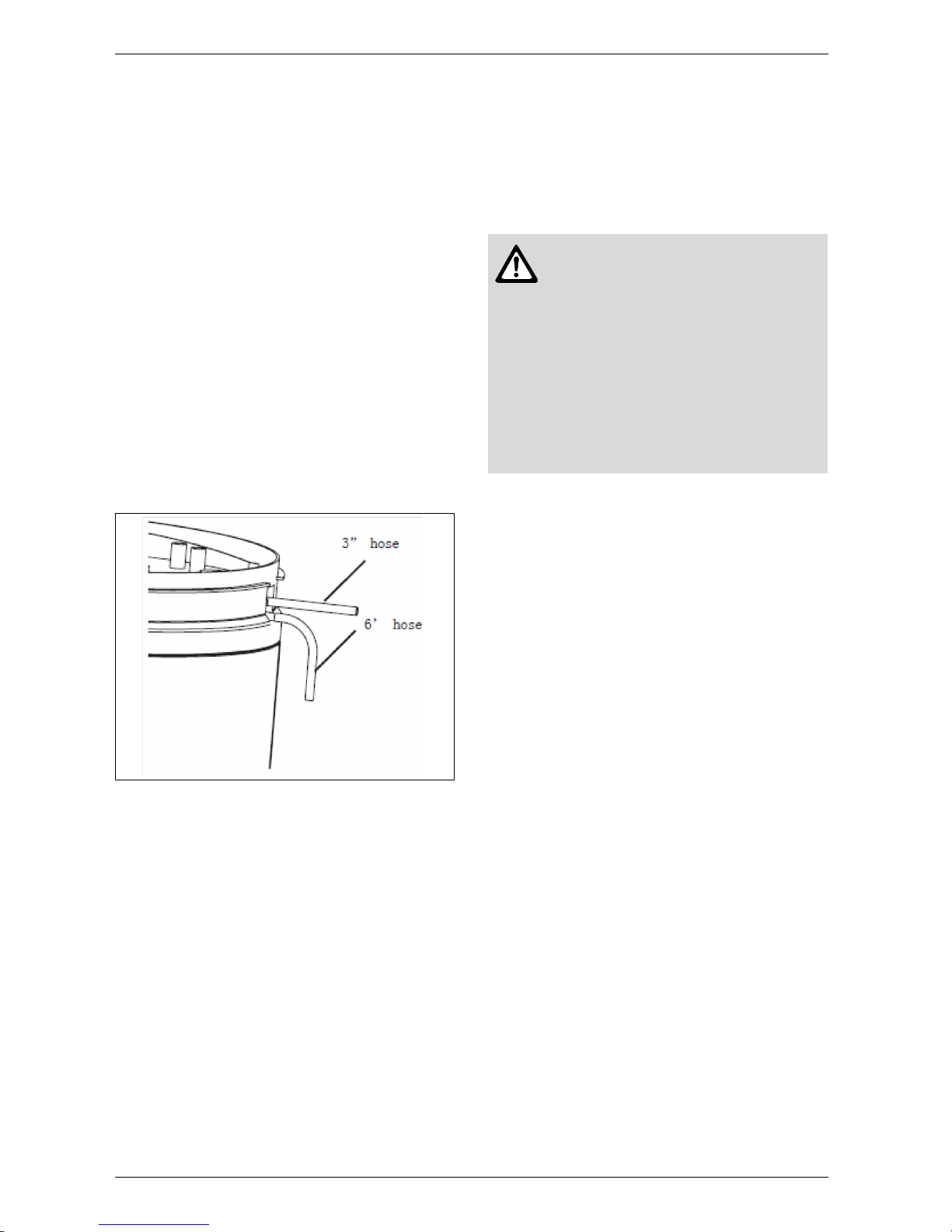
3.4.3 Condensate Drain Tubes
This unit has a condensation tray. The water collected
in the tray drains out of the drain ports coming off the
back of the unit. Two flexible hoses are included with
this unit. It is important that both of these hoses are
attached to the two drain ports coming off the back of
the unit. The upper drain serves as an overflow drain
that will operate only if the bottom drain is blocked.
Water leaking from the upper drain is an indicator that
the lower drain, and possibly the condensate pan itself,
require cleaning.
B Attach one end of the longer 6’ hose to the lower
drain port on the back of the unit, underneath the rear
cover.
B Direct the other end to a drain in the floor or no higher
than 3’ above the floor.
If such drain is unavailable, a condensate drain pump
(not provided) must be purchased and installed.
B Attach the shorter 3” hose to the top drain port.
Fig. 9
3.4.4 T&P Valve
A combination temperature and pressure-relief valve,
complying with the Standard for Relief Valves for Hot
Water Supply Systems, ANSI Z21.22, is supplied and
must remain installed in the opening provided and
marked for the purpose on the water heater. No valve of
any type should be installed between the relief valve and
the tank. Local codes shall govern the installation of
relief valves.
Connect the outlet of the relief valve to a suitable open
drain so that the discharge water cannot contact live
electrical parts or persons and to eliminate potential
water damage. Under no circumstances should the
relief valve vent be connected to the condensate drain
line.
Piping used should be of a type approved for hot water
distribution. The discharge line must be no smaller than
the outlet of the valve and must pitch downward from
the valve to allow complete drainage (by gravity) of the
relief valve and discharge line. The end of the discharge
line should not be threaded or concealed and should be
protected from freezing. No valve of any type, restriction, reducing coupling or tee should be installed in the
discharge line.
This valve must be marked with a maximum set pressure
not to exceed the marked maximum working pressure of
the water heater. It should be installed into an opening
provided and marked for this purpose in the water
heater, and vented so that any discharge from the valve
exits only within 6 inches above, or at any distance
below, the structural floor, and does not contact any live
electrical part. The discharge opening must not be
blocked or reduced in size under any circumstances.
3.4.5 Thermal expansion tank
Determine if a check valve exists in the inlet water
supply line. It may have been installed in the cold water
line as a separate backflow preventer, or it may be part
of a pressure-reducing valve, water meter or water
softener. A check valve located in the cold water inlet
line can cause what is referred to as a "closed water
system". A cold water inlet line with no check valve or
backflow prevention device is referred to as an "open"
water system.
As water is heated, it expands in volume and creates an
increase in the pressure within the water system. This
action is referred to as "thermal expansion". In an
"open" water system, expanding water which exceeds
the capacity of the water heater flows back into the city
main where the pressure is easily dissipated.
A "closed water system", however, prevents the
expanding water from flowing back into the main supply
line, and the result of "thermal expansion" can create a
rapid and dangerous pressure increase in the water
heater and system piping. This rapid pressure increase
can quickly reach the safety setting of the relief valve,
causing it to operate during each heating cycle. Thermal
expansion, and the resulting rapid and repeated
expansion and contraction of components in the water
heater and piping system, can cause premature failure
Warning: To reduce the risk of
excessive pressures and temperatures
in this water heater, install temperature
and pressure protective equipment
required by local codes and no less
than a combination temperature and
pressure relief valve certified by a
nationally recognized testing laboratory
that maintains periodic inspection of
production of listed equipment or
materials, as meeting the requirements
for Relief Valves for Hot Water Supply
Systems, ANSI Z21.22.
 Loading...