


CLIMO A D00 A40 103
Micro Climate Monitoring System
BOSCH CLIMO

A D00 A49 029
|
2017-06-09 Robert Bosch Engineering and Business Solutions Private Limited
Table of Contents
1.
Symbols and safety precautions
3
1.1 Explanation of symbols 3
1.1.1 Warning notices Structure and meaning 3
1.2 Symbols in this documentation 3
1.3 On the product 3
5.
User Interface 15
5.1 Air Quality Index 15
5.2 User Interface 15
5.3
Interpreting the outputs 15
5.3.1 To access the device through Web app 15
1.4 Important safety instructions 3
1.5
Important Notices 4
6. Troubleshooting 15
1.5.1 Don'ts 4
1.5.2
Environmental statement 4 7. Maintenance 16
1.5.3
Moving 4
1.5.4
Unpacking 4
1.5.5
3/CP300H (3.6V NI-MH BATTERY) &
8. Recommendations 16
8.1 Disposal 16
CR2032H BATTERY: 4
1.6
Enclosure safe handling instructions 5 9. Warranty 16
1.7 Short information 5
10.
FCC Warning statement 15.19
17
2.
BOSCH CLIMO overview
6
2.1
Version of product 6 11. FCC Warning statement 15.105 17
2.2 Applications 6
2.3
Site & Parameter selection as per CPCB
guidelines on measurement of Ambient Air
12.
Statement
17
Pollutants (Air Quality) 6
2.4
Device specifications 7 13. Mobile Device 17
2.5 Technical data 8
14.
RED Requirement
17
3.
Pre Installation
9
3.1 Installation Kit
9
3.2 Tools
9
3.3 Torque table
9
3.4 SIM insertion (for Micro Climate Monitoring
System 3G variant AD00 A40 00)
9
3.5 configuration (Micro Climate Monitoring
System
variant AD00 A40 002
9
3.6 Ethernet and USB connectors
9
3.6.1
Panel mount
connectors
9
3.6.2
Mating
connectors
9
3.7 Calibration
10
3.8 Health indicators
10
3.9 Pre installation Acc
eptance checklist
10
3.10 Post installation Acceptance checklist
11
4. Installation
12
4.1 Unpacking
12
4.2 Installing SIM
12
4.3 Mounting bracket assembly
12
4.4 Pole mounting
13
4.5 Wall mounting
13
4.6 Sun shade and UV sensor assembly
13
4.7
Splash guard and CO
sensor assembly
14
4.8 AC DC connection
14
en 2 |
A D00 A49 029 | 2017-06-09Robert Bosch Engineering and Business Solutions Private Limited
|
1.
Symbols and safety
precautions
1.1
Explanation of symbols
1.1.1 Warning notices Structure and meaning
Warning notices warn of dangers to the user or people
in the vicinity. Warning notices also indicate the
consequences of the hazard as well as preventive action.
Warning notices have the following structure:
Abbreviations used in this manual:
Warning
symbol
KEY WORD – Nature and source of hazard!
Consequences of hazard in the event of failure
to observe action and information given.
➢
Hazard prevention action and information.
The key word indicates the likelihood of occurrence and
the severity of the hazard in the event of non-observance
Key word Probability of
occurrence
Severity of danger if
instructions not observed
DANGER
Immediate
impending
danger
Death
or
severe
injury
WARNING
Possible
impending
danger
Death
or
severe
injury
CAUTION
Possible
dangerous
situation
Minor
injury
1.4
Important safety instructions
Read, follow, and retain for future reference all of the
following safety instructions before operating the unit.
•
Do not install or store the unit near any heat sources
such as radiators, heaters, stoves, or other equipment
(including amplifiers) that produce heat.
•
Do not block or cover any of the openings provided in
the unit. They are provided for ventilation, to prevent
from overheating and to ensure reliable operation.
Keep open distance of approximate 200mm all round
the unit.
•
Do not place objects filled with liquids, such as vases
or cups on the unit. Never spill liquid of any kind on
the unit.
•
Do not open the mating connector and dust cap in rainy
1.2
Symbols in this documentation
Symbol Designation Explanation
!
Attention Warns about possible property damage.
i
Information
Practical hints and other useful
information.
1.
2.Multi-step
operation
Instruction consisting of several steps.
1.3
On the product
!
Observe all warning notices on products and ensure
they remain legible.
season, as the water might enter the unit and lead to
fire or electrical shock.
•
Disconnect the electrical connection before cleaning.
Use only a dry cloth. Do not use liquid cleaners or
aerosol cleaners.
•
Do not attempt to service a damaged device yourself,
unless qualified. Contact your associated channel
partner for all types of servicing, such as
–
The power supply cord or plug is damaged;
–
Sensor damaged due to exposure of moisture,
water, and/or inclement weather (rain, snow,
etc.);
–
Liquid has been spilled in or on the equipment;
–
Unit has been dropped or the unit cabinet is
damaged;
–
Unit exhibits a distinct change in performance;
–
Unit does not operate normally when the user
correctly follows the operating instructions.
•
Install in accordance with the manufacturer's
instructions in accordance with applicable local
codes.
•
Use only attachments or accessories specified by
the manufacturer. Equipment change or modification
could void the user's guarantee or authorization
agreement.
Symbols and safety precautions | 3 en
AQI
Air Quality Index
IoT
Internet of Things
IP
Ingress Protection
PCB
Printed Circuit Board
PSK
Pre-Shared Key
SIM
Subscriber Identity Module
A D00 A49 029
|
2017-06-09
Robert Bosch Engineering and Business Solutions Private Limited
•
Be sure that the service technician uses replacement
parts specified by the manufacturer, or that which
have the same characteristics as the original parts.
Unauthorized substitutions may cause injuries or
other hazards.
i
The IMPORTANT SAFEGUARDS and WARNINGS
presented in this manual do not cover all possible
conditions that may occur. Common sense, caution
and care must be exercised when installing,
maintaining or operating the unit.
1.5
Important Notices
Accessories - Do not place this unit on an
unstable stand, tripod, bracket, or mount.
The unit may fall, causing serious injury
and/or serious damage to the unit. Use
only with mounting solutions specified
by the manufacturer. When a cart is used,
use caution and care when moving the
cart/unit combination to avoid injury from
tip-over. Quick stops, excessive force, or
uneven surfaces may cause the cart/unit
combination to overturn. Mount the unit as
per the installation instructions. .
1.5.1 Don'ts
•
Do not connect the unit to the electrical power supply
using cables that have been damaged.
•
Do not remove any of the connectors.
•
Do not keep the unit below water body and water
pipes.
•
Do not keep the unit in temperature range other than
indicated in recommendation section.
•
Do not power the unit with other power sources than
the original provided by RBEI. Voltage and current
maximum ratings can be exceeded, stopping unit from
working and voiding warranty.
•
Do not try to extract, screw, break or move connectors
far from necessary usage, waterproof sealing can be
damaged and warranty will be voided.
•
Do not connect any sensor not provided by RBEI.
•
Do not place nodes on places or equipment where
it could be exposed to shocks and/or big vibrations.
•
Do not keep mating connectors or dust caps in unlock
condition.
•
Do not use dropped unit.
•
Do not replace the sensor or any parts in the mounting
condition.
•
Do not carry the unit in assembled condition (with sun
shade, splash guard, hose clamp and screw hardware).
•
Do not mishandle CO2 and UV sensor as it may cause
reading disturbance due to vibration or shock.
1.5.2 Environmental statement
Bosch has a strong commitmenttowards the environment.
This unit has been designed to respect the environment
as much as possible.
1.5.3 Moving
Disconnect the power before moving the unit. Move the
unit with care. Excessive force or shock may damage the
unit.
1.5.4 Unpacking
•
This equipment should be unpacked and handled
with care. If an item appears to have been damaged in
shipment, repack it in the original packaging and notify
the shipping agent or supplier immediately.
•
Verify that all the parts listed in the parts list below
are included. If any items are missing, notify your RBEI
representative.
•
The original packing carton is the safest container to
transport the unit and must be used if returning the
unit for service. Save it if possible, for future use.
1.5.5 3/CP300H (3.6V NI-MH BATTERY) & CR2032H
BATTERY:
Caution:
Risk of explosion if battery is replaced by an
incorrect type.
Dispose of used batteries (3/CP300H & CR2032H
battery) according to the instructions.
Refer section 8.1
en 4 | Symbols and safety precautions
A D00 A49 029 | 2017-06-09
Robert Bosch Engineering and Business Solutions Private Limited
|
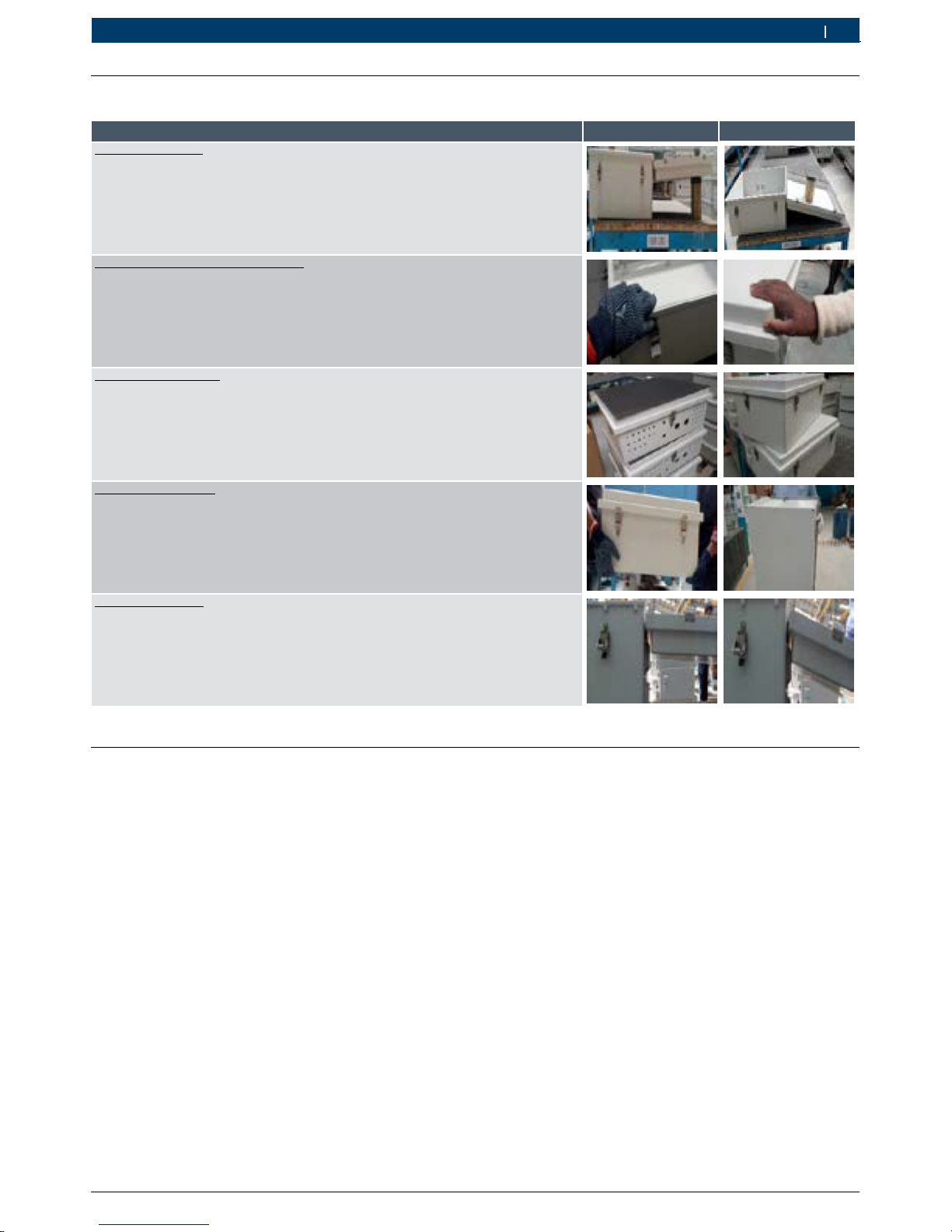
1.6
Enclosure safe handling instructions
Alert type
Do'
s
Don'ts
No load on hinges
Do’s:
Always provide support at the bottom side for enclosure cover, in cover open
condition to avoid load on hinges.
Don’ts:
Do not keep enclosure cover without proper support. Do not keep any load
on enclosure cover from inside.
Cotton gloves for product handling
Do’s:
Always use clean hand gloves to handle the enclosure.
Don’ts:
Do not touch the enclosure with bare hands and dirty gloves.
Stacking of enclosure
s
Do’s:
Use spacer material (preferably foam) to stack empty enclosure.
Don’ts:
Do not stack empty enclosure without any spacer material in-between.
Stacking of assembled enclosures are not recommended.
Enclosure movement
Do’s:
Hold horizontally and ensure support from all the sides during hand carry of
enclosures. 4 hands support for larger size (control series) is a must.
Don’ts:
Do not hold enclosure in vertical position and hand carry.
Load on vent kits
Do’s:
Enclosure covers are to be placed at 180° with bottom support.
Don’ts:
Do not rest enclosure cover on vent kits. Do not rest enclosure itself on vent kit.
1.7
Short information
All efforts have been made to ensure the accuracy of material provided in this document at the time of release. However,
the items described in this document are subject to continuous development and improvement. All specifications
are subjected to change without notice and do not represent a commitment on the part of Robert Bosch Engineering
and Business Solutions Private Limited (RBEI). RBEI will not be responsible for any loss or damages incurred related
to the use of information contained in this document.
!
Before starting up, connecting and operating this product, it is absolutely essential that the installation instructions
and, in particular, the safety instructions are studied carefully. By doing so, any uncertainties in handling this
product can be eradicated and will ultimately help to avoid damage to the unit.
Copyright
This manual is the intellectual property of RBEI and is protected by copyright.
All rights reserved.
Trademarks
All hardware and software product names used in this document are likely to be registered trademarks and must
be treated accordingly.
Symbols and safety precautions | 5 en
A D00 A49 029
|
2017-06-09 Robert Bosch Engineering and Business Solutions Private Limited
2.
BOSCH CLIMO overview
BOSCH CLIMO is designed to measure certain
atmospheric gases and factors of the ambient
environment.
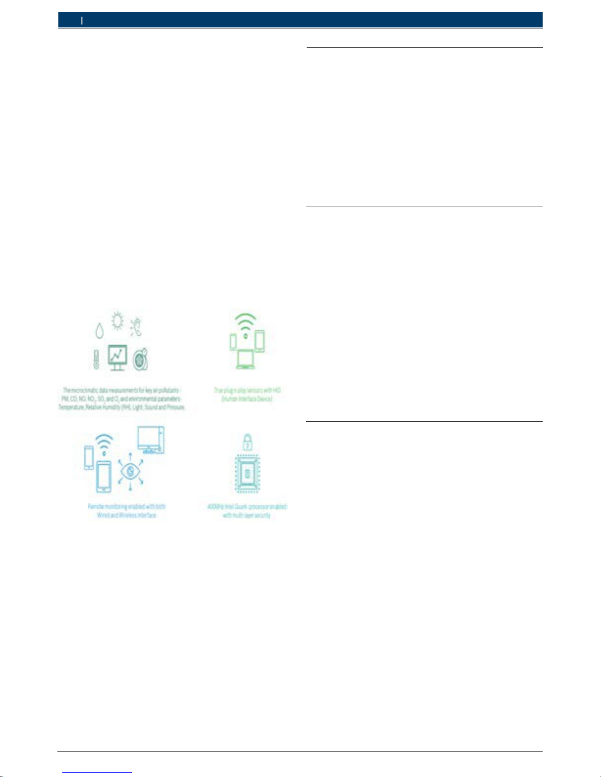
BOSCH CLIMO features are:
2.1 Version of product
There are four versions of product that is available for
customer based on connectivity;
•
Micro Climate Monitoring System (SC_3G)
A D00 A40 103
•
Micro Climate Monitoring System (3G)
A D00 A40 100
•
Micro Climate Monitoring System
A D00 A40 101
•
Micro Climate Monitoring System (Standard- RJ45)
A D00 A40 102
•
It is easy to deploy, technologically advanced and
incurs zero added infrastructure investment.
•
It connects compact wireless sensors over
3G networks enabling micro-climatic data collection.
•
BOSCH CLIMO is powered with the state-of-the-art
IoT-friendly Intel Quark processor enabled with a
“pattern matching” technology; facilitating energyefficiency, scalability and sustainability for real-world
applications.
i
Whilst robust in design, the unit is a sensitive piece
of scientific equipment and should be treated as
such.
!
The device must be protected from strong direct
sunlight as this will quickly raise the temperature of the
device beyond its operating range. BOSCH CLIMO unit
has been provided with a sun shade guard to protect
from the effects of sunlight.
i
Mount the unit facing North or South direction
!
There will be variation in sensor behavior due to
limitation of NO, NO2, and O3 sensors on higher
temperature range beyond 40°C and PM sensor for
below -10°C.
2.2 Applications
•
Real Estate and Community:
BOSCH CLIMO will
be the indicator for quality of life index and the
breathability of the ambient air. The recommendations
and early warning system based on air profiling will
help the society to make smarter choices.
•
Smart Cities:
It will form a mandatory component for
any smart city as it aides in awareness and better city
management.
•
Industries Construction:
It assists in perimeter
monitoring of the site, measure the factory health
and determines the condition in which the workers
are working.
•
Mining and Oil and Gas: This is a heavily polluting
sector by the nature of the industry itself. BOSCH
CLIMO will help in compliance adherence by constant
monitoring and thus making it a greener sector.
2.3 Site & Parameter selection as per
CPCB guidelines on measurement of
Ambient Air Pollutants (Air Quality)
Site Selection
•
Away from source & other interferences (inlet 15m
away from source/traffic artery).
•
Height of inlet >3m (preferably 3-10m) Double the
height of nearby wall/obstructed.
•
Free flowing, well mixed.
•
Elevated angle <30 (from inlet to top of building).
•
Collocated samplers should be 2m apart.
Parameter Selection
•
Sensitive location (SO2 & NO2).
•
Health Impact stations (All pollutants).
•
Population & exposure (All criteria pollutants).
•
Kerb side (Traffic intersection) (criteria pollutants +
CO).
•
Downtown (Accumulative, 50 m away traffic
intersection) (criteria pollutants + O3).
en 6 | BOSCH CLIMO overview
 Loading...