


D371B/D371C
Installation Instructions
24 V/110 V Floor Mount
EN Door Holder
D371B/D371C | Installation Instructions | 1.0 Overview
Notice
Carefully follow these instructions to prevent damage to the equipment.
Installation Standards
Install, test, and maintain the D371B/D371C according to these instructions, the National Fire Protection Association (NFPA) 72, local codes, and the authority having jurisdiction (AHJ).
Failure to follow these instructions can result in the failure of the D371B/D371C to operate in alarm.
Bosch is not responsible for improperly installed, tested, or maintained devices.
1.0 Overview
Use these instructions to install the D371B/D371C 24 V/110 V Floor Mount Door Holder.
The installation procedure includes:
•Installing the floor-mounted bracket,
•Attaching the backbox to the bracket,
•Connecting the electromagnet to the circuit wiring,
•Installing the electromagnet in the backbox, and
•Installing the catch plate.
The D371B/D371C operates on 24 VDC, 24 VAC, or 110 VAC. It provides up to 110 lb (49.9 kg) of holding force for fire door or other magnetic applications.
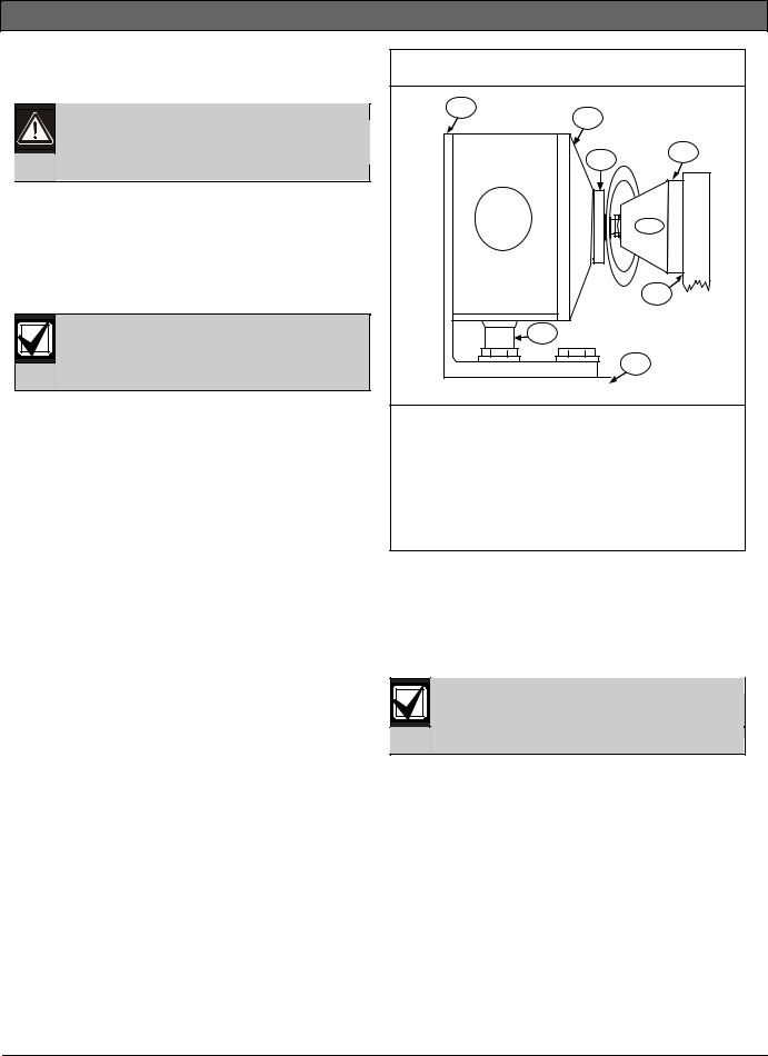
Each door holder includes all hardware necessary to install the floor-mount bracket, attach the backbox to the bracket, mount the electromagnet in the backbox, and attach the catch plate to a standard door. Install the bracket on a door that swings open to within 5 in. (12.7 cm) of a single gang backbox (Figure 1).
Figure 1: D371B/D371C Installation – Plan View
1
2
4
3
5
7
6
1 - Bracket
2 - D371B/D371C Electromagnet
3 - D371B/D371C Catch Plate
4 - Swivel base
5 - Door
6 - Floor
7 - Conduit
Use extension rods if the door does not swing open within 5 in. (12.7 cm) of the backbox. Extension rods are available in lengths of 1 in. to 4 in. (2.5 cm to
10 cm). The 40 in. (10 cm) hinged extension rod compensates for misaligned catch plates and electromagnets.
Use the D378 Extension Rod Wrench when installing extension rods.
2 |
Bosch | 2/06 | 33852C |

D371B/D371C | Installation Instructions | 2.0 Installation
2.0Installation
2.1Installing the Floor-Mount Bracket
Verify the bracket mounting can withstand the stress the door exerts on it through the D371B/D371C Electromagnet.
The D371B/D371C is packaged with the backbox mounted on the bracket. The backbox accepts electrical conduit through knockouts at the top, bottom, and back (Figure 2).
Figure 2: D371B/D371C Bracket Mounting
|
1 |
2 |
2 |
1 - Floor-mount bracket
2 - Floor mounting anchor screws (4)
1.Remove the four backbox mounting screws.
2.Position the bracket so the backbox aligns with the catch plate location on the door. Refer to
Section 2.4 Mounting the Catch Plate to the Door on page 5 for the catch plate location and alignment.
3.Securely mount the bracket to the floor.
2.2Attaching the Backbox to the Bracket
Refer to Figure 3 when attaching the backbox to the bracket.
Figure 3: |
Backbox to Bracket Mounting |
|
|
1 |
2 |
|
|
3 |
|
|
4 |
1 - Floor mount bracket |
||
2 - |
Backbox |
|
3 - |
Backbox screws (4) |
|
4 - |
Anchor screws (4) |
|
1.Mount the backbox to the bracket and connect the wiring conduit.
2.Pull the circuit wiring through the conduit and into the backbox.
The D371B/D371C operates on 24 VDC, 24 VAC, or 120 VAC. The D371B/D371C terminals accept wires between 12 AWG (2.3 mm) and 22 AWG (0.8 mm).
You can wire 120 VAC to either Terminal L or Terminal H depending on the required holding force (Table 1).
Table 1: |
Specifications |
|
|
|||
|
|
|
|
|
|
|
|
|
|
|
|
|
|
Input |
|
|
Terminal |
Current |
Holding |
|
Voltage |
|
|
Connections |
Draw |
Force |
|
24 VDC nominal |
C&L |
20 mA |
40 lb |
|||
(18 VDC to |
|
|
|
|
(18 kg) |
|
30 VDC) |
|
|
|
|
|
|
24 VAC nominal |
C&L |
19 mA |
40 lb |
|||
(18 VAC to |
|
|
|
|
(18 kg) |
|
30 VAC) |
|
|
|
|
|
|
|
120 VAC nominal |
|
C&H |
20 mA |
35 lb |
|
|
(90 VAC to |
|
|
|
|
(16 kg) |
|
150 VAC) |
|
|
|
|
|
120 VAC nominal |
C&L |
100 mA |
110 lb |
|||
(90 VAC to |
|
|
|
|
(50 kg) |
|
150 VAC) |
|
|
|
|
|
|
|
|
|
|
|
|
|
Terminal C = Common
Terminal L = Low voltage
Terminal H = High voltage
Bosch | 2/06 | 33852C |
3 |
 Loading...