Bosch D7035, D7035B Installation Manual

D7035/D7035B |
Octal Relay Module |
|
|
Installation Guide
1.0Notice
These instructions cover the installation of the Radionics D7035/D7035B Octal Relay Modules in a fire system supervised by a Radionics D7024 Fire Alarm Panel (FACP).
Install, test and maintain the D7035/D7035B according to their instructions, NFPA 72, Local Codes and the Authority Having Jurisdiction. Failure to follow these instructions may result in failure of the device to operate properly. Radionics is not responsible for improperly installed, tested or maintained devices.
These instructions contain procedures to follow in order to avoid personal injury and damage to equipment.
2.0Device Description
The D7035/D7035B is an Octal Relay Module that provides eight Form “C” relay outputs for addition to the D7024 Control. It connects to the D7024 via the Option Bus. The outputs are fully programmable, and can be activated by several system events. Each output operates individually of the other seven outputs for complete flexibility.
3.0Installation
Before installing the D7035/D7035B, disconnect all power (AC and battery) from the control panel.
3.1Installing the D7035 inside the FACP Enclosure
Use the following steps when installing the D7035 inside the FACP enclosure:
1)Remove the two optional transformer studs from the enclosure using either pliers or a hammer to rock them loose. Push the studs back through the enclosure. If the enclosure is already mounted, pull the studs forward through the back of the enclosure instead of pushing them back. See Figure 1 for details.
|
D7024 Control Board |
|
Mounting Location |
Side View of Enclosure |
|
D7024 PCB |
Mounting Clip |
|
|
|
for D7024 |
|
Use pliers (or a hammer) |
|
to remove these two |
|
optional transformer studs. |
Lip |
Chassis |
|
Brackets |
D7024 |
|
|
|
Route D7035 field wiring |
|
D7035 |
through side enclosure |
Mounting Clip |
Mounting |
knockout. |
for D7035 |
Location |
|
|
|
D7035 |
|
|
Mounting Clips |
Figure 1: Installing the D7035 in the D7024 Enclosure
2)Place the mounting clips in the enclosure as shown in Figure 1.

D7035/D7035B
Installing the D7035/D7035B
3)Insert the upper length of the D7035 board underneath the lips of the mounting clips holding the control panel board in place. See Figure 1.
4)Fasten screws through the lower mounting holes on the D7035 and mounting clips from step 3. See Figure 1.
5)Refer to section 4.0 for wiring instructions.
3.2Installing the D7035B Outside the FACP Enclosure
The preferred mounting for the D7035 is directly inside the FACP enclosure, using the provided mounting site. The D7035B kit (which contains a D7035 Octal Relay Module, one MP-D203 Mounting Skirt, and one AE203R Fire Enclosure) may, however, be mounted in its own enclosure near the FACP using the following procedure.
 Refer to the FACP’s installation manual to determine the maximum wire length between the panel’s option bus
 and the D7035 Octal Relay Module. No more than 4,000 ft. (1,219 m) of wire may be attached to the FACP option


 bus terminals.
1)Choose an appropriate location for the AE203R enclosure.
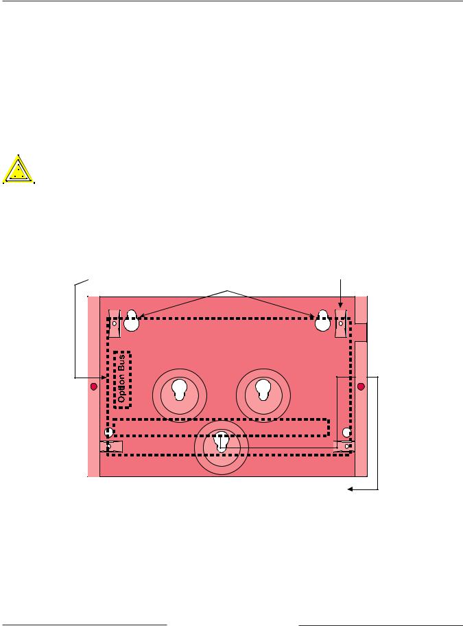
2)Using the enclosure as a template, mark the mounting holes on the mounting surface and make openings for the unit’s wiring. It is recommended that the option bus wiring enter the AE203R enclosure from the left and the D7035 output wiring exit the enclosure to the right. See Figure 2.
Route option bus wiring |
Attach mounting skirt to |
(power-limited) through |
the four enclosure lances |
left-side knockout |
Mounting Holes |
Output Terminals |
Output Terminals |
Route field wiring (non power-limited) through right-side knockout
Figure 2: Mounting the AE203R Enclosure
3)Snap the four plastic standoffs onto the appropriate raised tabs on the mounting skirt (see Figure 3) and then use the longer supplied screws to attach the D7035 module to the plastic standoffs.
|
D7035/D7035B Installation Guide |
|
PRELIMINARY 37280F |
Page 2 |
Copyright © 2002 Radionics |
 Loading...