Bosch D7412GV4-A, D8108A Installation Manual

D8108A |
Attack Resistant Enclosure |
|
|
Installation Instructions
1.0 Description
The D8108A Attack Resistant Enclosure houses many Bosch Security Systems control panels. When housed in a D8108A, a listed control panel can be used in a high-security mercantile alarm application. For specific control panel applications, refer to the operation and installation manual for the control panel you are using.
2.0 Installation
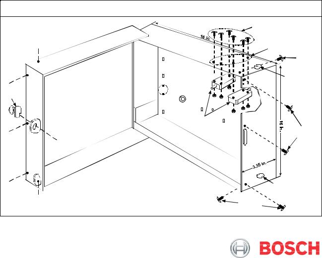
Two knockouts in the D8108A base (one in the top, the other in the bottom) accommodate ¾ in. (2 cm) conduit. The D8108A door is slotted to enable conduit access.
The hardware (assembly required) includes:
•Two tamper switches
•Six 1 in. (2.5 cm) 6-32 screws and six nuts (for the tamper switches)
•Five 7/8 in. (2.2 cm) 8-32 machine screws
•One lock and key (P/N: 60-01340-001)
1.Attach the lead wires to the terminals on the two tamper switches and wire them in series with an EOL resistor.
2.Using the supplied hardware, screw the tamper switches to the enclosure (screws on the outside and the nuts on the inside).
3.Mount the lock for UL Burglary and Fire applications on the D8108A door.
4.Mount the enclosure to a hard, flat surface.
5.Mount the control panel (with the mounting skirt) inside the D8108A.
6.Wire, program, and test the control panel and related peripheral equipment.
7.Wire the tamper switches to a control panel protective zone or point input.
8.Close the D8108A door.
9.Install the supplied 7/8 in. (2.2 cm) 8-32 screws in the five locations, securing the door to the base and making the D8108A attack resistant.
Figure 1: |
D8108A Enclosure |
|
1 in. 6-32 |
|
screw |
|
Tamper Switch |
|
Mounting Holes |
|
7/8 in. 8-32 |
|
screw |
|
Knockout |
Lock |
|
|
Tamper |
|
Switches |
|
7/8 in. 8-32 |
|
screw |
|
Knockout |
|
7/8 in. 8-32 |
|
screw |
 Loading...