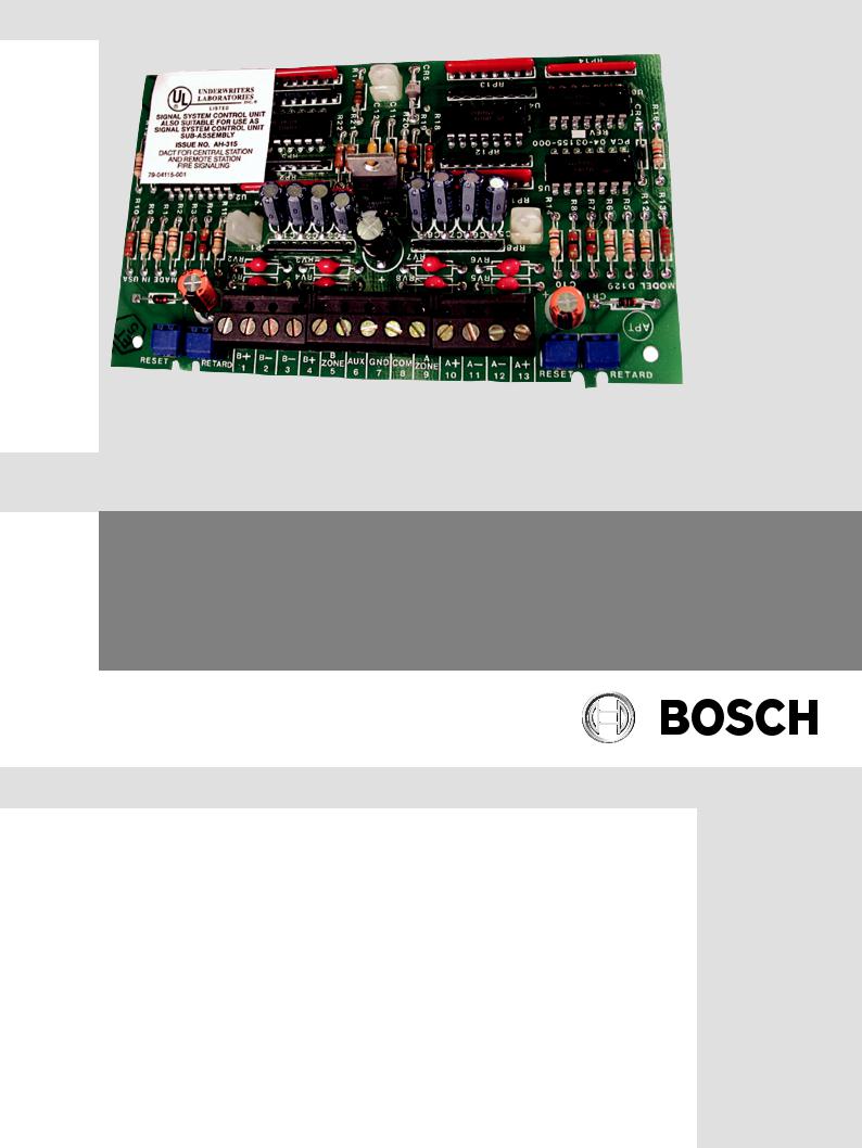
Bosch D129 Installation Manual

Dual Class A Initiating Circuit Module
D129
en Installation Instructions

Dual Class A Initiating Circuit Module |
Notices | en |
3 |
|
|
|
1 Notices
These instructions cover the installation of the D129 Dual Class A Initiating Circuit module as an interface to specified combined Burglary/Fire control panels for fire alarm and waterflow alarm applications.
Install, test and maintain the module according to these instructions, NFPA 72, local codes, and the authority having jurisdiction (AHJ). Failure to follow these instructions can result in failure of a detector to initiate an alarm event. Bosch Security Systems, Inc. is not responsible for improperly installed, tested or maintained devices.
Before installing the module, become familiar with the Installation and Operation Guide for the control panel you are using.
Warning!
!Follow these instructions to avoid personal injury and damage to equipment.
NFPA 72 requires that you perform a complete system wide functional test following any modifications, repair, upgrades or adjustments made to the system’s components, hardware, wiring, programming and software/firmware.
Bosch Security Systems, Inc. |
Installation Instructions |
2013.05 | 03 | F.01U.036.295 |

4 |
en | Notices |
Dual Class A Initiating Circuit Module |
|
|
|
2 Description
The D129 Dual Class A Initiating Circuit module is a fire system interface to the control panels listed in the table below for fire alarm and waterflow alarm applications. The module has two Class A (Style D) circuits, each with a screwdriver adjustable Alarm Retard and Alarm Reset Delay. Use the Alarm Reset Delay in waterflow applications. You can mount up to four modules inside the control panel enclosure.
The Class A (Style D) circuit is four wire data expansion loop with a feed and return for both the positive and negative sides of the loops. Unlike the two wire loops supervised by an end of line (EOL) resistor, the Class A circuits can detect an alarm condition with a single open or ground fault in the circuit.
The following table lists control panels compatible with the D129:
Control Panels |
See section: |
|
|
|
|
Active products: |
|
|
|
|
|
GV41, GV32, and GV23 panels |
Wiring, page 7 |
|
Legacy* |
|
|
|
|
|
D9412G, D7412G, D7212G**, D9412, D7412, |
See control panel’s documentation on the |
|
D7212** and D7212B1** panels |
Bosch website (http:// |
|
|
www.boschsecurity.com) |
|
D9112B1 and D9112 panels |
||
|
||
|
|
|
D8112 panel |
|
|
|
|
|
D7112 panel |
|
|
|
|
|
1 GV4 = D9412GV4, D7412GV4, and D7212GV4** panels |
||
2 GV3 = D9412GV3, D7412GV3, and D7212GV3** panels |
||
3 GV2 = D9412GV2, D7412GV2, and D7212GV2** panels |
||
* Legacy products were investigated to comply only to UL864 8th edition |
||
** indicates products which are not UL listed for commercial fire applications |
||
|
|
|
2013.05 | 03 | F.01U.036.295 |
Installation Instructions |
Bosch Security Systems, Inc. |
 Loading...