


D9142F |
24VDC Power Supply |
Operation and Installation
Table of Contents:
I. |
Description ................................................................................................................... |
2 |
||
II. |
Installation ........................................................................................................ |
3 |
||
|
A. |
Installing the D9142F .................................................................................... |
3 |
|
|
|
1. |
Mounting the Enclosure .......................................................................... |
3 |
|
|
2. |
Installing the D9142M .............................................................................. |
4 |
|
|
3. |
Installing the D1601 ................................................................................. |
4 |
|
B. |
Connecting AC Power .................................................................................. |
4 |
|
|
C. |
Batteries ....................................................................................................... |
7 |
|
|
|
1. |
Battery Connection ............................................................................... |
7 |
|
|
2. |
Battery Supervision .............................................................................. |
8 |
|
|
3. |
Stand-by Battery Calculations ............................................................. |
8 |
|
D. |
Connecting Auxiliary Devices ..................................................................... |
9 |
|
|
E. |
Power Supply Supervision .......................................................................... |
9 |
|
|
F. |
LED Indicators ............................................................................................ |
11 |
|
|
G. |
Switched Output Control ........................................................................... |
12 |
|
III. |
Specifications .................................................................................................... |
13 |
||
Description
The D9142F is a UL listed, Auxiliary Power Supply for use in Commercial Fire Alarm System applications. It provides up to 4 amps of power for charging batteries and powering auxiliary or indicating devices. The D9142F is provided in its own red enclosure that is louvered for ventilation. The green AC LED and the red Trouble LED are visible through the door. The enclosure also has room to install two 12 volt, 7 amp hour batteries. Power is supplied to the system via the D1601 Transformer. This specialized transformer provides power to both the D9142F and to the control/communicator.
The D9142F supervises all critical circuits of the power supply. It provides several installation and service outputs for troubleshooting. Five different trouble conditions can be recognized and optionally communicated to the central station. These trouble conditions are also annunciated by on board and off board LED indicators. A summary trouble relay can be programmed to give a general trouble indication.
Battery Lead Supervision is provided for both batteries when they are connected as described in the
Installing the Batteries section of this manual.
System Components
The D9142F Power Supply is shipped in three separate packages. The D9142M and installation instructions come in one package. The D8109L comes in a second package and the D1601 transformer comes in a third package.
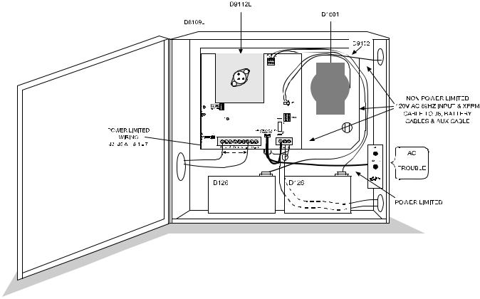
Figure 1: D9142F System
|
D9142F Operation and Installation |
|
|
|
|
F01U036364-03 |
Page 2 |
© Bosch Security Systems, Inc. |

Figure 2: D9142F Power Supply
You should have the following system components when you receive your D9142F Power Supply:
•One D1601 Transformer with Dual Secondary Winding
•One D8109L Louvered Enclosure with lock and key
•One D9142M Power Supply Assembly which includes the following:
•D9142LC Power Supply Board
•D9102 Mounting Skirt
•Operation and Installation Manual
•Yellow wiring harness, provides 16.5 VAC to panel
•Communicator harness, 5 conductor to panel
•Battery wiring harness with connector
Installation• Power and Trouble LED assembly
The D9142F typically is installed adjacent to the Control Communicator. It is compatible with all Bosch Security Systems, Inc. Control Panels but should only be used with a listed panel for fire alarm applications. For longer stand-by times, a second battery enclosure may be needed.
Mounting the Enclosure
The D8109L is a louvered version of the standard D8109, UL listed Fire Enclosure. It is supplied with the standard D101F lock and key set. The D8109L is designed to house the D9142F, the D1601 Transformer and the batteries. Standard sized knockouts are provided for conduit connections. Enclosures compatible with the D9142F: Only use the D8109L Enclosure with the D9142F Power Supply. This enclosure is designed to allow the air circulation needed to keep the power supply cool. The D9142F Power Supply’s enclosure requires 1/2 inch clearance on all sides.
|
D9142F Operation and Installation |
|
© Bosch Security Systems, Inc. |
Page 3 |
F01U036364-03 |
To attach the enclosure to the wall, use mounting hardware that is capable of supporting 55 pounds of equipment. You may need to mount a plywood sheet to the wall in order to support the weight of the power supply and batteries.
1. Position the enclosure on the surface so that is level. 2. Use the holes to mark the location for anchors.
3. Install anchors into the surface.
4. Using the three top anchor locations, drive the screws about 3/4 of the way in. 5. Hang the enclosure on the partially driven screws.
6. Secure the enclosure onto the surface with screws.
7. Adjust the enclosure so that it is again level and, while holding the enclosure in a level position, completely tighten the screws. Install screws in holes located toward the bottom of the enclosure.
8. Hang the D9142F onto the hangers at the top of the enclosure.
9. Drive a screw into the tab at the bottom center of the D9142F to secure the mounting skirt to the enclosure.
Installing the D9142M Power Supply Board
After mounting the D8109L enclosure, locate the D9142M and remove it from its packaging. In this box you should find three wiring harnesses. Save these harnesses. They will be used later in the installation.
•Battery Wiring Harness with connector
•Communicator Output Harness, 5 conductors
•Panel Power Harness, yellow wires, two conductors
The D9142M power supply mounts in the D8109L enclosure on the mounting tabs provided. Hook the skirt on the top two Connect power to the 120 VAC input terminals, following these steps:
1.Remove the knockout and install appropriate hardware for connection to conduit.
2.Remove the protective terminal cover marked CAUTION 120 VAC.
3.Pull the 120 VAC Power wires through the conduit hardware installed in the knockout.
4.Connect the wires as marked on the board.
5.Replace the protective cover over the 120 VAC Input terminals.
120 VAC Fuse
The 120 VAC fuse (F1) is located on the lower right-hand corner of the D9142F, above the 120 VAC terminals (see figure 3). Fuse F1 protects the D9142F and D1601 from damage due to power surges or over loads.
Fuse F1 is a type 3 AG, 4 Amp, 250VDC slow blow fuse. Radionics part number 57-01338-004. Danger: Turn off the 120 VAC circuit breaker before testing or replacing Fuse F1. Leaving the 120 VAC circuit breaker on can cause injury or death by electrocution.
If the green AC power LED is off, the 120 VAC circuit breaker is in the ON position, and the building lights and other electrical devices still operate, Fuse F1 may be open. To replace the fuse, follow these steps:
1.Turn OFF the 120 VAC dedicated circuit breaker.
2.Remove the protective cover from Fuse F1.
3.Pull the fuse from the socket.
4.Using a Volt/Ohm meter verify the 120 VAC has been removed and then test the resistance of the fuse. If the fuse is open, replace with a new fuse matching Fuse F1’s specification. If the fuse is closed, the problem may be elsewhere. Call a licensed electrician to troubleshoot any electrical problem.
5.Insert the fuse into the F1 socket.
6.Replace the protective cover.
7.Turn the 120 VAC circuit breaker ON.
|
D9142F Operation and Installation |
|
|
|
|
F01U036364-03 |
Page 4 |
© Bosch Security Systems, Inc. |
 Loading...