


Condens 2000 W
6 720 644 062-00.1O
Condens 2000 W
Service Manual
ZWB24 - 1AR...
TT-RH/PRMM21 - 01.2017

2 | Content
Content
1 Safety precautions and symbols 3
1.1 Safety precautions 3
1.2 Symbols 3
2 Service Function Adjustment 4
2.1 Service Function 4
2.2 Overview Service Function 4
2.2.1 1. Service Level 4
2.2.2 2. Service Level 5
3 Failures / Errors 6
3.1 Elimination of errrors 6
3.2 Failure / Error Codes Overview 7
3.3 Failure codes and corrections steps 8
3.4 Sensor (NTC) Values 24
3.4.1 Flow Temperature Sensor 24
3.4.2 Domestic Hot Water Temperature Sensor 24
3.4.3 Flue Gas Safety Temperature Sensor ( Behind
Burner) 24
3.5 Electrical Datas 25
3.6 Electrical Circuit Diagram 26
3.7 Structure 27
3.8 Function Diagram 29
4 Gas Values (CH and DHW) 30
Safety precautions and symbols | 3
1 Safety precautions and symbols
1.1 Safety precautions
If you smell gas
B Turn off gas service cook.
B Open windows.
B Do not operate any electrical switches.
B Extinguish any naked flames.
B Leave the building and telephone the gas company and
authorized dealer from an outside phone.
If you smell fumes from the appliance
B Switch off the appliance.
B Open windows and doors.
B Inform your heating engineer.
Fitting and Modifications
B Fitting of the appliance or many modifications to be appli-
ance may only be carried out by a compotent perEND.
B Flue systens must not be modified in any way.
B If the appliance has a type B.. flue system : Ventilation
openings in doors, windows and walls must not be sealed
or restricted. If draught-proof windows are installed, measures must be taken to ensure there is an adequate supply
of air to the appliance for combustion.
Inspection / Maintenance
B We recommend take out a to have the system regulary
serviced in order to ensure that it functions reliably and
safely.
B Only use original spare parts.
Combustible materials
B Do not store or use any combustible materials (paper, thin-
ners, paints etc.) in the vicinty of the appliance.
Combustion Air / Ambient Air
B Keep combustion air/ambient air free of corrosive sub-
stances (e. g. halogenated hydrocarbons which contain
chlorine or fluorine compounds). In this way corrosion can
be prevented.
Instructions to the customer
B Explain to the customer how the appliance works and how
to operate it.
B Advise the customer that he / she must not make any mod-
ifications to the appliance or carry out any repairs on it.
1.2 Symbols
Signal words indicate the seriousness of the hazard in terms
of the consequences of not following the safety instructions.
• Caution indicates that minor damage to property could
result.
• Warning indicates that minor personal injury or serious
damage to property could result.
• Danger indicates that serious personal injury could result.
In particularly serious cases, lives could be at risk.
Notes contain important information in cases where there is
no risk of personal injury or damage to property.
Safety instructions in this document are identified by a warning-triangle symbol and are printed on a grey background.
Notes are identified by the symbol shown on
the left. They are bordered by horizontal lines
above and below the text.
4 | Service Function Adjustment
2 Service Function Adjustment
2.1 Service Function
Service functions are in divided in 2 level :
• 1. Level (see page 4)
• 2. Level (see page 5)
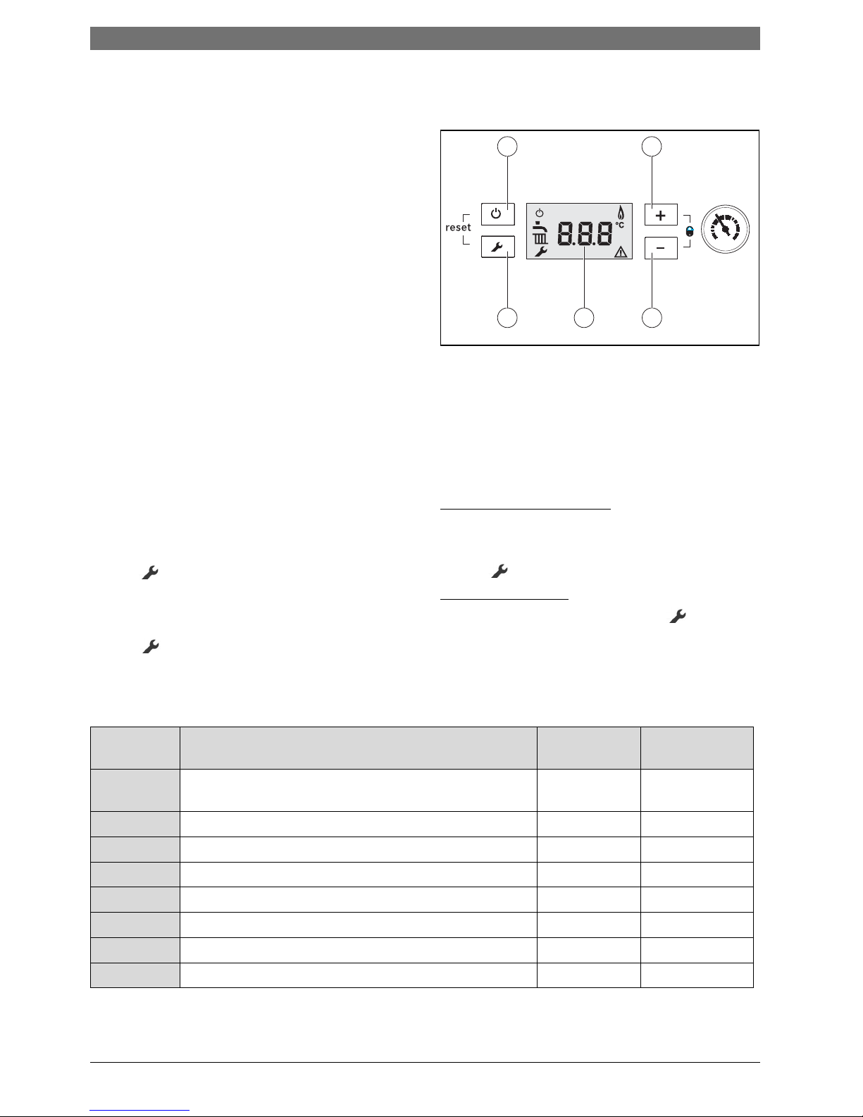
Fig. 1
1 Stand by (On/off) Button
2 „Up (+)“ Button
3 „Down (-)“ Button
4 Temparature Display (°C)
5 Service Button
2.2 Overview Service Function
2.2.1 1. Service Level
Operation
Change or query of a service function :
B Press button for 5 second. The service function will be
shown on Display (e.g. 1.2.C).
B Select the desired/requested service code with “+” or “-”
button.
B Press button again (for entering).
After that you will see the selected (default) value on Display.
Changing / Adjustment of Value:
B Change the values with “+” or “-” button.
Storage/Save of Value :
B Press button until [ ] symbol will be shown on Display.
Exit from Service Level :
B For the exit from service level press the or Stand by
button.
The flow temperature will be shown again on display.
1. Level
1
0
2
3
4
bar
45
2
3
1
6 720 644 501-07.1O
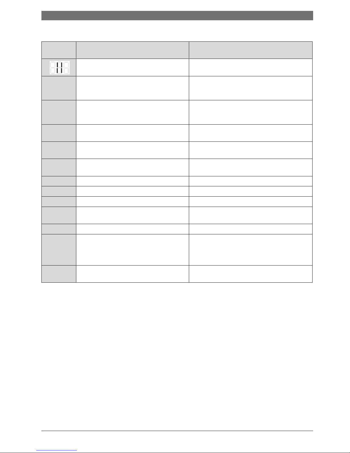
Service Code Description Range
Initial (Factory
setting)
1.2.C Automatical Air Purging (0 = offý, 1= active ) Total time : 2 min.
and 20 sec on/off intervall
0 - 1 0
1.2.F Operating Mode : (0 = Normal, 3= min. output, 4 = max. output) 0, 3 , 4 0
1.3.b Burner Anticycling 1 - 10 min. 3 min.
1.3.C Burner start hysterisis (for flow temp. NTC) 0 - 10 K 5 K
1.5.b Fan overrun 1 - 18 (x10) sec. 3 (=30 sec.)
1.6.A Last failure on memory 00 - FF -
1.6.d Display actual water flow rate by turbine ( l/min. ) 0 - 99
1.7.A Operating LED (1 = on, 0 = 30 off after 30 sec.) 0 - 1 1
Tab. 1 1. level service functions
Service Function Adjustment | 5
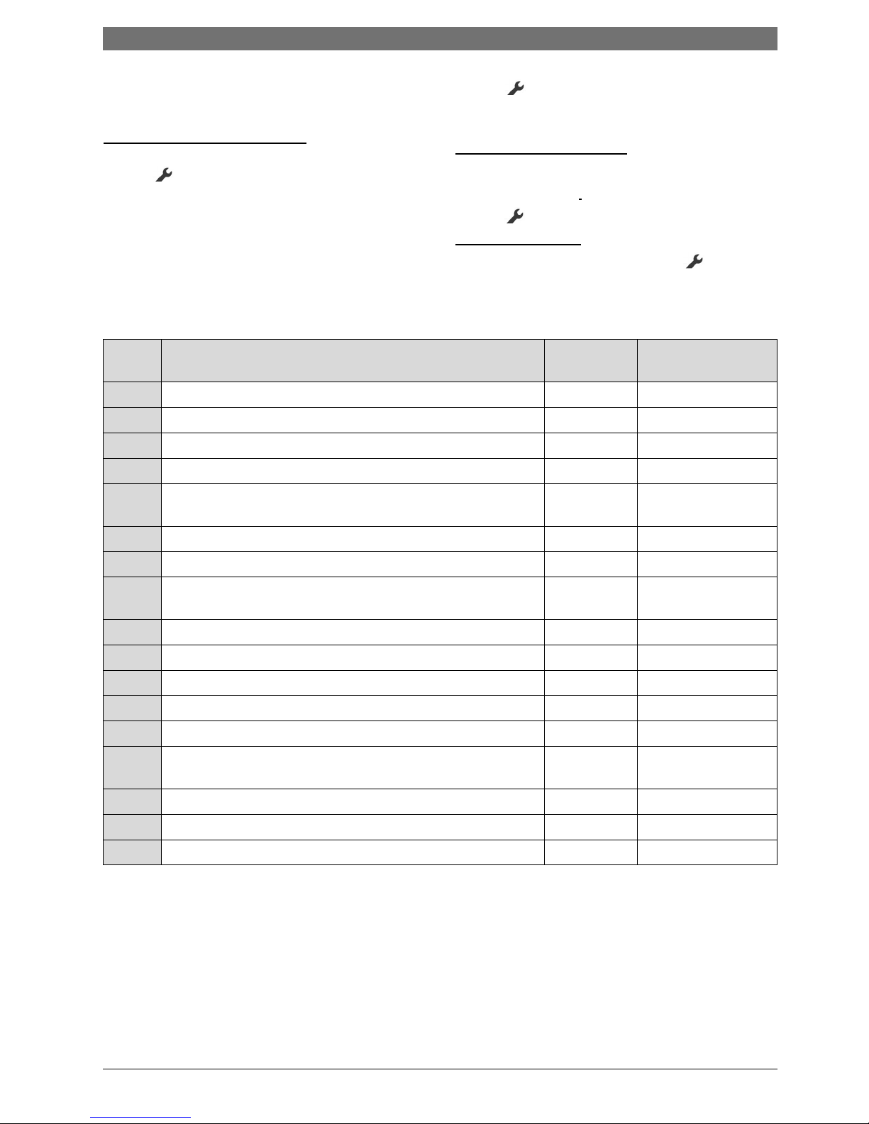
2.2.2 2. Service Level
Operating
Change or query of a service function
:
B To enter to 2. service level must be entered first in 1. level.
Press button for 5 second. The service function onf1.
level will be shown on Display (e.g. 1.2.C).
B To enter to 2. level : Press both “+” and “-” buttons for 3
second. The service function of 2. level will be shown on
Display (e.g. 2.1.A).
B Select the desired/requested service code with “+” or “-”
button.
B Press button again (for entering)..
After that you will see the selected (default) value on Display.
Changing / Adjustment of Value:
B Change the values with “+” or “-” button.
Storage/Save of Value :
B Press button until [ ] symbol will be shown on Display.
Exit from Service level :
B For the exit from service level press the or Stand by
button.
The flow temperature will be shown again on display.
2. Level
Service
Code
Description Range Initial (Factory Setting)
2.1.A CH max. heat output 30 - 100 % 100 %
2.1.b DHW max. heat ou tput (in winter mode) 30 - 100 % 100 %
2.2.b CH max flow temperature 35 - 82°C 82°C
2.3.d CH min. heat output 30 - 100 % 30 %
2.3.F Delay time after DHW in winter mode (Heating mode is disabled for this
period of time)
0 - 5 min. 1 min.
2.8.A Software version number e.g.. 162 112 -
2.8.E Reset to factory (default) setting 0 0
2.9.A Operation mode permanent : (0 = Normal, 1= min. power, 2 = max.
power)
0 - 2 0
2.9.E Delay time for the turbine ( each unit = 0,5 sec.) 1 - 6 2
2.9.F Pump over run) (CH circuit) 0 - 10 min. 3
2.A.A Actual flow temperature ºC -
2.A.b Actual DHW temperatur ºC -
2.A.F Actual combustion chamber temperature ºC -
2.b.d Selection of flue length (MAP Value) (0 = off, 1 - 10 : fan speed accord-
ing flue pipe length, see flue manuel for details)
0 - 10 0
2.b.F Solar mode delay time (sec.) 1 - 50 1
2.c.F Pump "over run” (DHW mode) 0 - 30 sec. 5 sec.
2.0.A Gas Convertion (0 = NG, 1 = LPG) 0 -1 0
Tab. 2 2. level service functions
6 | Failures / Errors
3 Failures / Errors
3.1 Elimination of errrors
All regulation, control and safety equipment of appliance is
controlled by the control unit.
B If any failure during operation occurs, symbol and
maybe will start to flash also. In additional the failure
code will be shown on display (e.g. EA).
B If and symbol on display flash:
B For the reset : Press and Stand by button until and
symbol expire on display.
The appliance will start up again and the flow temperature
will be displayed.
B If only symbol flashes:
B Switch the appliance first off and then on again by means
of the standby key.
The appliance will start up again and the flow temperature
will be displayed.
If a failure can not be eliminated :
B Contact your approved installer or Customer Service for
assistance, providing details of the fault and the appliance.
Danger: Explosion !
B Turn off gas cock before working on gas-
bearing components.
B Check for leaks before working on gasbear-
ing components.
Danger: Poisoning !
B Check for leaks before working on gasbear-
ing components.
Danger: Risk of electric shock !
B Always disconnect the power supply to the
appliance at the mains before carrying out
any work on the electrical systems and components (fuse, circuit breaker).
Leaking water may damage the Cotronic module.
B Cover the Cotronic module before working
on any parts that carry water.
For an overview of faults, see page 7.
Failures / Errors | 7
3.2 Failure / Error Codes Overview
Failure Code
on Display
Failure Descripton Steps
MAP not selected (Fan speed adjustment according the flue pipe length).
Check the adjustment /selection via service function
2.b.d).
A2 Combustion chamber NTC failure (behind burner) :
when the temperature by CC NTC reached to limit
Check the and the heat exchanger surface, whether is
blocked or not. And check the sensor and the connections.
A6
1)
1) Failure codes is adapted to the EMS (>FD660)
Combustion chamber NTC failure (behind burner) :
when NTC not detected or open circuit
Check the and the heat exchanger surface, whether is
blocked or not. And check the sensor and the connections.
A7 Domestic hot water temperature sensor not correct
installed or failure.
Check the sensor and cable connection.
B3 --> d5
2)
2) Failure codes is adapted to the EMS (>FD660)
Short circuit / failure in water level switch. Check the condensate water drain and recuperator
(condens-heatexchanger).
CE --> d4
3)
3) Failure codes is adapted to the EMS (>FD660)
Gradient limit : Temperature rises too rapidly in
heating mode.
Check the pump, system pressure and by-pass circuit.
C7 Fan sensor not detected. Check the fan.
C8 Fan speed can not reached to target speed. Check the fan fo r the blockage and the electrical supply.
d7 Modu lator coil failure (regulator valve on gas valve) Check the cable connectio n.
EA Ignition lock-out (flame not detected) (pump is run-
ning).
Check the gas cock, gas pressure, electrode and the
cable connection.
E2 Flow temperature sensor failure (pump is running). Check the flow temperature sensor and the connection.
E9 Overheat lock-out by temperatur limiters (STBs)
(Flue gas + prim. Heatexchanger). In this case ;
Heat demands is blocked and pump stops 3 min.
later.
Check the system presseure, temperature sensor, pump
and fuses on board. Discharge the air in system. Check
also the flue gas pipe and heatexchanger.
FA Safety valve leaks. Check the gas valve, the cable connection and electrode
set.
Tab. 3 Failure codes
8 | Failures / Errors
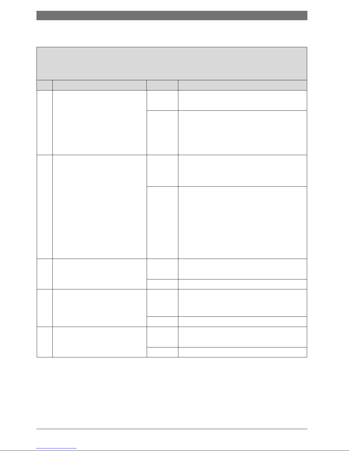
3.3 Failure codes and corrections steps
A2 and operating LED is flashing.
Combustion chamber NTC failure (behind burner) : when the temperature by CC NTC reached to limit 1)
Control Step Action
1. Check if combustion chamber NTC damaged or not and the position.
B Switch off the appliance.
B Pull the NTC cables out.
B Measure NTC resistance.
Are the values correct ? (see NTC values)
yes: B Check the cable connection.
A2 failure still exist ? -->2.
no: B Change the NTC.
B Connect the cable.
B Switch on the appliance.
A2 failure still exist ? -->2.
2. Check if cable damaged or not.
B Switch off the appliance.
B In case of NTC is cahnged :
- Pull the NTC cables out.
- Measure NTC resistance.
- Reconnect the NTC cable.
B Pull out the 20 poled connector on
control unit.
B Measure the NTC resistance directly
on 20 poled connector. Are the measured values on NTC and cocnector different ?
yes: B Change the cable harness.
B Switch on the appliance.
A2 failure still exist ? -->3.
no: -->3.
3. Is there any blockage on flue gas pipe? yes: B Remove the blockage.
A2 failure still exist ? -->4.
no: -->4.
4. Is the correct MAP (fan speed) value
according flue gas pipe length choosen ?
no: B Adjust correct MAP value according flue gas pipe
length and diameter. See capitel 7.2.
A2 failure still exist ? -->5.
yes: -->5.
5. Is fan running correct ? no: B Change the fan.
A2 failure still exist ? -->6.
yes: -->6.
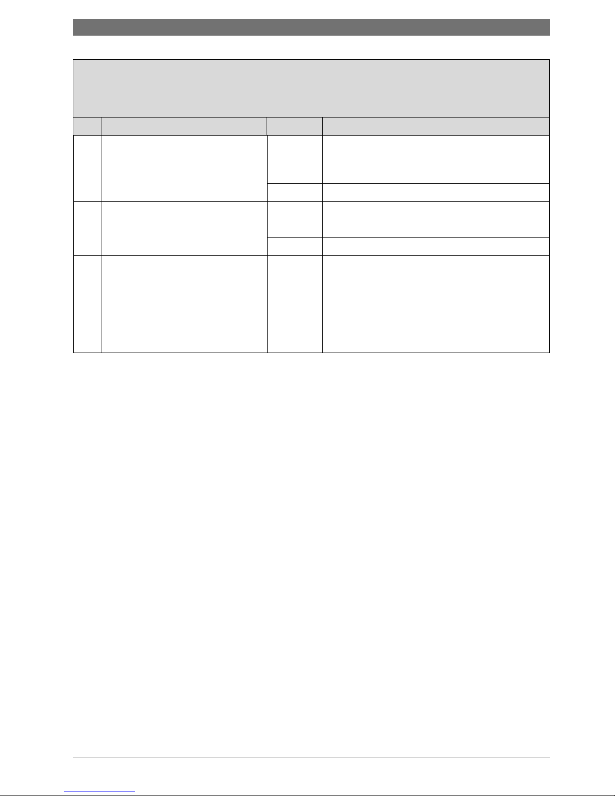
Failures / Errors | 9
6. Check the burner gas pressure. Are the
values OK ?
yes: B Correct the gas pressure values. If not possible,
change the gas valve.
A2 failure still exist ? -->7.
no: -->7.
7. Is the heat exchanger and recuperator
surface dirty or damaged (blockage) ?
yes: B Remove the blockage.
A2 failure still exist ? -->8.
no: -->8.
8. Electronic card is defect. B Switch off the appliance.
B Cut mains supply.
B Change the electronic card.
B Connect to main supply.
B Switch on the appliance.
1)
The sensor is activated after 1 minute. After 3. failure the boiler is blocked. By first 2. time it will be reseted automaticly after 15 min.
A2 and operating LED is flashing.
Combustion chamber NTC failure (behind burner) : when the temperature by CC NTC reached to limit 1)
Control Step Action
10 | Failures / Errors
A6 and operating LED is flashing.
Combustion chamber NTC failure (behind burner) : when NTC not de tected or open circuit
Control Step Action
1. Check if combustion chamber NTC damaged or not and the position.
B Switch off the appliance.
B Pull the NTC cables out.
B Measure NTC resistance.
Are the values correct ? (see NTC values)
yes: B Check the cable connection.
A6 failure still exist ? -->2.
no: B Change the NTC.
B Connect the cable.
B Switch on the appliance.
A6 failure still exist ? -->2.
2. Check if cable damaged or not.
B Switch off the appliance.
B In case of NTC is cahnged :
- Pull the NTC cables out.
- Measure NTC resistance.
- Reconnect the NTC cable.
B Pull out the 20 poled connector on
control unit.
B Measure the NTC resistance directly
on 20 poled connector. Are the measured values on NTC and cocnector different ?
yes: B Change the cable harness.
B Switch on the appliance.
A6 failure still exist ? -->3.
no: -->3.
3. Electronic card is defect. B Switch off the appliance.
B Cut mains supply.
B Change the electronic card.
B Connect to main supply.
B Switch on the appliance.
 Loading...