


D7212GV3-C1255
D9412GV3/D7412GV3/D7212GV3
Control Panels UL Installation Instructions
en Installation Guide

D9412GV3/D7412GV3/D7212GV3 Table of Contents | en 3
Table of Contents
1 Installation 4
1.1 Installation Preparation 4
1.2 Enclosure Options 4
1.3 Mounting Enclosure 4
1.4 Installing the Control Panel 5
1.5 Connecting Earth Ground 5
1.5.1 Terminal 10 5
1.5.2 Ground Fault Detect Enable 6
1.5.3 Enabling Ground Fault Detection 6
1.5.4 D7212GV3 Ground Fault Specifications 7
1.5.5 Locking the Reset Pin 7
2Diagrams 8
2.1 Faceplates 8
2.2 Power Supply Side Wiring Diagrams 9
2.2.1 D9412GV3/D7412GV3 Power Supply Side Wiring Diagram (D9412GV3 shown) 9
2.2.2 D7212GV3 Power Supply Side Wiring Diagram 10
2.3 Input Points and Peripheral Devices Wiring Diagram (D9412GV3 shown) 11
2.4 SDI Devices Wiring Diagrams 12
2.4.1 D9412GV3 SDI Devices Wiring Diagram 12
2.4.2 D7412GV3 SDI Devices Wiring Diagram 13
2.4.3 D7212GV3 SDI Devices Wiring Diagram 14
2.5 Keyswitch Wiring 15
3 Power Supply and Power Outputs 16
3.1 Power Supply - Primary 16
3.1.1 Primary (AC) Power Circuit 16
3.1.2 Installing the Transformer 16
3.2 Power Terminals - Secondary 17
3.2.1 Secondary (DC) Power 17
3.2.2 Installing the Battery 17
3.3 Power Outputs - Circuit Protection 18
3.4 Power Outputs - Total Available Power 19
3.5 Power Outputs - Continuous Power Output Terminals 3, 8, 24, and 32 19
3.6 Power Outputs - Programmable Power Output Terminals 6, 7, and 8 19
3.6.1 Programming 19
3.6.2 Terminals 6 and 7 20
3.6.3 Fire System Power Formula 20
3.6.4 Terminal 8 20
4 Specifications 21
4.1 Terminal Wiring Requirements 22
4.2 Circuit Classes 23
Bosch Security Systems, Inc. Installation Guide F.01U.162.539 | 01 | 2010.02
4 en | Installation D9412GV3/D7412GV3/D7212GV3
1 Installation
1.1 Installation Preparation
This section contains a general installation procedure and refers to other sections of the
document for detailed instructions. Review this document and the D9412GV3/D7412GV3
Program Entry Guide (P/N: F01U143071) or D7212GV3 Program Entry Guide (P/N:
F01U143077) before beginning the installation to determine the hardware and wiring
requirements for the features used. Have the following documentation available when reading
through this guide:
– D9412GV3/D7412GV3 Program Record Sheet (P/N: F01U143072) or D7212GV3 Program
Record Sheet (P/N: F01U143078)
– Security System Owner's Manual (P/N: 71-06633-000) and GV3 Series Owner's Manual
Supplement (P/N: F01U143082)
– Installation manual for keypad or annunciator (D1255 all models, D1255RB, D1256,
D1256RB, D1257, D1257RB, D1260 all models, or D720 all models)
1.2 Enclosure Options
Mount the control panel assembly in any of the Bosch Security Systems, Inc. enclosures
listed:
– D8103 Universal Enclosure (tan)
– D8109 Fire Enclosure (red) for the D9412GV3 and D7412GV3 Control Panels
– D8108A Attack Resistant Enclosure (tan)
Refer to the D9412GV3/D7412GV3 Approved Applications Compliance Guide (P/N:
F01U143069) or D7212GV3 Approved Applications Compliance Guide (P/N: F01U143080) to
determine if the application requires a specific enclosure.
1.3 Mounting Enclosure
1. Run the necessary wiring throughout the premises.
2. Mount the enclosure in the desired location. Use all five enclosure mounting holes. Refer
to Figure 1.1, Page 5.
3. Pull the wires into the enclosure.
NOTICE!
Electromagnetic interference (EMI) can cause problems on long wire runs.
F.01U.162.539 | 01 | 2010.02 Installation Guide Bosch Security Systems, Inc.
D9412GV3/D7412GV3/D7212GV3 Installation | en 5
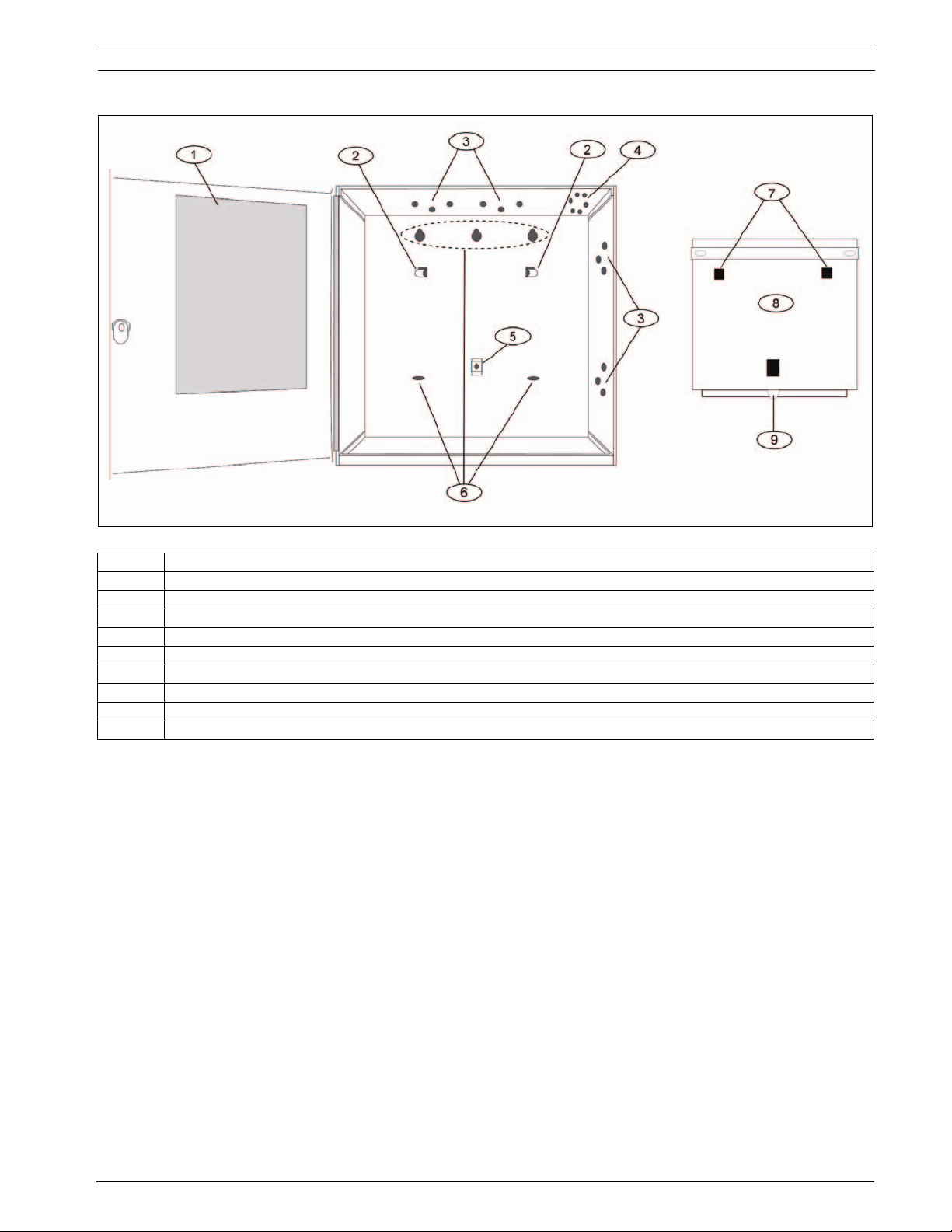
Figure 1.1 Enclosure Mounting
Callout Description
1 Point chart label
2 Mounting skirt hooks (2)
3 Module mounting holes (12)
4 Tamper switch mounting holes (5)
5 Skirt mounting hole (1)
6 Enclosure mounting holes (5)
7 Mounting skirt hook holes (2)
8 Back of the control panel
9 Lock down tab
1.4 Installing the Control Panel
1. Place the control panel over the inside back of the enclosure, aligning the large
rectangular openings of the mounting skirt with the mounting hooks of the enclosure.
Slide the control panel down so that it hangs on the hooks. Refer to Figure 1.1, Page 5.
2. Remove the tape from the #6 x 1/4-in. screw in the mounting tab on the control panel.
The screw passes through the mounting tab and into the skirt mounting hole in the
enclosure. Tighten the screw to secure the control panel in the enclosure.
3. Connect earth ground to the control panel before making any other connections. Refer to
Section 1.5 Connecting Earth Ground, page 5.
1.5 Connecting Earth Ground
1.5.1 Terminal 10
To help prevent damage from electrostatic charges or other transient electrical surges,
connect the system to earth ground at Terminal 10 before making other connections.
Recommended earth ground references are a grounding rod or a cold water pipe.
Bosch Security Systems, Inc. Installation Guide F.01U.162.539 | 01 | 2010.02

6 en | Installation D9412GV3/D7412GV3/D7212GV3
WARNING!
Do not use telephone or electrical ground for the earth ground connection. Use 1.8 mm (14
AWG) to 1.5 mm (16 AWG) wire when making the connection. Do not connect other control
panel terminals to earth ground.
1.5.2 Ground Fault Detect Enable
NOTICE!
To meet UL 864 requirements, enable Ground Fault Detect.
A ground fault is a circuit impedance to earth ground. The control panel has a ground fault
detection circuit that, when enabled, detects ground faults on Terminals 1 to 9 and 11 to 32.
The control panel also detects and annunciates ground faults on any device connected to it.
If a ground fault condition occurs, the keypads display SERVC GND FAULT and the control
panel sends a GROUND FAULT TROUBLE, AREA 1. When the control panel recognizes that the
ground fault condition is corrected, and remains corrected for between 5 to 45 consecutive
seconds, a Restoral Report is sent.
NOTICE!
The D9412GV3/D7412GV3/D7212GV3 Control Panels log and print a Ground Fault event as a
Trouble Point 256 if communicating in Modem IIIa
format, the D7212GV3 generates a Ground Fault (310) event.
2
format. If communicating in Contact ID
1.5.3 Enabling Ground Fault Detection
To enable the Ground Fault Detect Enable feature, lock (close) the S4 Ground Fault Detect
Pin on the control panel (refer to Figure 1.2, Page 6).
Figure 1.2 Ground Fault Detect (S4)
Callout Description
1 S4 Locked (Closed). Control panels detects ground faults.
2 S4 Unlocked (Open). Control panel does not detect ground faults.
F.01U.162.539 | 01 | 2010.02 Installation Guide Bosch Security Systems, Inc.
D9412GV3/D7412GV3/D7212GV3 Installation | en 7
1.5.4 D7212GV3 Ground Fault Specifications
Table 1.1, Page 7 provides the impedance specifications for detecting ground faults when any
terminal or field wiring is shorted to ground.
Impedance Control Panel Detects Ground Fault
≤ 300 Ω
Yes
300 Ω to 200 k Ω Detection depends upon the terminal
≥ 200 k Ω
Tab le 1.1 Ground Fault Impedance Specifications
No
1.5.5 Locking the Reset Pin
Locking the reset pin disables the control panel (refer to Figure 1.3, Page 7). When the control
panel is disabled, the system ignores the keypads and points. CALL FOR SERVICE appears in
keypad displays when the pin is locked down.
On-board relays (Terminals 6 and 7) and off-board relays deactivate when the control panel is
reset. Terminal 8 has power when the relay is deactivated. Activation interrupts power at that
terminal. The on-board relay (Terminal 8) remains deactivated when the reset pin is locked in
the disable position.
Releasing the reset pin from the closed position resets the control panel. The control panel
resets all its timers, counters, indexes, and buffers. Any points that restore after a reset do
not generate Restoral Reports.
If the reset pin is placed in the disable position when all areas are armed, there must be an
entry in the Answer Armed program item. Refer to RPS Parameters in the D9412GV3/
D7412GV3 Program Entry Guide (P/N: F01U143071) or the D7212GV3 Program Entry Guide (P/
N: F01U143077).
Locking the pin in the disable position applies power to the control panel and charges the
battery while the detection devices and keypads are installed.
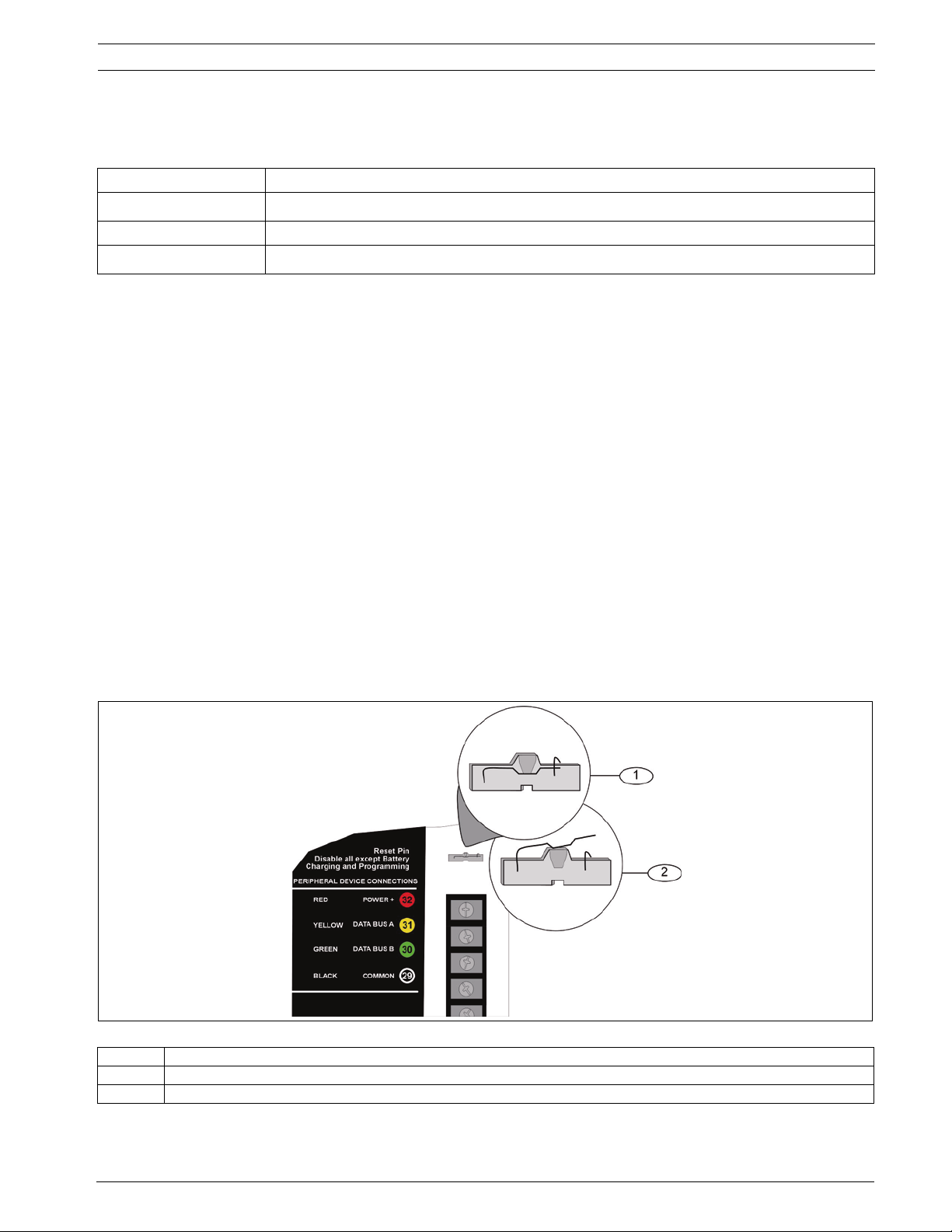
Figure 1.3 Reset Pin
Callout Description
1 Reset pin locked (closed)
2 Reset pin normal (open)
Bosch Security Systems, Inc. Installation Guide F.01U.162.539 | 01 | 2010.02
8 en | Diagrams D9412GV3/D7412GV3/D7212GV3
2 Diagrams
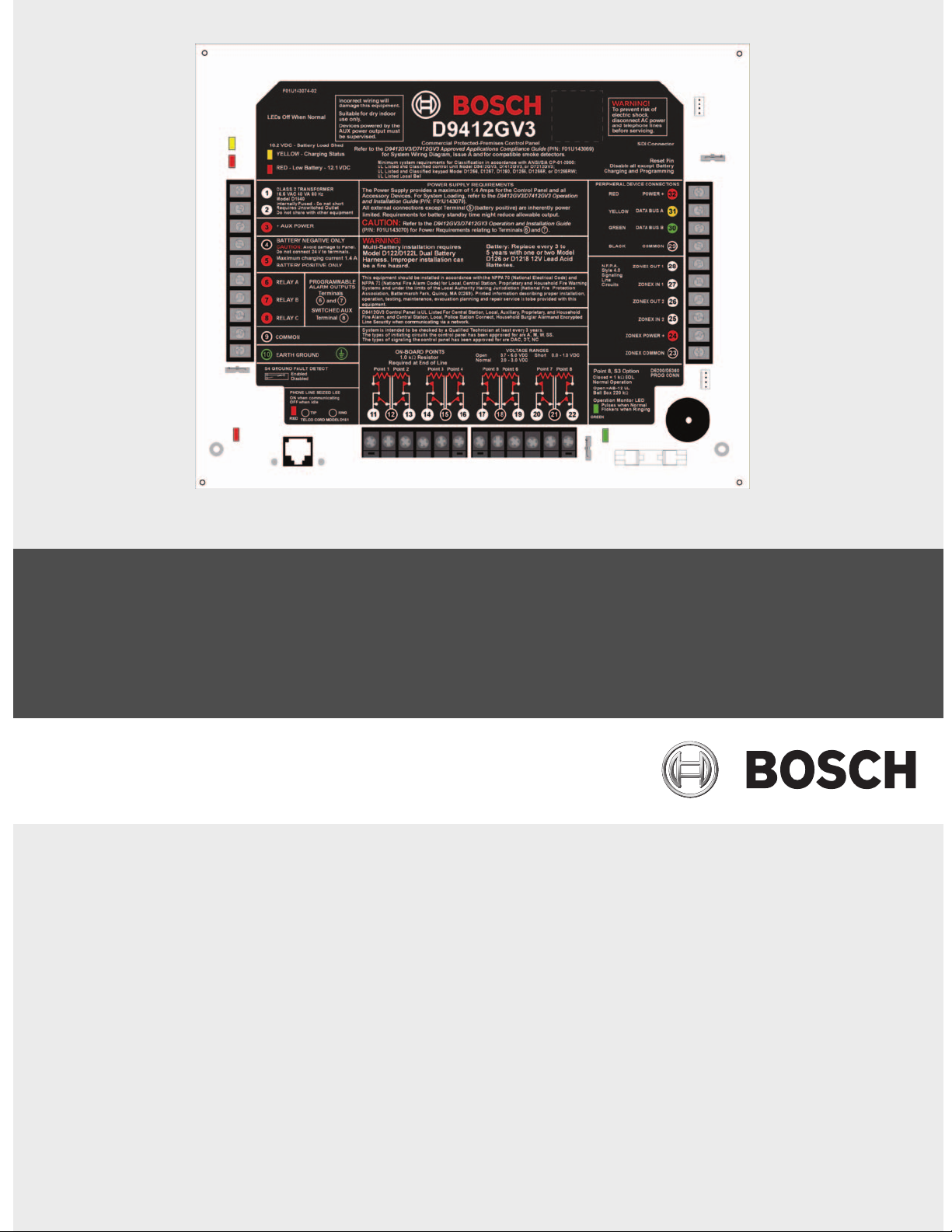
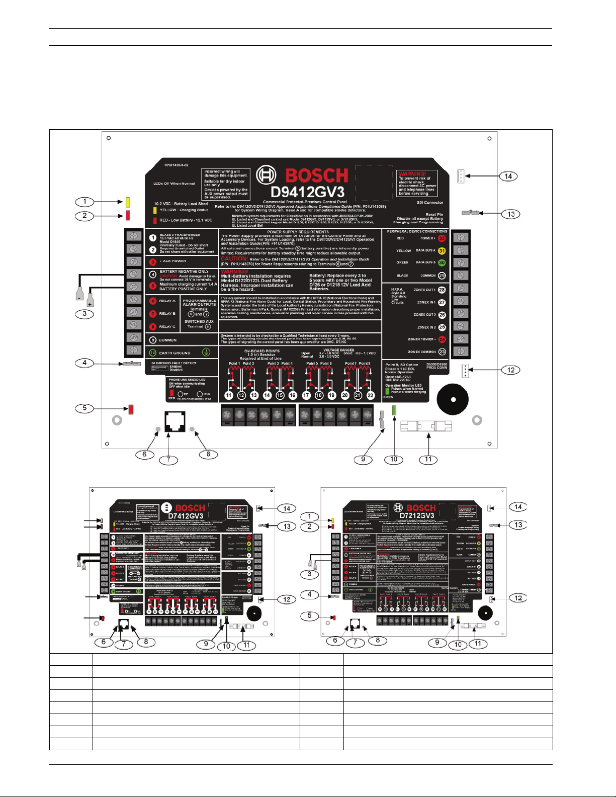
2.1 Faceplates
Callout Description Callout Description
1 Charging status LED (yellow) 8 Ring
2 Low battery LED (red) 9 S3, Point 8 EOL selection
3 Color-coded battery leads 10 Operation monitor LED (green)
4 Ground fault detect enable 11 Accessory connector
5 Phone LED (red) 12 Programming connector
6 Tip 13 Reset pin
7 Telephone cord connector 14 SDI quick connector
F.01U.162.539 | 01 | 2010.02 Installation Guide Bosch Security Systems, Inc.
D9412GV3/D7412GV3/D7212GV3 Diagrams | en 9
2.2 Power Supply Side Wiring Diagrams
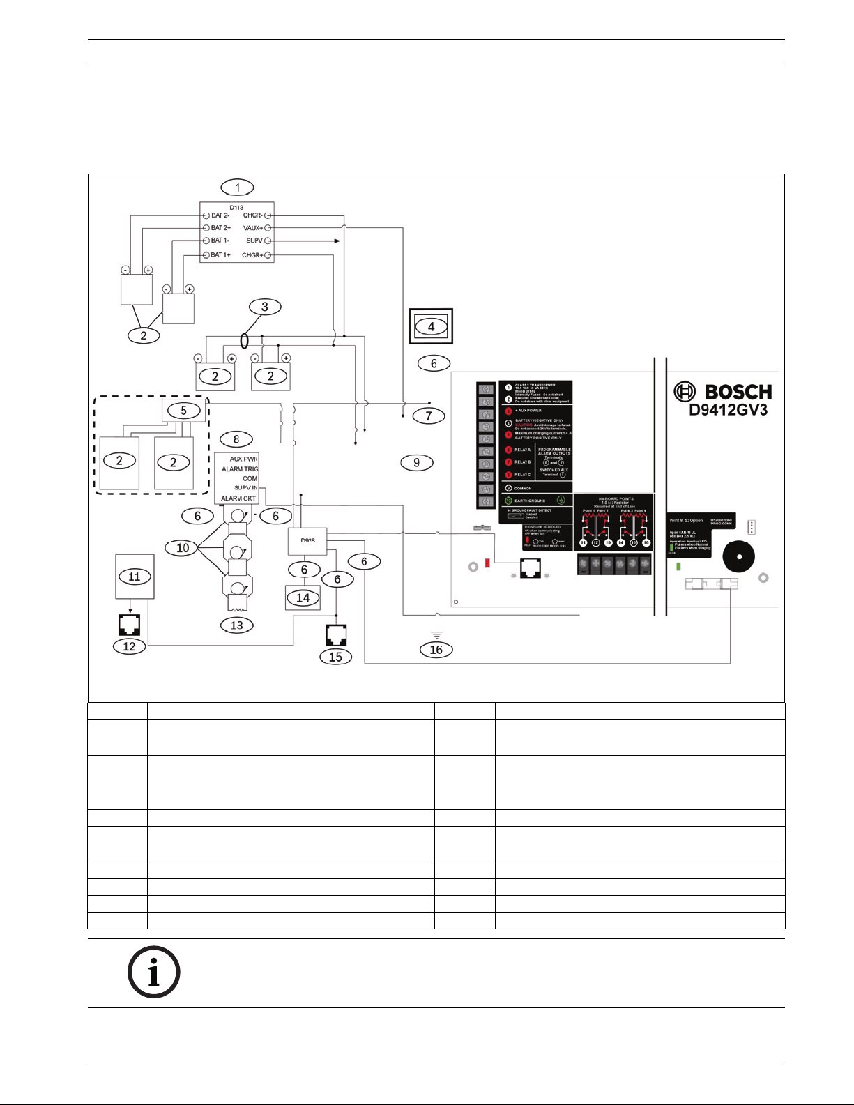
2.2.1 D9412GV3/D7412GV3 Power Supply Side Wiring Diagram
(D9412GV3 shown)
Callout Description Callout Description
1 If required by local AHJ, connect D113 Battery
Lead Supervision Module.
2 Batteries 10 Listed Audible Signaling Devices rated at
3 D122 Dual Battery Harness, as required 11 C900V2 or C900TTL-E (optional)
4 D1640 Transformer and D8004 Transformer
Enclosure required for NFPA Applications
5 Phone LED (red) 13 560 W, 2 W EOL Resistor (P/N: 15-03130-005)
6 Power limited, supervised 14 RJ31X, primary phone line
7 Power limited 15 D928
8 D192G Bell Supervision Module 16 To earth ground
NOTICE!
All external connections except Terminal 5 (battery positive) are power limited.
Bosch Security Systems, Inc. Installation Guide F.01U.162.539 | 01 | 2010.02
9 To Relay A or Relay B
12.0 VDC nominal (do not use vibrating type
horns)
12 RJ31X, secondary phone line
 Loading...