


Bosch D263, D263TH, D273, D273IS, D273TH Installation Manual
...D263/D273 Series
Installation Instructions
Photoelectric Smoke
EN Detector
D263/D273 Series | Installation Instructions | 1.0 |
Overview |
|
|
Notice
Install, test, and maintain the D263/D273 Series according to these instructions, NFPA 72, Local Codes and the authority having jurisdiction (AHJ). Failure to follow these instructions can result in the detectors not operating properly.
Bosch is not responsible for improperly installed, tested, or maintained devices.
Follow the procedures in these instructions to avoid personal injury or damage to equipment.
NFPA 72 requires performing a complete system-wide functional test following modifications, repairs, upgrades, or adjustments to the system’s components, hardware, wiring, programming, software, and firmware.
FCC Compliance
This device complies with Part 15 of the FCC Rules and the RSS-210 of Industry and Science Canada.
Operation is subject to the following two conditions:
1.this device may not cause harmful interference, and
2.this device must accept any interference received, including interference that may cause undesirable operation.
Changes or modifications not expressly approved by Bosch Security Systems can void the user’s authority to operate the equipment.
1.0 Overview
These instructions cover the D263/D273 Series Photoelectric Smoke Detector installations in a fire system supervised by a Bosch fire alarm control panel (FACP).
The D263/D273 Series are UL Listed, open-area detectors designed for use with commercial fire protective signaling and household fire warning systems (refer to NFPA 72).
For commercial and industrial installations, space the detectors 30 ft (9.2 m) apart as recommended by NFPA 72.
An LED indicator flashes approximately every 3.5 sec to verify the detector has power and the smoke sampling circuitry is functioning. The LED latches ON during an alarm, allowing the user to easily verify individual detector alarms. After you clear the alarm condition, reset the detector by interrupting power.
The LED on the D273IS latches on during an alarm from heat but not from smoke.
Power supervision requires an optional end-of-line (EOL) power supervision device such as a D275, on the D273 Models without EOL relay, and an EOL resistor as specified by the control panel manufacturer. The D273ES, D273THE and D273THES have a built in EOL supervision relay and can be used as an equivalent to the D275.
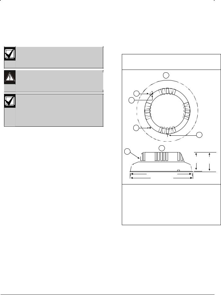
Figure 1: |
D263/D273 Series Detector Top and |
||
|
|
Side Views |
|
|
|
1 |
|
|
2 |
|
|
|
3 |
|
|
|
4 |
|
|
|
|
5 |
|
7 |
|
6 |
|
|
|
|
|
|
|
2 in. |
2.1 in. |
|
|
(5 cm) |
(5.4 cm) |
|
|
5 in. (12.7 cm) |
|
|
|
5.2 in. (13.4 cm) |
|
1 - |
Top view |
|
|
2 - Calibration voltage pins |
|
||
3 - |
Cover latch |
|
|
4 - Alarm and Test LED |
|
||
5 - Magnet Test locator |
|
||
6 - |
Side view |
|
|
7 |
Dust cover |
|
|
2.0 Mounting
1.Remove the dust cover. The dust cover can be replaced during construction periods, but it must be removed after the alarm system is enabled.
2.Remove the detector from the mounting plate by pressing the locking tab and twisting it counterclockwise. If you do not want the locking tab, break if off now (refer to Figure 2).
3.Install the mounting plate, insert the wiring, and pull the wiring through the wire entrance.
2 |
Bosch Security Systems, Inc. | 02/06 | 31341J |

D263/D273 Series | Installation Instructions | 3.0 |
Wiring |
|
|
Figure 2: Mounting a D263/D273 Series
Detector
1
2
3
1 - Wire entrance
2 - Locking tab
3 - Mounting holes
3.0 Wiring
Before connecting or disconnecting any D263/D273 Series Detectors, remove all AC and battery power from the FACP. Failure to do so can result in personal injury and damage to the equipment.
The terminal block is removable. It might be easier to remove the terminal block from the detector before making the wire connections. Remove the terminal block by pulling it back and then pulling up. Refer to Figures 3 through 8 on pages 3 through 5 for wiring details.
When all wiring connections are made, connect the detector to the mounting plate by twisting it clockwise into place.
Refer to your control panel’s installation instructions for EOL resistor selection.
Figure 3: D263 Series/D263TH Wiring |
||||||||
|
– |
– |
+ |
+ |
– |
– |
+ |
+ |
|
IN |
OUT |
IN |
OUT |
IN |
OUT |
IN |
OUT |
|
1 |
2 |
3 |
4 |
1 |
2 |
3 |
4 |
1 |
– |
|
|
|
|
|
|
2 |
+ |
|
|
|
|
|
|
||
|
|
|
|
|
|
|
|
|
1 - |
Alarm loop |
|
|
|
|
|
|
|
2 - |
EOL resistor |
|
|
|
|
|
|
|
Figure 4: D273ES/D273THES Wiring
1
|
|
|
|
|
|
|
|
|
|
|
|
|
|
|
|
|
|
|
|
|
|
|
|
|
Input Voltage |
|
Alarm Contacts |
EOL |
|||||||||||||||||
|
|
10 to 30 VDC |
|
Normally Open |
Relay |
|||||||||||||||||
|
– |
|
– |
+ |
|
|
+ |
– |
|
– |
+ |
|
+ |
|
|
|
|
|
||||
IN |
OUT |
IN OUT |
IN |
OUT |
IN |
OUT |
E+ E- |
|||||||||||||||
2 |
1 |
2 |
3 |
4 |
5 |
6 |
7 |
8 |
9 |
10 |
|
||||||||||
Smoke Detector – |
|
|
|
|
|
|
|
|
|
|
Power + |
|
|
|
|
|
|
|
|
|
|
Alarm – |
|
|
|
|
|
|
|
|
|
|
Loop + |
|
|
|
|
|
|
|
|
|
|
3
1 - Last detector
2 - Control panel
3 - EOL resistor
Figure 5: D273/D273TH Wiring
1
|
|
|
|
|
|
|
|
|
|
|
|
|
|
|
|
Input Voltage |
|
Alarm Contacts |
|||||||||||||
|
|||||||||||||||
10 to 30 VDC |
|
|
Normally Open |
||||||||||||
– |
– |
+ |
|
+ |
– |
– |
+ |
+ |
|||||||
IN |
OUT |
IN OUT |
IN |
OUT |
IN |
OUT |
|||||||||
|
|
|
|
|
|
|
|
|
|
|
|
|
|
|
|
|
|
|
|
|
|
|
|
|
|
|
|
|
|
|
|
|
|
Input Voltage |
|
Alarm Contacts |
|||||||||||||||
10 to 30 VDC |
|
Normally Open |
|||||||||||||||
– |
– |
+ |
+ |
– |
|
– |
+ |
+ |
|
||||||||
IN |
OUT |
IN |
OUT |
IN |
OUT |
IN |
OUT |
||||||||||
Smoke Detector –
Power +
Alarm –
Loop +
1 |
2 |
3 |
4 |
5 |
6 |
7 |
8 |
1 |
2 |
3 |
4 |
5 |
6 |
7 |
8 |
Black
Yellow (+24 V) or Red (+12 V)
Blue
Blue
|
2 |
|
3 |
4 |
|
|
|
|
|
1 - |
Last detector |
3- |
EOL resistor |
|
2 - |
Control panel |
4 - |
D275 EOL Power Supervision Module |
|
Bosch Security Systems, Inc. | 02/06 | 31341J |
3 |
 Loading...