


D7042/D7042B |
Multiplex Eight Input Remote Modules |
Installation Instructions
1.0Introduction
These instructions cover the installation of the D7042/D7042B Eight Input Remote Modules in a fire system supervised by an FPD-7024 Fire Alarm Control Panel (FACP).
Install, test and maintain the D7042/D7042B Eight Input Remote Modules according to their instructions, NFPA 72, Local Codes and the Authority Having Jurisdiction. Failure to follow these instructions may result in failure of the device to operate properly. Bosch is not responsible for improperly installed, tested or maintained devices.

 These instructions contain procedures to follow in order to avoid personal injury and damage to equipment.
2.0Device Description
The D7042/D7042B is an Eight Input Remote Module that provides a means of addressing up to eight input loops of conventional contacts to the multiplex bus of the control panel. It is suitable for use with the FPD-7024 Fire Alarm Control Panel (FACP) with ROM version 2.0 or greater using a D7039 Multiplex Expansion Module. Up to 30 D7042/ D7042B modules can be supported per FACP. One D7039 Multiplex Expansion Module is required in the system to use the D7042/D7042B Eight Input Remote Modules.
3.0Installing the D7042/D7042B
3.1Mounting the D7042
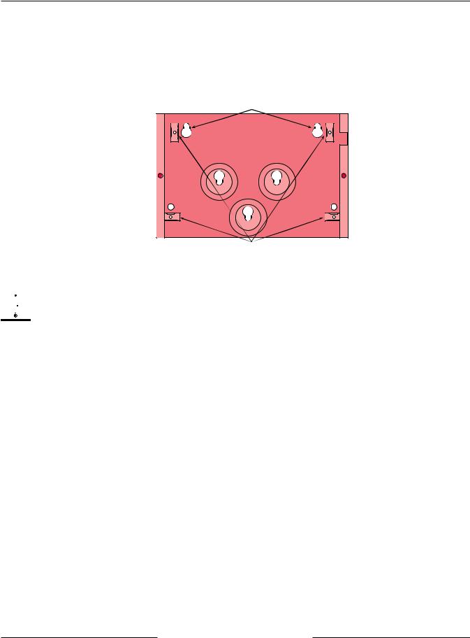
Use the mounting holes (upper left and lower right corners) to mount the D7042. The D7042 normally is mounted outside of the FACP enclosure.
Mounting Hole |
Mounting Hole |
Rear Wire Entrance |
Surface Wire Entrance |
Figure 1: Mounting the D7042
D7042/D7042B
Installation Instructions
3.2Mounting the D7042B
The D7042B will come partially preassembled with the circuit board attached to the mounting skirt.
Select a mounting location for the D7042B.
Using the enclosure as a template, mark the mounting holes on the mounting surface and make an opening for the
unit’s wiring.
Mounting Holes
Attach Mounting Skirt Here
Figure 2: Mounting the D7042B
Next, attach the mounting skirt if applicable (with the circuit board attached) to the enclosure (hardware provided). Then complete all wiring (see Section 4.0). Once installation and wiring is completed, attach the enclosure cover and secure with the screws (provided).


 Be sure all wiring is unpowered before routing. Do not use shielded or twisted pair cable.
Refer to the D7039 Installation Guide (P/N: 38685) for multiplex wiring requirements. The length of the wire connected to the loop inputs on the D7042/D7042B must be less than 250 ft. (76 m) per loop. Route wiring as necessary from the D7039 in the FACP enclosure and from remote devices to the D7042/D7042B. If the wiring is to run along the surface of the enclosure, open the D7042/D7042B surface wire entrance. See Figure 2.
|
D7042/D7042B Installation Instructions |
|
F01U262014-01 |
Page 2 |
© 2011 Bosch Security Systems, Inc. |

D7042/D7042B
Installation Instructions
4.0 Wiring
Locking tab
|
P3 |
|
DIP switch |
|
Tamper Switch |
|
P2 |
+ – + – 1 2 3 4 5 6 7 8 |
|
POWER |
BUS |
|
Rear Wire Entrance |
 Surface Wire Entrance
Figure 3: D7042/D7042B Front View without Cover
|
|
|
P2 |
|
|
|
|
|
Since NFPA 72 does not allow |
|
|
|
|
|
|
|
|
redundant/duplicate ground paths, |
|
|
|
|
|
|
|
|
do not connect wiring to the BUS (-) |
|
|
|
|
|
|
|
|
terminal on this module for fire |
|
|
|
|
|
|
|
|
applications. Only the BUS (+) needs |
|
|
|
|
|
|
|
|
to be connected. |
|
|
|
|
|
|
|
|
When used with a D7039, power is |
+ – + – 1 |
2 3 |
4 5 |
6 7 |
8 |
|||
connected to the option bus power |
POWER BUS |
|
|
|
|
|
|
|
terminals (RA or RB (+), BA or BB (-)). |
|
|
|
|
|
|
|
|
Connection to 24 VDC sources will |
|
|
|
|
|
|
|
|
damage the D7042/D7042B. |
|
|
|
|
|
|
|
|
|
NO |
NO |
NO |
NO |
NO |
NO |
NO |
NO |
To D7024 Option Bus RA (or RB) terminal |
|
|
|
|
|
|
|
|
To D7024 Option Bus BA (or BB) terminal |
NC |
NC |
NC |
NC |
NC |
NC |
NC |
NC |
|
|
|
|
|
|
|
|
|
To D7039 MUX |
|
|
|
|
|
|
|
|
bus terminal |
|
|
|
|
|
|
|
|
|
47 k ohm |
47 k ohm |
47 k ohm |
47 k ohm |
||||
|
resistors |
resistors |
resistors |
resistors |
||||
EOL P/N: 28010
Figure 4: Wiring the D7042/D7042B
|
D7042/D7042B Installation Instructions |
|
© 2011 Bosch Security Systems, Inc. |
Page 3 |
F01U262014-01 |
 Loading...