


1
ABB Micro drives
User’s manual
ACS255 drives (0.5…30 hp) (115V-480V Variants)
ABB Micro drives
List of related manuals
Option manuals and guides |
Code (English) |
|
|
ACS255 user’s manual for 600V variants |
3AXD10000528265 |
ACS255 user’s manual for 115-480V variants |
3AXD10000528266 |
You can find manuals and other product documents in PDF format on the Internet. Go to www.abb.com/drives and select Document Library. You can browse the library or enter selection criteria, for example a document code, in the search field. For manuals not available in the Document library, contact your local ABB representative
3
ACS255 drives
0.5…30 hp
User’s manual
3AXD10001010247 Rev A EN EFFECTIVE: 2019-11-10
© 2019 ABB Oy. All Rights Reserved.
4

5
1. Table of Contents
1.Table of Contents __________________________________________________________________5
ACS255 – IP20 (115V) |
EASY START-UP GUIDE _________________________________________7 |
|
ACS255 – IP66 |
(115-480V Switched Variants) EASY START-UP GUIDE ____________________________8 |
|
ACS255 – IP66 |
(115-480V Non-Switched Variants) EASY START-UP GUIDE ________________________9 |
|
2.Safety ___________________________________________________________________________11
2.1.What this chapter contains______________________________________________________________11
2.2.Use of warnings_______________________________________________________________________11
2.3.Safety in installation and maintenance ____________________________________________________11
2.4.Safety in start-up and operation _________________________________________________________12
3.General Information and Ratings_____________________________________________________14
3.1.Type designation key __________________________________________________________________14
3.2.Drive Model Numbers – IP20 ____________________________________________________________14
3.3.Drive Model Numbers – IP66 ____________________________________________________________14
4.Mechanical Installation_____________________________________________________________15
4.1.General _____________________________________________________________________________15
4.2.Mechanical Dimensions and Mounting – IP20 Open Units _____________________________________15
4.3.Guidelines for Enclosure Mounting – IP20 Units _____________________________________________15
4.4.Mechanical Dimensions – IP66 (Nema 4X) Enclosed Units _____________________________________16
4.5.Guidelines for Mounting Enclosed Units ___________________________________________________16
4.6.Gland Plate and Lock Out _______________________________________________________________17
4.7.Removing the Terminal Cover ___________________________________________________________17
5.Power Wiring_____________________________________________________________________18
5.1.Grounding the Drive ___________________________________________________________________18
5.2.Wiring Precautions ____________________________________________________________________19
5.3.Connection Diagram ___________________________________________________________________20
5.4.Drive & Motor Connections _____________________________________________________________21
5.5.Motor Terminal Box Connections_________________________________________________________21
5.6.Using the REV/Off/FWD Selector Switch (IP66 Switched Version Only) __________________________22
5.7.Using the Internal Potentiometer (IP66 Switched Version Only) ________________________________23
6.Control Wiring ____________________________________________________________________24
6.1.Control Terminal Connections ___________________________________________________________24
6.2.RJ45 Data Connection __________________________________________________________________24
7.Operation________________________________________________________________________25
7.1.Managing the Keypad __________________________________________________________________25
7.2.Changing Parameters __________________________________________________________________25
7.3.Resetting to Factory Default Settings______________________________________________________25
8.Quick Start-up and Control __________________________________________________________26
6
8.1.Motor Control Selection (Advanced Parameter Mode) _______________________________________26
8.2.Operating Mode Selection ______________________________________________________________26
8.3.Quick Start-up Terminal Control _________________________________________________________26
8.4.Quick Start-up Keypad Control___________________________________________________________27
8.5.Drive Operating Displays. _______________________________________________________________27
9.Application Macros ________________________________________________________________28
9.1.Overview of macros ___________________________________________________________________28
10.Parameters ______________________________________________________________________31
10.1.Parameter Structure ___________________________________________________________________31
10.2.Parameters in the Short parameter mode__________________________________________________32
10.3.Read Only Status parameters____________________________________________________________34
10.4.Parameters in the Long parameter mode __________________________________________________36
10.5.Adjusting the Voltage / Frequency (V/f) characteristics _______________________________________41
10.6.Motor Thermistor Connection ___________________________________________________________41
10.7.Parameters in the Advanced parameter mode ______________________________________________42
10.8.Preventing un-authorized parameter editing._______________________________________________43
11.Modbus RTU Communications _______________________________________________________44
11.1.Introduction _________________________________________________________________________44
11.2.Modbus RTU Specification ______________________________________________________________44
11.3.RJ45 Connector Configuration ___________________________________________________________44
11.4.Modbus Telegram Structure_____________________________________________________________44
11.5.Modbus Register Map__________________________________________________________________44
11.6.Modbus Parameter Register Map ________________________________________________________45
12.Technical Data____________________________________________________________________46
12.1.Environmental________________________________________________________________________46
12.2.Rating Tables_________________________________________________________________________46
12.3.Overload ____________________________________________________________________________47
12.4.Additional Information for UL Compliance _________________________________________________47
12.5.Derating Information __________________________________________________________________47
12.6.Mains Line input Reactors ______________________________________________________________48
13.Appendix: Permanent magnet synchronous motors (PMSMs) ______________________________49
13.1.PMSM Motor nameplate data entry.______________________________________________________49
13.2.PMSM Motor Auto-tune. _______________________________________________________________49
13.3.Troubleshooting ______________________________________________________________________49
14.Trouble Shooting __________________________________________________________________50
14.1.Fault Code Messages___________________________________________________________________50
7
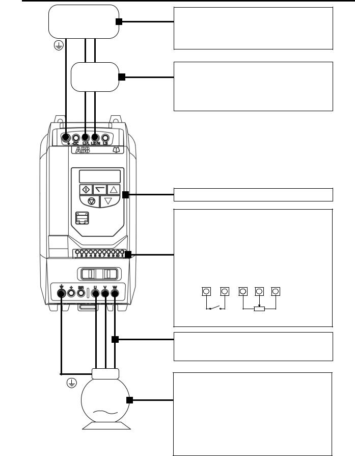
ACS255 – IP20 (115V) |
EASY START-UP GUIDE |
AC SupplyVoltage
(50/60Hz)
L1 L2
Earth L N
Fuses
M
Supply Voltage :
-115 Volts
-1 Phase
-Check the drive rating information on page 46
Fuses, Cable Sizes :
-Fuse Rating recommendation values given on page 46
-Cable size recommendation values given on page 46
-Always follow local and national codes of practice
Keypad operation can be found in sections 7 and 8
Control Terminals :
Based on the default, out of box settings –
-Connect a Start/Stop switch between terminals 1& 2
-Close the switch to start
-Open the switch to stop
-To vary the speed from minimum (0Hz) to maximum
(60Hz) Connect a 10kΩ potentiometer to terminals 5,6
& 7.
1 |
2 |
5 |
6 |
7 |
|
|
|
|
|
Stop - Run |
10kΩ |
|||
Speed Pot |
||||
|
||||
Motor Cable Sizes
-Cable size recommendation values given on page 46
Motor Connections
-Check for Star or Delta connection according to the motor voltage rating (See page 21)
Motor Nameplate Details
-Enter the motor rated voltage in parameter 9905
-Enter the motor rated current in parameter 9906
-Enter the motor rated frequency in parameter 9907

8
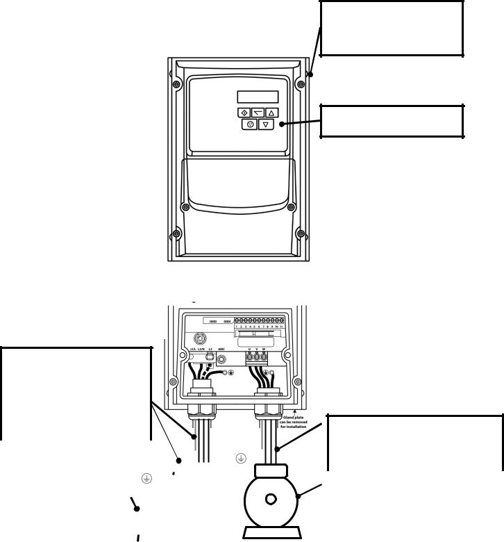
ACS255 – IP66 (115-480V Switched Variants) |
EASY START-UP GUIDE |
|
|
Local Speed Potentiometer
The local speed potentiometer will adjust the output frequency from minimum (Parameter 2007, default setting = 0Hz) to maximum (Parameter 2008, default setting = 60Hz)
Mechanical Mounting
-Information can be found on page 16
Run Reverse / Off / Run Forward
Switch Keypad operation can be found in
section 7 and 8
With the factory parameter settings, this switch allows the drive to be started in the forward and reverse operating directions. Alternative switch functions can be programmed, such as Local/Remote, hand / Off/ Auto, see page 22.
Local Power disconnect with lock out provision
Fuses, Cable Sizes :
-Fuse Rating recommendation values given on page 46
-Cable size recommendation values given on page 46
-Always follow local and national
|
codes of practice. |
|
|
|
|
|
|
|
|
|
|
|
|
|
|
Motor Cable Sizes |
||
|
|
|
|
|
|
|
|
|
|
|
|
|
|
|
|
|
||
|
|
|
|
|
|
|
|
|
|
|
|
|
|
- |
Cable size recommendation values given |
|||
|
|
|
|
|
|
|
|
|
|
|
|
|
|
|||||
|
|
|
|
|
|
|
|
|
|
|
|
|
|
|
|
|
|
on page 46 |
Supply Voltage : |
|
|
|
|
|
|
Fuses |
|
|
|
|
|
|
|
|
|||
|
|
|
|
|
|
|
|
|
|
|
|
|
|
|||||
|
|
|
|
|
|
|
|
|
|
|
|
|
|
|
|
|||
- |
115, 230, 400, 480 Volts |
|
|
|
|
|
|
|
|
|
|
|
|
|
|
|
Motor Connections |
|
|
|
|
|
|
|
|
|
|
|
|
|
|
|
|
||||
|
|
|
|
|
|
|
|
|
|
|
|
|
|
|
|
|
||
- |
1 or 3 Phase |
|
|
|
|
|
|
|
|
|
|
|
|
|
|
|
- |
Check for Star or Delta connection |
- |
Check the drive rating |
|
|
|
|
|
|
|
|
|
|
|
||||||
|
Earth |
L |
N |
|
|
|
|
Motor |
|
according to the motor voltage rating (See |
||||||||
|
information on page 46 |
|
|
|
|
|
|
|||||||||||
|
|
|
|
|
|
|
|
|
page 21) |
|||||||||
|
|
|
|
|
|
L1 |
|
L2 |
L3 |
|
|
|
|
|
||||
|
|
|
|
|
|
|
|
|
|
|
|
|
||||||
|
|
|
AC Supply Voltage |
|
|
|
|
|
|
Motor Nameplate Details |
||||||||
|
|
|
|
|
|
|
|
|
||||||||||
|
|
|
|
|
(50 / 60Hz) |
|
|
|
|
|
|
|||||||
|
|
|
|
|
|
|
|
|
|
|
|
|
||||||
|
|
|
|
|
|
|
|
|
|
|
|
- |
Enter the motor rated voltage in |
|||||
|
|
|
|
|
|
|
|
|
|
|
|
|
|
|
|
|
|
parameter 9905 |
|
|
|
|
|
|
|
|
|
|
|
|
- |
Enter the motor rated current in |
|||||
|
|
|
|
|
|
|
|
|
|
|
|
|
|
|
|
|
|
parameter 9906 |
|
|
|
|
|
|
|
|
|
|
|
|
- |
Enter the motor rated frequency in |
|||||
|
|
|
|
|
|
|
|
|
|
|
|
|
|
|
|
|
|
parameter 9907 |
|
|
|
|
|
|
|
|
|
|
|
|
|
|
|
|
|
|
|
9
ACS255 – IP66 (115-480V Non-Switched Variants) |
EASY START-UP GUIDE |
|
|
Mechanical Mounting
- Information can be found on page 16
Keypad operation can be found in section 7 and 8
Fuses, Cable Sizes :
-Check the drive rating information on page 46
Fuses, Cable Sizes :
-Fuse Rating recommendation values given on page 46
-Cable size recommendation values given on page 46
-Always follow local and national
|
codes of practice. |
|
|
|
|
|
|
|
|
|
|
|
|
|
|
Motor Cable Sizes |
||
|
|
|
|
|
|
|
|
|
|
|
|
|
|
|
|
|
||
|
|
|
|
|
|
|
|
|
|
|
|
|
|
- |
Cable size recommendation values given |
|||
|
|
|
|
|
|
|
|
|
|
|
|
|
|
|||||
|
|
|
|
|
|
|
|
|
|
|
|
|
|
|
|
|
|
on page 46 |
Supply Voltage : |
|
|
|
|
|
|
Fuses |
|
|
|
|
|
|
|
|
|||
|
|
|
|
|
|
|
|
|
|
|
|
|
|
|||||
|
|
|
|
|
|
|
|
|
|
|
|
|
|
|
|
|||
- |
115, 230, 400, 480 Volts |
|
|
|
|
|
|
|
|
|
|
|
|
|
|
|
Motor Connections |
|
|
|
|
|
|
|
|
|
|
|
|
|
|
|
|
||||
|
|
|
|
|
|
|
|
|
|
|
|
|
|
|
|
|
||
- |
1 or 3 Phase |
|
|
|
|
|
|
|
|
|
|
|
|
|
|
|
- |
Check for Star or Delta connection |
- |
Check the drive rating |
|
|
|
|
|
|
|
|
|
|
|
|
|||||
|
Earth |
L |
N |
|
|
|
|
Motor |
|
according to the motor voltage rating (See |
||||||||
|
information on page 46 |
|
|
|
|
|
|
|||||||||||
|
|
|
|
|
|
|
|
|
page 21) |
|||||||||
|
|
|
|
|
|
L1 |
|
L2 |
L3 |
|
|
|
|
|
||||
|
|
|
|
|
|
|
|
|
|
|
|
|
||||||
|
|
|
AC Supply Voltage |
|
|
|
|
|
|
Motor Nameplate Details |
||||||||
|
|
|
|
|
|
|
|
|
||||||||||
|
|
|
|
|
(50 / 60Hz) |
|
|
|
|
|
|
|||||||
|
|
|
|
|
|
|
|
|
|
|
|
|
||||||
|
|
|
|
|
|
|
|
|
|
|
|
|
|
|
|
|
- |
Enter the motor rated voltage in |
|
|
|
|
|
|
|
|
|
|
|
|
|||||||
|
|
|
|
|
|
|
|
|
|
|
|
|
|
|
|
|
|
parameter 9905 |
|
|
|
|
|
|
|
|
|
|
|
|
- |
Enter the motor rated current in |
|||||
|
|
|
|
|
|
|
|
|
|
|
|
|
|
|
|
|
|
parameter 9906 |
|
|
|
|
|
|
|
|
|
|
|
|
- |
Enter the motor rated frequency in |
|||||
|
|
|
|
|
|
|
|
|
|
|
|
|
|
|
|
|
|
parameter 9907 |
|
|
|
|
|
|
|
|
|
|
|
|
|
|
|
|
|
|
|
Declaration of Conformity
The manufacturer hereby states that the ACS255 product range conforms to the relevant safety provisions of the following council directives:
2014/30/EU (EMC) and 2014/35/EU (LVD) 2011/65/EU (RoHS)
EN 61800-5-1: 2007 |
Adjustable speed electrical power drive systems. Safety requirements. Electrical, thermal and energy. |
|
|
EN 61800-3 2nd Ed: 2004 |
Adjustable speed electrical power drive systems. EMC requirements and specific test methods |
/ A1:2012 |
|
EN 55011: 2007 |
Limits and Methods of measurement of radio disturbance characteristics of industrial, scientific and |
|
medical (ISM) radio-frequency equipment (EMC) |
EN60529 : 1992 |
Specifications for degrees of protection provided by enclosures |
Electromagnetic Compatibility
All drives are designed with high standards of EMC in mind.
It is the responsibility of the installer to ensure that the equipment or system into which the product is incorporated complies with the EMC legislation of the country of use. Within the European Union, equipment into which this product is incorporated must comply with the EMC Directive 2004/108/EC. When using an ACS255 with an external filter, compliance with the following EMC Categories, as defined by EN61800- 3:2004 can be achieved:
|
Drive Type / Rating |
|
EMC Category |
|
||
|
|
|
|
First Environment Category C1 |
First Environment Category C2 |
Second Environment Category C3 |
|
ACS255-_ _U… |
Use External EMC Filter |
Use External EMC Filter |
Use External EMC Filter |
||
|
|
|
|
|
||
|
Note |
|
Compliance with EMC standards is dependent on a number of factors including the environment in which the drive is installed, |
|||
|
|
motor switching frequency, motor, cable lengths and installation methods adopted. |
|
|||
|
|
|
|
|||
|
|
|
For shielded motor cable lengths greater than 100m and up to 200m, an output dv/dt filter must be used (please refer to |
|||
|
|
|
http://www.abb.com/ProductGuide for further details) |
|
||
All rights reserved. No part of this User Guide may be reproduced or transmitted in any form or by any means, electrical or mechanical including photocopying, recording or by any information storage or retrieval system without permission in writing from the publisher.
ABB Drives Ltd © 2016
The manufacturer accepts no liability for any damage caused during or resulting from transport, receipt of delivery, installation or commissioning. The manufacturer also accepts no liability for damage or consequences resulting from inappropriate, negligent or incorrect installation, incorrect adjustment of the operating parameters of the drive, incorrect matching of the drive to the motor, incorrect installation, unacceptable dust, moisture, corrosive substances, excessive vibration or ambient temperatures outside of the design specification.
The contents of this User Guide are believed to be correct at the time of printing. In the interest of a commitment to a policy of continuous improvement, the manufacturer reserves the right to change the specification of the product or its performance or the contents of the User Guide without notice.
This User Guide is for use with version 2.02 Software.
User Guide Revision A
This user guide is the “original instructions” document. All non-English versions are translations of the “original instructions”.
The manufacturer adopts a policy of continuous improvement and whilst every effort has been made to provide accurate and up to date information, the information contained in this User Guide should be used for guidance purposes only and does not form the part of any contract.
11
2. Safety
2.1. What this chapter contains
This chapter contains the safety instructions which you must follow when installing, operating and servicing the drive. If ignored, physical injury or death may follow, or damage may occur to the drive, motor or driven equipment. Read the safety instructions before you work on the unit.
2.2. Use of warnings
Warnings caution you about conditions which can result in serious injury or death and/or damage to the equipment and advice on how to avoid the danger. The following warning symbols are used in this manual:
Electricity warning warns of hazards from electricity which can cause physical injury and/or damage to the equipment.
General warning warns about conditions, other than those caused by electricity, which can result in physical injury and/or damage to the equipment.
2.3. Safety in installation and maintenance
These warnings are intended for all who work on the drive, motor cable or motor.
Electricity safety
WARNING! Ignoring the instructions can cause physical injury or death, or damage to the equipment.
Only qualified electricians are allowed to install and maintain the drive!
•Never work on the drive, motor cable or motor when input power is applied. After disconnecting the input power, always wait for 10 minutes to let the intermediate circuit capacitors discharge before you start working on the drive, motor or motor cable.
Always ensure by measuring with a multimeter (impedance at least 1 Mohm) that:
1.There is no voltage between the drive input phases L1, L2 and L3 and the ground.
2.There is no voltage between terminals + and BR and the ground.
•Do not work on the control cables when power is applied to the drive or to the external control circuits. Externally supplied control circuits may carry dangerous voltage even when the input power of the drive is switched off.
•Do not make any insulation or voltage withstand tests on the drive.
•Be sure the system is properly grounded before applying power. Do not apply AC power before you ensure that all grounding instructions have been followed. Electrical shock can cause serious or fatal injury.
Note:
Even when the motor is stopped, dangerous voltage is present at the power circuit terminals L1, L2, L3 and U, V, W and + and BR.

12
General safety
WARNING! Ignoring the following instructions can cause physical injury or death, or damage to the equipment.
•The drive is not field repairable. Never attempt to repair a malfunctioning drive; contact your local ABB representative or Authorized Service Centre for replacement.
•Make sure that dust from drilling does not enter the drive during the installation. Electrically conductive dust inside the drive may cause damage or lead to malfunction.
•Ensure sufficient cooling.
2.4.Safety in start-up and operation
These warnings are intended for all who plan the operation, start up or operate the drive.
WARNING! Ignoring the following instructions can cause physical injury or death, or damage to the equipment.
•Before adjusting the drive and putting it into service, make sure that the motor and all driven equipment are suitable for operation throughout the speed range provided by the drive. The drive can be adjusted to operate the motor at speeds above and below the speed provided by connecting the motor directly to the power line.
•Do not activate automatic fault reset functions if dangerous situations can occur. When activated, these functions reset the drive and resume operation after a fault.
•Do not control the motor with an AC contactor or disconnecting device (disconnecting means); use instead the control panel start and stop keys and or external commands (I/O). The maximum allowed number of charging cycles of the DC capacitors (that is, power-ups by applying power) is two per minute.
Note:
•When parameter 1103 PRIMARY COMMAND SOURCE MODE is not set to 1 or 2, the stop key on the control panel will not stop the drive. To stop the drive open terminal 2 of the drive control terminals.

13
Danger: Indicates a risk of electric shock, which, if not avoided, could result in damage to the equipment and possible injury or death.
Danger: Indicates a potentially hazardous situation other than electrical, which if not avoided, could result in damage to property.
The ACS255 variable speed drive is intended for professional installation and commissioning into complete equipment or systems as part of a fixed installation. If installed incorrectly it may present a safety hazard. The ACS255 uses high voltages and currents, carries a high level of stored electrical energy, and is used to control mechanical plant that may cause injury. Close attention is required to system design and electrical installation to avoid hazards in either normal operation or in the event of equipment malfunction. Only qualified electricians are allowed to install and maintain this product.
System design, installation, commissioning and maintenance must be carried out only by personnel who have the necessary training and experience. They must carefully read this safety information and the instructions in this Guide and follow all information regarding transport, storage, installation and use of the ACS255, including the specified environmental limitations.
Do not perform any flash test or voltage withstand test on the ACS255. Any electrical measurements required should be carried out with the ACS255 disconnected.
Electric shock hazard! Disconnect and ISOLATE the ACS255 before attempting any work on it. High voltages are present at the terminals and within the drive for up to 10 minutes after disconnection of the electrical supply. Always ensure by using a suitable multimeter that no voltage is present on any drive power terminals prior to commencing any work.
Where supply to the drive is through a plug and socket connector, do not disconnect until 10 minutes have elapsed after turning off the supply.
Ensure correct grounding connections. The ground cable must be sufficient to carry the maximum supply fault current which normally will be limited by the fuses. Suitably rated fuses should be fitted in the mains supply to the drive, according to any local legislation or codes.
Do not carry out any work on the drive control cables when power is applied to the drive or to the external control circuits.
Within the European Union, all machinery in which this product is used must comply with the Machinery Directive 2006/42/EC, Safety of Machinery. In particular, the machine manufacturer is responsible for providing a main switch and ensuring the electrical equipment complies with EN60204-1.
The level of integrity offered by the ACS255 control input functions – for example stop/start, forward/reverse and maximum speed is not sufficient for use in safety-critical applications without independent channels of protection. All applications where malfunction could cause injury or loss of life must be subject to a risk assessment and further protection provided where needed.
The driven motor can start at power up if the enable input signal is present.
The STOP function does not remove potentially lethal high voltages. ISOLATE the drive and wait 10 minutes before starting any work on it. Never carry out any work on the Drive, Motor or Motor cable when the input power is still applied.
The ACS255 can be programmed to operate the driven motor at speeds above or below the speed achieved when connecting the motor directly to the mains supply. Obtain confirmation from the manufacturers of the motor and the driven machine about suitability for operation over the intended speed range prior to machine start up.
Do not activate the automatic fault reset function on any systems whereby this may cause a potentially dangerous situation.
The ACS255 has an Ingress Protection rating of IP20 or IP66 depending on the model. IP20 units must be installed in a suitable enclosure.
ACS255s are intended for indoor use only.
When mounting the drive, ensure that sufficient cooling is provided. Do not carry out drilling operations with the drive in place, dust and metal shavings from drilling may lead to damage.
The entry of conductive or flammable foreign bodies should be prevented. Flammable material should not be placed close to the drive
Relative humidity must be less than 95% (non-condensing).
Ensure that the supply voltage, frequency and number of phases correspond to the rating of the ACS255 as delivered.
Never connect the mains power supply to the Output terminals U, V, W.
Do not install any type of automatic switchgear between the drive and the motor
Wherever control cabling is close to power cabling, maintain a minimum separation of 4 in. (100 mm) and arrange crossings at 90 degrees
Ensure that all terminals are tightened to the appropriate torque setting
Do not attempt to carry out any repair of the drive. In the case of suspected fault or malfunction, contact your local ABB representative for further assistance.

14
3. General Information and Ratings
This chapter contains information about the ACS255 including how to identify the drive.
3.1. Type designation key
The type designation contains information on the specification and configuration of the drive. You find the type designation label attached to the drive. The first digits from the left express the basic configuration, for example ACS255-03U-05A8-4.
The explanations of the type designation label selections are described below.
ACS255-03 U-05A8-4+B063+F278+N828
ACS255 product series
1-phase/3 phase
01 = 1-phase input
03 = 3-phase input
EMC Filter
E = Filtered
U = Non-Filtered
Output Current Rating
In format xxAy, where xx indicates the integer part and y the fractional part, For example, 05A8 means 5.8 A.
Input Voltage Range
1 = 110…115 V AC
2 = 200…240 V AC
4 = 380…480VAC
IP66 Enclosure
B063 = IP66 Indoor
B068 = IP66 Outdoor
Input Switch Assembly
(Speed potentiometer, run/stop and mains disconnect switch)
Low ambient Temperature version (-20deg C)
3.2. Drive Model Numbers – IP20
Mechanical Dimensions and Mounting information are shown in section 4.
Further Electrical Specifications are shown in section 12.2.
|
Power |
|
Output |
|
Internal DB |
|
Model Number |
|
Current |
Input switch assembly |
Frame Size |
||
(HP) |
|
transistor |
||||
|
|
(A) |
|
|
||
|
|
|
|
|
|
|
1-phase 110V…115V AC (+/-10%) - 3 Phase 230V Output |
|
|
|
|
||
ACS255-01U-02A3-1 |
0.5 |
|
2.3 |
No |
No |
E1 |
ACS255-01U-04A3-1 |
1 |
|
4.3 |
No |
No |
E1 |
ACS255-01U-05A8-1 |
1.5 |
|
5.8 |
No |
Yes |
E2 |
3.3. Drive Model Numbers – IP66
Mechanical Dimensions and Mounting information are shown in section 4.
Further Electrical Specifications are shown in section 12.2.
|
Power |
Output |
|
Internal DB |
|
|
Model Number |
Current |
Input switch assembly |
Frame Size |
|||
(HP) |
transistor |
|||||
|
(A) |
|
|
|||
|
|
|
|
|
||
3-phase 200…240V AC (+/-10%) - 3 Phase Output |
|
|
|
|
||
ACS255-03U-24A0-2+B068 |
7.5 |
24 |
No |
Yes |
E3 |
|
ACS255-03U-24A0-2+B068+F278 |
7.5 |
24 |
Yes |
Yes |
E3 |
|
ACS255-03U-30A0-2+B068 |
10 |
30 |
No |
Yes |
E4 |
|
ACS255-03U-30A0-2+B068+F278 |
10 |
30 |
Yes |
Yes |
E4 |
|
ACS255-03U-46A0-2+B068 |
15 |
46 |
No |
Yes |
E4 |
|
ACS255-03U-46A0-2+B068+F278 |
15 |
46 |
Yes |
Yes |
E4 |
|
3-phase 380…480V AC (+/-10%) - 3 Phase Output |
|
|
|
|
||
ACS255-03U-24A0-4+B068 |
15 |
24 |
No |
Yes |
E3 |
|
ACS255-03U-24A0-4+B068+F278 |
15 |
24 |
Yes |
Yes |
E3 |
|
ACS255-03U-30A0-4+B068 |
20 |
30 |
No |
Yes |
E4 |
|
ACS255-03U-30A0-4+B068+F278 |
20 |
30 |
Yes |
Yes |
E4 |
|
ACS255-03U-39A0-4+B068 |
25 |
39 |
No |
Yes |
E4 |
|
ACS255-03U-39A0-4+B068+F278 |
25 |
39 |
Yes |
Yes |
E4 |
|
ACS255-03U-46A0-4+B068 |
30 |
46 |
No |
Yes |
E4 |
|
ACS255-03U-46A0-4+B068+F278 |
30 |
46 |
Yes |
Yes |
E4 |
|

15
4. Mechanical Installation
4.1.General
•Carefully Unpack the ACS255 and check for any signs of damage. Notify the shipper immediately if any exist.
•Check the drive rating label to ensure it is of the correct type and power requirements for the application.
•Store the ACS255 in its box until required. Storage should be clean and dry and within the temperature range –40°C to +60°C
•The ACS255 should be mounted in a vertical position only on a flat, flame resistant vibration free mounting using the integral holes.
•The ACS255 must be installed in a pollution degree 1 or 2 environment only.
•Do not mount flammable material close to the ACS255
•Ensure that the minimum cooling air gaps, as detailed in sections 4.3 and 4.5 are left clear
•Ensure that the ambient temperature range does not exceed the permissible limits for the ACS255 given on page 46.
•Provide suitable clean, moisture and contaminant free cooling air sufficient to fulfil the cooling requirements of the ACS255 according to sections 4.3 and 12.1.
4.2.Mechanical Dimensions and Mounting – IP20 Open Units
I
J
|
|
|
|
A |
||
|
|
|
|
|||
|
|
|
|
|||
D |
||||||
|
B |
|
||||
|
|
|||||
|
|
|
|
|||
|
|
|
|
|
|
|
|
|
C |
|
|||
|
|
|
|
|
|
|
H |
|
|
|
G |
E |
H |
F |
|
Drive |
|
A |
|
B |
C |
|
|
D |
E |
|
|
F |
|
G |
H |
|
|
I |
|
J |
|
Weight |
||||||||
Frame |
mm |
|
in |
mm |
|
in |
mm |
|
in |
mm |
|
in |
mm |
|
in |
mm |
in |
mm |
|
in |
mm |
|
in |
mm |
in |
mm |
|
in |
Kg |
Ib |
Size |
|
|
|
|
|
|
|
|
||||||||||||||||||||||
|
|
|
|
|
|
|
|
|
|
|
|
|
|
|
|
|
|
|
|
|
|
|
|
|
|
|
|
|
|
|
1 |
173 |
|
6.81 |
160 |
|
6.30 |
109 |
|
4.29 |
162 |
|
6.38 |
5 |
|
0.20 |
123 |
4.84 |
82 |
|
3.23 |
50 |
|
1.97 |
5.5 |
0.22 |
10 |
|
0.39 |
1.0 |
2.20 |
2 |
221 |
|
8.70 |
207 |
|
8.15 |
137 |
|
5.39 |
209 |
|
8.23 |
5.3 |
|
0.21 |
150 |
5.91 |
109 |
|
4.29 |
63 |
|
2.48 |
5.5 |
0.22 |
10 |
|
0.39 |
1.7 |
3.75 |
NOTE
Maximum Control Terminal Torque Settings of 0.5 Nm (4.5 lb-in)
Maximum Power Terminal Torque Settings of 1 Nm (9 lb-in)
4.3.Guidelines for Enclosure Mounting – IP20 Units
•Installation should be in a suitable enclosure, according to EN60529 or other relevant local codes or standards.
•Enclosures should be made from a thermally conductive material.
•Where vented enclosures are used, there should be free space clearance above and below the drive to ensure good air circulation – see the diagram below for minimum free space clearance. Air should be drawn in below the drive and expelled above the drive.
•In any environments where the conditions require it, the enclosure must be designed to protect the ACS255 against ingress of airborne dust, corrosive gases or liquids, conductive contaminants (such as condensation, carbon dust, and metallic particles) and sprays or splashing water from all directions.
•High moisture, salt or chemical content environments should use a suitably sealed (non-vented) enclosure.
The enclosure design and layout should ensure that the adequate ventilation paths and clearances are left to allow air to circulate through the drive heatsink. ABB Drives recommend the following minimum mounting clearance requirements for drives mounted in non-ventilated metallic enclosures:-
X
 Y
Y 
X
|
|
|
|
|
|
|
|
Drive |
|
X |
|
Y |
|
|
Z |
|||
|
|
|
|
|
|
|
|
|||||||||||
Z |
|
|
|
|
|
|
|
Size |
Above & |
Either |
|
|
Between |
|||||
|
|
|
|
|
|
|
|
|
Below |
|
Side |
|
|
|
|
|||
|
|
|
|
|
|
|
|
|
mm |
|
in |
mm |
|
in |
|
mm |
|
in |
|
|
|
|
|
|
|
|
|
|
|
|
|
|
|
|
|
|
|
|
|
|
|
|
|
|
1 |
50 |
|
1.97 |
50 |
|
1.97 |
|
33 |
|
1.30 |
|
|
|
|
|
|
|
|
2 |
75 |
|
2.95 |
50 |
|
1.97 |
|
46 |
|
1.81 |
|
|
|
|
|
Y |
|
|
|
Note : |
|
|
|
|
|
|
|
|
|
|
|
|
|
|
|
|
|
Dimension Z assumes that the drives are mounted side-by-side with |
|||||||||||
|
|
|
|
|
|
|
|
|||||||||||
|
|
|
|
|
|
|
|
no clearance. |
|
|
|
|
|
|
|
|
|
|
|
|
|
|
|
|
|
|
Typical drive heat losses are 3% of operating load conditions. |
||||||||||
|
|
|
|
|
|
|
|
Above are guidelines only and the operating ambient temperature of |
||||||||||
|
|
|
|
|
|
|
|
the drive MUST be maintained at all times. |
|
|
|
|||||||
|
|
|
|
|
|
|
|
|
|
|
|
|
|
|
|
|
|
|

16
4.4. Mechanical Dimensions – IP66 (Nema 4X) Enclosed Units
Drive |
|
A |
B |
|
|
C |
|
D |
|
E |
|
Weight |
|||
Frame |
|
|
in |
mm |
|
in |
mm |
|
in |
mm |
in |
mm |
in |
kg |
Ib |
Size |
mm |
|
|
|
|||||||||||
|
|
|
|
|
|
|
|
|
|
|
|
|
|
||
|
|
|
|
|
|
|
|
|
|
|
|
|
|
|
|
3 |
310.0 |
|
12.2 |
210.5 |
|
8.29 |
238 |
|
9.37 |
251.5 |
9.90 |
197.5 |
7.78 |
7.0 |
15.4 |
4 |
360.0 |
|
14.17 |
240 |
|
9.45 |
275 |
|
10.83 |
300.0 |
11.08 |
226.0 |
8.89 |
9.5 |
20.9 |
The size 3 and 4 product has 4 symmetrical mounting points
NOTE Maximum Control Terminal Torque Settings of 0.5 Nm (4.5 lb-in)
Maximum Power Terminal Torque Settings of 1 Nm (9 lb-in) / Size 4 = 4.1 Nm (36.5 Ib-in)
4.5.Guidelines for Mounting Enclosed Units
•Before mounting the drive, ensure that the chosen location meets the environmental condition requirements for the drive shown in section 12.1
•The drive must be mounted vertically, on a suitable flat surface
•The minimum mounting clearances as shown in the table below must be observed
•The mounting site and chosen mountings should be sufficient to support the weight of the drives
•The Enclosed ACS255s can be installed side-by-side with their heatsink flanges touching. This gives adequate ventilation space between drives.
•If the ACS255 is to be installed above another drive or any other heat-producing device, the minimum vertical spacing (X) is 150mm (5.9 inches) above and below.
=/> 150mm (5.9 inches)
=/> 150mm (5.9 inches)
 Loading...