


Canopy TM Backhaul Module
USER MANUA L
BH02-UM-en
Issue 3
October 2003
© 2003 Motorola, Inc. All rights reserved. Printed in the U.S.A

NOTICES
Important Note on Modifications
Intentional or unintentional changes or modifications to the equipment must not be made unless under the express consent of the party responsible for compliance. Any such modifications could void the user’s authority to operate the equipment and will void the manufacturer’s warranty.
U.S. Federal Communication Commision (FCC) and Industry Canada (IC) Notification
This device complies with part 15 of the U. S. FCC Rules and Regulations and with RSS-210 of Industry Canada. Operation is subject to the following two conditions: (1) This device may not cause harmful interference, and (2) This device must accept any interference received, including interference that may cause undesired operation. In Canada, users should be cautioned to take note that high power radars are allocated as primary users (meaning they have priority) of 5250 – 5350 MHz and 5650 – 5850 MHz and these radars could cause interference and/or damage to license-exempt local area networks (LELAN).
This equipment has been tested and found to comply with the limits for a Class B digital device, pursuant to Part 15 of the U.S. FCC Rules and with RSS-210 of Industry Canada. These limits are designed to provide reasonable protection against harmful interference in a residential installation. This equipment generates, uses, and can radiate radio-frequency energy and, if not installed and used in accordance with these instructions, may cause harmful interference to radio communications. If this equipment does cause harmful interference to radio or television reception, which can be determined by turning the equipment on and off, the user is encouraged to correct the interference by one or more of the following measures:
Increase the separation between the affected equipment and the unit;
Connect the affected equipment to a power outlet on a different circuit from that which the receiver is connected to;
Consult the dealer and/or experienced radio/TV technician for help.
FCC IDs and Industry Canada Certification Numbers are listed in the following table:
Module |
Operating Frequency |
Maximum |
Reflector |
FCC ID |
Industry Canada |
Types |
Range |
Transmitter |
|
|
Cert Number |
|
|
Power |
|
|
|
SM AP BH |
U-NII 5250-5350 MHz |
200mW |
Not Allowed |
ABZ89FC3789 |
109W-5200 |
SM AP BH |
U-NII 5725-5825 MHz |
200mW |
Allowed on SM and |
ABZ89FC4816 |
109W-5700 |
|
|
|
BH |
|
|
SM AP BH |
ISM 5725-5850 MHz |
200mW |
Allowed on SM and |
ABZ89FC5804 |
109W-5700 |
|
|
|
BH |
|
|
The term “IC:” before the radio certification number only signifies that Industry Canada technical specifications were met.
European Community Notification
Notification of Intended Purpose of Product Uses
This product is a two-way radio transceiver suitable for use in Broadband RLAN systems. It uses operating frequencies which are not harmonized through the EC. All licenses must be obtained before using the product in any EC country.
Declaration of conformity:
Motorola declares the GHz radio types listed below comply with the essential requirements and other relevant provisions of Directive1999/5/EC.
Relevant Specification
EN 301 893 or similar - radio spectrum
EN301489-17 - EMC
EN60950 - safety
Product Details for Products Tested for Compliance with Relevant EC Directives
Module |
Band |
Maximum |
Effective Isotropic |
Modulation Type |
Operating Channels |
Non- |
Type |
Frequency |
Transmitter |
Radiated Power |
|
|
overlapping |
|
Range |
Power |
(EIRP) |
|
|
Channel |
|
|
|
|
|
|
Spacing |
Access Point |
5.725 to 5.825 |
200mW RMS |
1 Watt EIRP |
High Index 2-level |
5745 to 5805 MHz in |
20 MHz |
|
GHz |
|
|
FSK |
5 MHz increments |
|
|
|
|
|
|
|
|
Subscriber |
5.725 to 5.825 |
200mW RMS |
1 Watt EIRP |
High Index 2-level |
5745 to 5805 MHz in |
20 MHz |
Module |
GHz |
|
|
FSK |
5 MHz increments |
|
Subscriber |
5.725 to 5.825 |
200mW RMS |
63 Watts EIRP |
High Index 2-level |
5745 to 5805 MHz in |
20 MHz |
Module with |
GHz |
|
|
FSK |
5 MHz increments |
|
Reflector |
|
|
|
|
|
|
Backhaul |
5.725 to 5.825 |
200mW RMS |
1 Watt EIRP |
High Index 2-level |
5745 to 5805 MHz in |
20 MHz |
|
GHz |
|
|
or 4-level FSK |
5 MHz increments |
|
Backhaul User Manual Issue 3 |
Page 2 of 53 |

Backhaul with |
5.725 to 5.825 |
200mW RMS |
63 Watts EIRP |
High Index 2-level |
5745 to 5805 MHz in |
20 MHz |
Reflector |
GHz |
|
|
or 4-level FSK |
5 MHz increments |
|
Canopy can be configured to operate at a range of frequencies, but at this time, only channels from 5745 MHz through 5805 MHz of the 5.7 GHz product have been tested for compliance with relevant EC directives. Before configuring equipment to operate outside this range, please check with your regulator.
Exposure Note
The Canopy Subscriber Module (SM) must be installed to provide a separation distance of at least 20 cm (7.9 in) from all persons, when adding the Canopy reflector dish (in the 5.7 GHz band), the reflector dish must be installed to provide a separation distance of at least 1.5m (59.1 in) from all persons and does not emit a RF field in excess of Health Canada limits for the general population; consult Safety Code 6, obtainable from Health Canada’s website http://www.hc-sc.gc.ca/rpb.
In both configurations the maximum RMS power does not exceed 200mW.
The applicable power density exposure limit is 10 Watt/m2, according to the FCC OET Bulletin 65, the ICNIRP guidelines, and the Health Canada Safety Code 6. The corresponding compliance distances referenced above have been determined by assuming worst-case scenarios. The peak power density (S) in the far-field of a radio-frequency source with rms transmit power P and antenna gain G at a distance d is
S = P G
4π d2
In the case of the Canopy SM without reflector, the gain is 8 dBi (a factor of 6.3), so the peak power density equals the exposure limit at a distance of 10 cm. A four-fold additional compliance margin is artificially introduced by doubling the distance to 20 cm.
In the case of the Canopy SM with reflector, the gain is 26 dBi (a factor of 400), so the peak power density equals the exposure limit at a distance of about 80 cm. An almost four-fold additional compliance margin is artificially introduced by defining the compliance distance of 1.5 m. The compliance distance is greatly overestimated in this case because the far-field equation neglects the physical dimension of the antenna, which is modeled as a point-source.
Software License Terms and Conditions
ONLY OPEN THE PACKAGE, OR USE THE SOFTWARE AND RELATED PRODUCT IF YOU ACCEPT THE TERMS OF THIS LICENSE. BY BREAKING THE SEAL ON THIS DISK KIT / CDROM, OR IF YOU USE THE SOFTWARE OR RELATED PRODUCT, YOU ACCEPT THE TERMS OF THIS LICENSE AGREEMENT. IF YOU DO NOT AGREE TO THESE TERMS, DO NOT USE THE SOFTWARE OR RELATED PRODUCT; INSTEAD, RETURN THE SOFTWARE TO PLACE OF PURCHASE FOR A FULL REFUND. THE FOLLOWING AGREEMENT IS A LEGAL AGREEMENT BETWEEN YOU (EITHER AN INDIVIDUAL OR ENTITY), AND MOTOROLA, INC. (FOR ITSELF AND ITS LICENSORS). THE RIGHT TO USE THIS PRODUCT IS LICENSED ONLY ON THE CONDITION THAT YOU AGREE TO THE FOLLOWING TERMS.
Now, therefore, in consideration of the promises and mutual obligations contained herein, and for other good and valuable consideration, the receipt and sufficiency of which are hereby mutually acknowledged, you and Motorola agree as follows:
Grant of License. Subject to the following terms and conditions, Motorola, Inc., grants to you a personal, revocable, non-assignable, non-transferable, non-exclusive and limited license to use on a single piece of equipment only one copy of the software contained on this disk (which may have been pre-loaded on the equipment)(Software). You may make two copies of the Software, but only for backup, archival, or disaster recovery purposes. On any copy you make of the Software, you must reproduce and include the copyright and other proprietary rights notice contained on the copy we have furnished you of the Software.
Ownership. Motorola (or its supplier) retains all title, ownership and intellectual property rights to the Software and any copies, including translations, compilations, derivative works (including images) partial copies and portions of updated works. The Software is Motorola’s (or its supplier's) confidential proprietary information. This Software License Agreement does not convey to you any interest in or to the Software, but only a limited right of use. You agree not to disclose it or make it available to anyone without Motorola’s written authorization. You will exercise no less than reasonable care to protect the Software from unauthorized disclosure. You agree not to disassemble, decompile or reverse engineer, or create derivative works of the Software, except and only to the extent that such activity is expressly permitted by applicable law.
Termination. This License is effective until terminated. This License will terminate immediately without notice from Motorola or judicial resolution if you fail to comply with any provision of this License. Upon such termination you must destroy the Software, all accompanying written materials and all copies thereof, and the sections entitled Limited Warranty, Limitation of Remedies and Damages, and General will survive any termination.
Limited Warranty. Motorola warrants for a period of ninety (90) days from Motorola’s or its customer’s shipment of the Software to you that (i) the disk(s) on which the Software is recorded will be free from defects in materials and workmanship under normal use and (ii) the Software, under normal use, will perform substantially in accordance with Motorola’s published specifications for that release level of the Software. The written materials are provided "AS IS" and without warranty of any kind. Motorola's entire liability and your sole and exclusive remedy for any breach of the foregoing limited warranty will be, at Motorola's option, replacement of the disk(s), provision of downloadable patch or replacement code, or refund of the unused portion of your bargained for contractual benefit up to the amount paid for this Software License.
THIS LIMITED WARRANTY IS THE ONLY WARRANTY PROVIDED BY MOTOROLA, AND MOTOROLA AND ITS LICENSORS EXPRESSLY DISCLAIM ALL OTHER WARRANTIES, EITHER EXPRESS OF IMPLIED, INCLUDING BUT NOT
Backhaul User Manual Issue 3 |
Page 3 of 53 |
LIMITED TO IMPLIED WARRANTIES OF MERCHANTABILITY AND FITNESS FOR A PARTICULAR PURPOSE AND NONINFRINGEMENT. MOTOROLA DOES NOT WARRANT THAT THE OPERATION OF THE SOFTWARE WILL BE UNINTERRUPTED OR ERROR-FREE, OR THAT DEFECTS IN THE SOFTWARE WILL BE CORRECTED. NO ORAL OR WRITTEN REPRESENTATIONS MADE BY MOTOROLA OR AN AGENT THEREOF SHALL CREATE A WARRANTY OR IN ANY WAY INCREASE THE SCOPE OF THIS WARRANTY. MOTOROLA DOES NOT WARRANT ANY SOFTWARE THAT HAS BEEN OPERATED IN EXCESS OF SPECIFICATIONS, DAMAGED, MISUSED, NEGLECTED, OR IMPROPERLY INSTALLED. BECAUSE SOME JURISDICTIONS DO NOT ALLOW THE EXCLUSION OR LIMITATION OF IMPLIED WARRANTIES, THE ABOVE LIMITATIONS MAY NOT APPLY TO YOU.
Limitation of Remedies and Damages. Regardless of whether any remedy set forth herein fails of its essential purpose, IN NO EVENT SHALL MOTOROLA OR ANY OF THE LICENSORS, DIRECTORS, OFFICERS, EMPLOYEES OR AFFILIATES OF THE FOREGOING BE LIABLE TO YOU FOR ANY CONSEQUENTIAL, INCIDENTAL, INDIRECT, SPECIAL OR SIMILAR DAMAGES WHATSOEVER (including, without limitation, damages for loss of business profits, business interruption, loss of business information and the like), whether foreseeable or unforeseeable, arising out of the use or inability to use the Software or accompanying written materials, regardless of the basis of the claim and even if Motorola or a Motorola representative has been advised of the possibility of such damage. Motorola's liability to you for direct damages for any cause whatsoever, regardless of the basis of the form of the action, will be limited to the price paid for the Software that caused the damages. THIS LIMITATION WILL NOT APPLY IN CASE OF PERSONAL INJURY ONLY WHERE AND TO THE EXTENT THAT APPLICABLE LAW REQUIRES SUCH LIABILITY. BECAUSE SOME JURISDICTIONS DO NOT ALLOW THE EXCLUSION OR LIMITATION OF LIABILITY FOR CONSEQUENTIAL OR INCIDENTAL DAMAGES, THE ABOVE LIMITATION MAY NOT APPLY TO YOU.
Maintenance and Support. Motorola shall not be responsible for maintenance or support of the software. By accepting the license granted under this agreement, you agree that Motorola will be under no obligation to provide any support, maintenance or service in connection with the Software or any application developed by you. Any maintenance and support of the Related Product will be provided under the terms of the agreement for the Related Product.
Transfer. In the case of software designed to operate on Motorola equipment, you may not transfer the Software to another party except:
(1) if you are an end-user, when you are transferring the Software together with the Motorola equipment on which it operates; or 2) if you are a Motorola licensed distributor, when you are transferring the Software either together with such Motorola equipment or are transferring the Software as a licensed duly paid for upgrade, update, patch, new release, enhancement or replacement of a prior version of the Software. If you are a Motorola licensed distributor, when you are transferring the Software as permitted herein, you agree to transfer the Software with a license agreement having terms and conditions no less restrictive than those contained herein. You may transfer all other Software, not otherwise having an agreed restriction on transfer, to another party. However, all such transfers of Software are strictly subject to the conditions precedent that the other party agrees to accept the terms and conditions of this License, and you destroy any copy of the Software you do not transfer to that party. You may not sublicense or otherwise transfer, rent or lease the Software without our written consent. You may not transfer the Software in violation of any laws, regulations, export controls or economic sanctions imposed by the U.S. Government.
Right to Audit. Motorola shall have the right to audit annually, upon reasonable advance notice and during normal business hours, your records and accounts to determine compliance with the terms of this Agreement.
Export Controls. You specifically acknowledge that the software may be subject to United States and other country export control laws. You shall comply strictly with all requirements of all applicable export control laws and regulations with respect to all such software and materials.
U.S. Government Users. If you are a U.S. Government user, then the Software is provided with "RESTRICTED RIGHTS" as set forth in subparagraphs (c)(1) and (2) of the Commercial Computer Software-Restricted Rights clause at FAR 52 227-19 or subparagraph (c)(1)(ii) of the Rights in Technical Data and Computer Software clause at DFARS 252.227-7013, as applicable.
Disputes. You and Motorola hereby agree that any dispute, controversy or claim, except for any dispute, controversy or claim involving intellectual property, prior to initiation of any formal legal process, will be submitted for non-binding mediation, prior to initiation of any formal legal process. Cost of mediation will be shared equally. Nothing in this Section will prevent either party from resorting to judicial proceedings, if (i) good faith efforts to resolve the dispute under these procedures have been unsuccessful, (ii) the dispute, claim or controversy involves intellectual property, or (iii) interim relief from a court is necessary to prevent serious and irreparable injury to that party or to others.
General. Illinois law governs this license. The terms of this license are supplemental to any written agreement executed by both parties regarding this subject and the Software Motorola is to license you under it, and supersedes all previous oral or written communications between us regarding the subject except for such executed agreement. It may not be modified or waived except in writing and signed by an officer or other authorized representative of each party. If any provision is held invalid, all other provisions shall remain valid, unless such invalidity would frustrate the purpose of our agreement. The failure of either party to enforce any rights granted hereunder or to take action against the other party in the event of any breach hereunder shall not be deemed a waiver by that party as to subsequent enforcement of rights or subsequent action in the event of future breaches.
Hardware Warranty in U.S.
Motorola U.S. offers a warranty covering a period of 90 days from the date of purchase by the customer. If a product is found defective during the warranty period, Motorola will repair or replace the product with the same or a similar model, which may be a reconditioned unit, without charge for parts or labor.
IN NO EVENT SHALL MOTOROLA BE LIABLE TO YOU OR ANY OTHER PARTY FOR ANY DIRECT, INDIRECT,
Backhaul User Manual Issue 3 |
Page 4 of 53 |
GENERAL, SPECIAL, INCIDENTAL, CONSEQUENTIAL, EXEMPLARY OR OTHER DAMAGE ARISING OUT OF THE USE OR INABILITY TO USE THE PRODUCT (INCLUDING, WITHOUT LIMITATION, DAMAGES FOR LOSS OF BUSINESS PROFITS, BUSINESS INTERRUPTION, LOSS OF BUSINESS INFORMATION OR ANY OTHER PECUNIARY LOSS, OR FROM ANY BREACH OF WARRANTY, EVEN IF MOTOROLA HAS BEEN ADVISED OF THE POSSIBILITY OF SUCH DAMAGES. (Some states do not allow the exclusion or limitation of incidental or consequential damages, so the above exclusion or limitation may not apply to you.) IN NO CASE SHALL MOTOROLA’S LIABILITY EXCEED THE AMOUNT YOU PAID FOR THE PRODUCT.
Trademarks, Product Names, and Service Names
MOTOROLA, the stylized M Logo and all other trademarks indicated as such herein are trademarks of Motorola, Inc. ® Reg. U.S. Pat & Tm. Office. Canopy is a trademark of Motorola, Inc. All other product or service names are the property of their respective owners.
Motorola, Inc
Broadband Wireless Technology Center
50 East Commerce Drive
Schaumburg, IL 60173
USA
http://www.motorola.com/canopy
Backhaul User Manual Issue 3 |
Page 5 of 53 |
TABLE OF CONTENTS |
|
GETTING STARTED ............................................................................................. |
8 |
WELCOME .................................................................................................................... |
8 |
INTENDED USE............................................................................................................. |
8 |
Document Change History.............................................................................................. |
8 |
PRODUCT DESCRIPTION .................................................................................... |
9 |
Canopy Backhaul ........................................................................................................... |
9 |
Module Description......................................................................................................... |
9 |
BACKGROUND INFORMATION on NETWORKING.......................................... |
12 |
Site Selection Criteria ................................................................................................... |
14 |
General Considerations................................................................................................ |
16 |
Channel Plans.............................................................................................................. |
17 |
5.2 GHZ RECOMMENDED FREQUENCIES................................................................................ |
17 |
5.7 GHZ RECOMMENDED FREQUENCIES................................................................................ |
17 |
Networking Information................................................................................................. |
18 |
Lightning Protection...................................................................................................... |
18 |
Electrical Requirements................................................................................................ |
18 |
Reflector dishes............................................................................................................ |
19 |
ADVANCED FEATURES..................................................................................... |
20 |
Security - DES Encryption ............................................................................................ |
20 |
Security - AES Encryption............................................................................................. |
20 |
Branding....................................................................................................................... |
21 |
INSTALLATION................................................................................................... |
23 |
Unpack the Canopy Products ....................................................................................... |
23 |
Configuration of the Backhaul Modules......................................................................... |
23 |
Installation of the equipment ......................................................................................... |
24 |
Alignment..................................................................................................................... |
25 |
CABLING............................................................................................................. |
26 |
THE INTERFACE SCREENS .............................................................................. |
28 |
THE TIMING MASTER................................................................................................. |
29 |
Quick Start ................................................................................................................... |
29 |
Status Page.................................................................................................................. |
30 |
Configuration................................................................................................................ |
32 |
Event Log..................................................................................................................... |
36 |
LUID Select.................................................................................................................. |
36 |
Link Test ...................................................................................................................... |
37 |
Time & Date ................................................................................................................. |
37 |
Sessions ...................................................................................................................... |
38 |
GPS Status .................................................................................................................. |
39 |
Ethernet Stats .............................................................................................................. |
39 |
Expanded Stats............................................................................................................ |
40 |
THE TIMING SLAVE .................................................................................................... |
41 |
Backhaul User Manual Issue 3 |
Page 6 of 53 |
Status........................................................................................................................... |
41 |
Configuration Page....................................................................................................... |
43 |
Event Log..................................................................................................................... |
45 |
AP Eval Date................................................................................................................ |
45 |
Ethernet Stats .............................................................................................................. |
46 |
Expanded Stats............................................................................................................ |
46 |
LINK TEST ...................................................................................................................................... |
47 |
ALIGNMENT ................................................................................................................................... |
48 |
BER DISPLAY................................................................................................................................. |
49 |
ACCESSORIES ................................................................................................... |
50 |
APPENDIX........................................................................................................... |
51 |
SPECIFICATIONS ............................................................................................... |
52 |
Backhaul User Manual Issue 3 |
Page 7 of 53 |
GETTING STARTED
WELCOME
Thank you for your purchase of a Motorola Canopy Backhaul module. This new technology is the latest innovation in high speed wireless networking. Some of the Canopy system features are:
-Network speeds of 10/100 BaseT
-Small compact design
-No special set up on your PC.
INTENDED USE
This manual is intended to be used with Canopy software release version 3.x or greater. The intended audience for this manual is system operators and equipment installers. Additional information on new features in new releases is available in the Canopy Software Release Notes, available on the Canopy web site at http://www.motorola.com/canopy.
Document Change History
New in Issue 3:
•AES product described, along with DES product
•5.7 GHz ISM supports 6 channels (up from 4 with 5.7 GHz U-NII)
•5.7 GHz ISM frequencies approved for use in Canada, as well as US
•Maximum power used by a Backhaul module increases to 9.1 watts
•Backhaul distances clarified – for 10 Mbps and 20 Mbps BHs; with and without reflectors
•Shielded cables strongly recommended for all infrastructure cabling connecting APs, BHs, and CMM
•MAC addresses of non-autosensing modules are listed (non-autosensing modules require correct choice of straight-thru vs crossover cables)
New in Issue 2:
•Updated Notices section including European Community Notification, RF Exposure Note, and Software License Terms and Conditions.
•Measurement units internationalized with metric as well as English units
•Currently shipping modules now auto-sense the Ethernet termination – either a straight-thru or crossover RJ-45 cable can be used to connect to either a network interface card or hub, switch, or router.
•Maximum distance for Backhaul now 35 miles (56 km)
•Specifications changed to reflect expanded lower temperature limit of -40°F (-40°C) for all equipment.
Backhaul User Manual Issue 3 |
Page 8 of 53 |
PRODUCT DESCRIPTION
Canopy Backhaul
Backhaul links provide point-to-point connectivity either as a standalone link or feeding an Access Point cluster as part of a Canopy network.
Backhaul modules are available in both the 5.2 and 5.7 bands and in both 10 and 20 Mbps. 5.7 backhauls can be used with reflectors on either or both ends. 5.2 backhauls cannot be used with reflectors in the US or Canada due to regulatory agency restrictions.
The following table shows typical ranges for each type of backhaul.
Module Type |
Modulation Rate |
Reflectors |
Typical Range |
|
5200 |
BH10 (DES) |
10 |
None allowed in US or |
2 miles (3.6 km) |
5201 BH10 (AES) |
|
Canada |
|
|
5700 |
BH10 (DES) |
10 |
None |
2 miles (3.6 km) |
5701 BH10 (AES) |
|
|
|
|
5700 |
BH10 (DES) |
10 |
One end |
10 miles (16 km) |
5701 BH10 (AES) |
|
|
|
|
5700 |
BH10 (DES) |
10 |
Both ends |
35 miles (56 km) |
5701 BH10 (AES) |
|
|
|
|
5700 |
BH20 |
20 |
None |
1 mile (1.6 km) |
5700 |
BH20 |
20 |
One end |
5 miles (8 km) |
5700 |
BH20 |
20 |
Both ends |
35 miles (56 km) |
When using Backhauls in standalone links, the type of Backhaul is selected based on data needs and range needs. When using Backhauls in a network and co-locating a BH with Access Points, the type of backhaul is usually selected based on having the BH in a different band than the APs.
In other words, if the APs are 5700s, the BH is a 5200 and vice versa. While distance separation of 100 vertical feet (30 m) on a tower can allow use of co-located APs and BHs in the same band, choosing cross-band APs and BHs is usually the better choice.
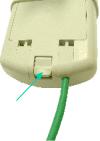
Module Description
The base cover of your Canopy Backhaul is easily removed by depressing the release lever on the back of the cover.
|
Base Cover |
Base Cover |
|
Release |
Ethernet |
|
|
Lever |
Cable |
|
|
|
|
FIGURE 1
Backhaul User Manual Issue 3 |
Page 9 of 53 |
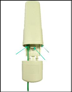
Remove the base cover as shown in FIGURE 1 to access the Ethernet connection and the Connection LED alignment indicators.
♦The RJ-45 connector is used to attach the Ethernet cable
♦The RJ-11 connector is used to attach the GPS sync cable
♦The LED’s indicate system status and are used for alignment.
Canopy B
RJ11
RJ45 Connector
Connector
Connection
LEDs
Base Cover
Ethernet
Cable
FIGURE 2
The diagnostic LEDs report information about the current status of the access point module. The following descriptions explain the function of each LED.
Operational Mode
LNK: The link LED displays the status of the Ethernet link to the Canopy module. The LED will be constantly lit if there is an Ethernet link present. The LED is colored green.
ACT/4: The activity LED displays the status of any data activity on the Ethernet link. The LED will flash (at no particular speed) when data is being transferred on the Ethernet link. The LED is colored orange.
GPS/3: If the module is a backhaul timing master the GPS LED displays the status of the sync pulse and is lit constantly when the pulse is being received. If the module is a backhaul timing slave this LED is not utilized. The LED is red.
SES/2: The session LED is not used on the access point module. The LED is green.
SYN/1: The sync LED displays sync status. In short, this LED will lit all the time on an access point module. The LED is orange.
Backhaul User Manual Issue 3 |
Page 10 of 53 |
PWR: The power LED displays the status of power to the module. The LED will be constantly lit if power is applied correctly. The LED is red.
If the module is a backhaul timing slave and is not registered to a backhaul timing master then the SYN/1, SES/2, and GPS/3 LEDs will cycle on and off from left to right.
Alignment Mode
When a backhaul timing slave module is placed in Alignment Mode the LEDs take on an entirely different purpose. The power LED will still indicate whether or not power is applied to the module. The 6 LEDs and are turned into a 6-position bar graph. The more LEDs that are lit, the better the RSSI and Jitter values the module is seeing. The colors of the LEDS have no particular meaning other than to assist is distinguishing one position from the next. See Alignment section for more information.
Backhaul User Manual Issue 3 |
Page 11 of 53 |
BACKGROUND INFORMATION ON NETWORKING
Computers are assigned IP addresses by network operators, which have two methods available, static or dynamic IP addressing. The user of this document will need to understand how IP addressing is done at their particular location.
All Canopy radio products (Subscriber Modules, Access Point Modules, and Backhaul Modules) have the default IP address of 169.254.1.1. For a computer to talk to Canopy, as it comes from the factory, either of the following conditions must be met:
•If the computer is not configured for DHCP, then it has to have a static IP address on the 169.254 network (i.e. 169.254.1.5)
•If the computer is configured for DHCP, then it will automatically obtain an IP address on the 169.254 network after minute or two as long as it is not connected to the network.
Backhaul User Manual Issue 3 |
Page 12 of 53 |
SYSTEM OVERVIEW AND SITE PLANNING
Definitions:
Backhaul Timing Master – a module that is used in a point-to-point link. This module controls the air protocol and configurations for the link.
Backhaul Timing Slave – a module that is used in a point-to-point link. This module accepts configuration from the master module.
Cluster Management Module – a module that contains power, GPS timing, and networking for backhaul timing master(s). Can also be utilized in conjunction with an access point cluster.
In the Canopy System, the point-to-point link is achieved utilizing backhaul modules in either the 5.2 GHz or 5.7 GHz band. The backhaul modules utilize passive reflector to achieve distances of up to 35 miles (56 km). Note: Distances may vary based on terrain and other line of sight issues.
In its basic form the point-to-point link is made up of a backhaul timing master and a backhaul timing slave. The cluster management module is key to the operation of the Canopy System. Backhaul timing masters must be connected to a cluster management module so that a GPS timing pulse can synchronize their transmission cycles. If one backhaul timing master module were to not be synchronized then it may be transmitting during a receive cycle of the other modules and cause de-sense. This is also true of the Canopy access point modules.
The following are some simple network diagrams of the proper way to layout single and multihopped point-to-point links.
Example 1: The single hop.
Canopy |
Canopy |
Backhaul |
Backhaul |
Master |
Slave |
Example 2: The multiple hop with the backhaul master modules at the ends of the link.
Backhaul User Manual Issue 3 |
Page 13 of 53 |

CMM |
Canopy |
CMM |
|
|
|
|
Backhaul |
|
|
|
|
Canopy |
Slaves |
Canopy |
|
|
Backhaul |
Backhaul |
|
Master |
||
Master |
||
|
Example 3: The multiple hop with the backhaul master modules in the middle of the link.
Canopy |
CMM |
Canopy |
|
Backhaul |
|
||
|
Backhaul |
||
Slave |
|
||
Canopy |
Slave |
||
|
Backhaul
Masters
From these diagrams it can be seen that at each location there is only like kind backhaul modules. In all cases where there is a cluster management module an access point cluster could be placed also. In the case of Example 2, a cluster management module could be placed where the two backhaul timing slaves are located to install an access point cluster; however the timing slaves do not need to be connected to he CMM for timing purposes.
Site Selection Criteria
There are various issues that need to be taken into consideration when choosing a location for the network infrastructure. The following is a list of those considerations. There may be others as each site is unique.
•Height is essential when installing a Canopy backhaul module. The Canopy backhaul module must be mounted higher than other objects located immediately around it such as trees, buildings, tower legs, etc.
•There should be no obstructions that will interfere with the unit’s internal antenna. The area immediately in front of an access point module must be clear of all obstructions.
•Will the installation area change in the future? Will there be structures high enough to
Backhaul User Manual Issue 3 |
Page 14 of 53 |
interfere with the signal? Will trees grow into the line-of-sight path?
•When possible, avoid high RF energy sites. Do not place Canopy equipment in the same plane as other RF equipment.
•The means used by the installer to attach the backhaul module to the tower, rooftop, or pole should be rigid and should not move or flex due to wind or other vibrations.
•Tower availability - will a tower have to erected?
•There must be grounding systems available for protection of the Canopy equipment.
•Lighting arrestors are required in installation area to transport lightning strikes away from equipment.
Backhaul User Manual Issue 3 |
Page 15 of 53 |
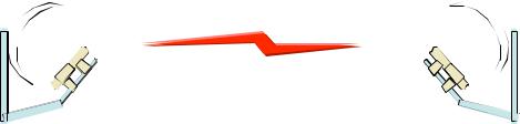
General Considerations
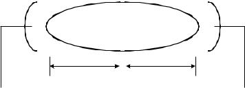
•Fresnel Loss - The Fresnel Zone is a theoretical area around the line of sight of an antenna transmission that can affect the signal strength. Objects that penetrate the Fresnel Zone can cause fading of the transmitted signal. This fading is caused by the cancellation of the signal due to out-of-phase reflections. An unobstructed line of sight is important, but it is not the only determination of an adequate placement. Even though the path has a clear line of sight, if obstructions (such as terrain, vegetation, metal roofs, cars, etc.) penetrate the Fresnel zone, there will be signal loss. The following illustrates a Fresnel zone.
Fresnel Zone
|
D1 |
D2 |
|
|
|
|
|
Transmitter |
|
|
Receiver |
|
|
|
|
•Free Space Path Loss – As an RF signal travels through space, it is attenuated by the distance from the initial transmission point. The farther away from the transmission point, the weaker the RF signal.
•Foliage Loss – Tree and plant foliage will cause additional signal loss. Seasonal density, moisture content of the foliage, and other factors such as wind may change the amount of loss. Caution should be used when a link may transmit though this type of environment.
•Carrier to Interference – describes how much signal advantage must be engineered into the radio link to tolerate an interfering transmission.
•How many point-to-point links are being planned for deployment? Each backhaul timing master will need to utilize a cluster management module for seamless operation within the entire Canopy System.
•How will the access point clusters be deployed relative to planned point-to-point links?
Backhaul User Manual Issue 3 |
Page 16 of 53 |
 Loading...