


 Loading...
CP200XLSTM
Commercial Series
Two-Way Radio User Guide
Manuel de l’utilisateur
de la radio bidirectionnelle

CONTENTS
Computer Software
Copyrights . . . . . . . . . . . . . . . . . . . . . . . . . . v Safety . . . . . . . . . . . . . . . . . . . . . . . . . . . . . . vi
Product Safety and RF Exposure
Compliance . . . . . . . . . . . . . . . . . . . . . . . . . vi
Introduction . . . . . . . . . . . . . . . . . . . . . . . . . 1
Conventional Radio Systems . . . . . . . . . . . . 1 Trunked Radio Systems . . . . . . . . . . . . . . . . 1 LTR Trunked Systems . . . . . . . . . . . . . . . 1 CP200XLS Radio Features. . . . . . . . . . . . . . 2 Radio-Wide Features . . . . . . . . . . . . . . . . 2 LTR Trunked Features. . . . . . . . . . . . . . . 2 Conventional Signaling Features . . . . . . . 2
Radio Overview . . . . . . . . . . . . . . . . . . . . . . 3
Full Keypad Radio Overview. . . . . . . . . . . . . 3 Limited Keypad Radio Overview . . . . . . . . . . 4 Accessory Information. . . . . . . . . . . . . . . . . . 5 Attach the Battery . . . . . . . . . . . . . . . . . . 5 Remove the Battery . . . . . . . . . . . . . . . . . 5 Attach the Antenna . . . . . . . . . . . . . . . . . 6 Remove the Antenna . . . . . . . . . . . . . . . . 6 Attach the Belt Clip . . . . . . . . . . . . . . . . . 7
Remove the Belt Clip. . . . . . . . . . . . . . . . .7 Battery Information . . . . . . . . . . . . . . . . . . . . .8 Charging Your Battery. . . . . . . . . . . . . . . . 8 Wall Charger. . . . . . . . . . . . . . . . . . . . . . . . . .9 Desktop Chargers. . . . . . . . . . . . . . . . . . . . . . 9 Rapid Charger . . . . . . . . . . . . . . . . . . . . . .9 Slow Charger. . . . . . . . . . . . . . . . . . . . . .10 Battery Charge Status . . . . . . . . . . . . . . . . .11 LED Indicator . . . . . . . . . . . . . . . . . . . . . . . . 11 Display . . . . . . . . . . . . . . . . . . . . . . . . . . . . .12
DTMF Keypad (Full Keypad
Model Only) . . . . . . . . . . . . . . . . . . . . . . . .13 Indicator Tones. . . . . . . . . . . . . . . . . . . . . . . 14 Programmable Buttons. . . . . . . . . . . . . . . . . 15 Menu Buttons . . . . . . . . . . . . . . . . . . . . . . . .19 Menu Button . . . . . . . . . . . . . . . . . . . . . .19 Menu Scroll Buttons . . . . . . . . . . . . . . . .19 Navigate the Menu . . . . . . . . . . . . . . . . .19 Exit the Menu . . . . . . . . . . . . . . . . . . . . .19
Getting Started . . . . . . . . . . . . . . . . . . . . . .20
Turn the Radio On or Off . . . . . . . . . . . . . . . 20 Adjust the Volume . . . . . . . . . . . . . . . . . . . .21 Select an LTR Channel/Talkgroup . . . . . . . . 21 Select a Conventional Radio Channel . . . . . 22 Receive a Conventional or LTR Call . . . . . .22 Monitor . . . . . . . . . . . . . . . . . . . . . . . . . . . . .22
i
CONTENTS
English

CONTENTS
Permanent Monitor . . . . . . . . . . . . . . . . .23 Transmit an LTR Call . . . . . . . . . . . . . . . . . .23 Transmit a Conventional
Call . . . . . . . . . . . . . . . . . . . . . . . . . . . . . .24 Call Light
(Trunked Operation Only). . . . . . . . . . . . . .24 Repeater or Talkaround J Mode. . . . . . . .24 Revert Memory Channel (1 & 2). . . . . . . . . .25 Store Memory Channel (1 & 2). . . . . . . . . . .25 Home Revert Autokey (1 & 2). . . . . . . . . . . .26 VOX Operation . . . . . . . . . . . . . . . . . . . . . . .26
Connecting a VOX Headset . . . . . . . . . .26 Enable or Disable VOX . . . . . . . . . . . . . .26 Enable/Disable Headset Sidetone . . . . . . . .26 VOX Headset. . . . . . . . . . . . . . . . . . . . . .26
Non-VOX Headset with
In-Line PTT. . . . . . . . . . . . . . . . . . . . . .27 Keypad Lock/Unlock L . . . . . . . . . . . . . . . .27 Program PL/DPL Codes . . . . . . . . . . . . . . . .27
Radio Calls . . . . . . . . . . . . . . . . . . . . . . . . .29
Selective Radio Inhibit . . . . . . . . . . . . . . . . .29 Receive a Selective Call F
(Conventional Operation Only) . . . . . . . . . .29 Send a Selective Call
(Conventional Operation Only) . . . . . . . . . .29
Receive a Call Alert™ Page F
(Conventional Operation Only). . . . . . . . . . . 30
Send a Call Alert Page
(Conventional Operation Only). . . . . . . . . . . 30
Repeater Access (Full
Keypad Model Only). . . . . . . . . . . . . . . . . . . 31
Radio Check (Full Keypad
Model Only) . . . . . . . . . . . . . . . . . . . . . . . . . 31
Scan. . . . . . . . . . . . . . . . . . . . . . . . . . . . . . . 32
Talkback. . . . . . . . . . . . . . . . . . . . . . . . . . . . 32 Start System Scan G. . . . . . . . . . . . . . . . 32 Stop System Scan . . . . . . . . . . . . . . . . . . . . 33 Start Auto Scan G. . . . . . . . . . . . . . . . . . 33 Stop Auto Scan . . . . . . . . . . . . . . . . . . . . . . 33 Delete a Nuisance Channel
/Talkgroup . . . . . . . . . . . . . . . . . . . . . . . . . . 34 Restore Channels/Talkgroups
to the Scan List. . . . . . . . . . . . . . . . . . . . 34 Edit a Scan List . . . . . . . . . . . . . . . . . . . . . . 35 Add or Delete Channels/Talkgroups
in a Scan List . . . . . . . . . . . . . . . . . . . . . . . . 35 Prioritize a Channel or Talkgroup
in a Scan List . . . . . . . . . . . . . . . . . . . . . . . . 36
ii
English

Phone . . . . . . . . . . . . . . . . . . . . . . . . . . . . . 38
Access the Repeater. . . . . . . . . . . . . . . . . . 38
Receive a Phone Call D. . . . . . . . . . . . . . . 38
Disconnect a Phone Call. . . . . . . . . . . . . . . 39
Make a Phone Call D. . . . . . . . . . . . . . . . . 39
Edit the Phone List (Full Keypad
Model Only). . . . . . . . . . . . . . . . . . . . . . . . . 40
Add an Entry . . . . . . . . . . . . . . . . . . . . . 41
Delete an Entry . . . . . . . . . . . . . . . . . . . 41
Edit an Entry . . . . . . . . . . . . . . . . . . . . . 42
Edit Access/Deaccess Codes . . . . . . . . 43
Tone Preferences . . . . . . . . . . . . . . . . . . . 44
Tones On/Off. . . . . . . . . . . . . . . . . . . . . . . . 46
Keypad On/Off Tones . . . . . . . . . . . . . . . . . 46
Call Tone Tagging
(Conventional
Operation Only). . . . . . . . . . . . . . . . . . . . . . 46
Escalert
(Conventional
Operation Only). . . . . . . . . . . . . . . . . . . . . 47
User Settings. . . . . . . . . . . . . . . . . . . . . . . 48
Set Squelch Level . . . . . . . . . . . . . . . . . . . . 50
Set Power Level B. . . . . . . . . . . . . . . . . . . 50
Set the Lights . . . . . . . . . . . . . . . . . . . . . . . 51
Display the Software Version . . . . . . . . . . . 51
Warranty . . . . . . . . . . . . . . . . . . . . . . . . . . .52
Limited Warranty
Motorola Communication
Products . . . . . . . . . . . . . . . . . . . . . . . . . . . .52
Accessories . . . . . . . . . . . . . . . . . . . . . . . .56
Antennas . . . . . . . . . . . . . . . . . . . . . . . . . . .56
Batteries . . . . . . . . . . . . . . . . . . . . . . . . . . . . 56
Carry Accessories . . . . . . . . . . . . . . . . . . . . 56
Chargers. . . . . . . . . . . . . . . . . . . . . . . . . . . .56
Headsets . . . . . . . . . . . . . . . . . . . . . . . . . . .57
Surveillance Accessories . . . . . . . . . . . . . . .57
Ear Microphone Systems . . . . . . . . . . . . . . .58
Remote Speaker Microphones . . . . . . . . . . . 58
Miscellaneous. . . . . . . . . . . . . . . . . . . . . . . .58
iii
CONTENTS
English

Notes
CONTENTS
iv
English

COMPUTER SOFTWARE COPYRIGHTS
The Motorola products described in this manual may include copyrighted Motorola computer programs stored in semiconductor memories or other media. Laws in the United States and other countries preserve for Motorola certain exclusive rights for copyrighted computer programs, including, but not limited to, the exclusive right to copy or reproduce in any form the copyrighted computer program. Accordingly, any copyrighted Motorola computer programs contained in the Motorola products described in this manual may not be copied, reproduced, modified, reverse-engineered, or distributed in any manner without the express written permission of Motorola.
Furthermore, the purchase of Motorola products shall not be deemed to grant either directly or by implication, estoppel, or otherwise, any license under the copyrights, patents or patent applications of Motorola, except for the normal non-exclusive license to use that arises by operation of law in the sale of a product.
v
SOFTWARE COMPUTER COPYRIGHTS
English

SAFETY
SAFETY
PRODUCT SAFETY AND RF EXPOSURE COMPLIANCE
!
C a u t i o n
Before using this product, read the operating instructions for safe usage contained in the Product Safety and RF Exposure booklet enclosed with your radio.
ATTENTION!
This radio is restricted to occupational use only to satisfy FCC RF energy exposure requirements. Before using this product, read the RF energy awareness information and operating instructions in the Quick Reference Guide/Safety booklet enclosed with your radio (Motorola Publication part number 68009327001_) to ensure compliance with RF energy exposure limits.
For a list of Motorola-approved antennas, batteries, and other accessories, visit the following web site which lists approved accessories: www.motorola.com/business and browse the accessory section.
vi
English

INTRODUCTION
Your CP200XLS™ radio can operate on both LTR® trunked and conventional radio systems. This radio combines the very latest in two-way technology while delivering outstanding functionality at the touch of a button.
CONVENTIONAL RADIO SYSTEMS
Conventional typically refers to radio-to-radio communications through a single channel. Conventional systems also allow radio users to extend communication coverage by relaying their messages through a repeater. To ensure coordinated use by multiple users, each radio user must monitor the channel or repeater before transmitting to verify that the system is not currently busy.
TRUNKED RADIO SYSTEMS
A trunked radio system allows a large number of users to share a relatively small number of frequencies or repeaters without interfering with each other. The airtime of all the repeaters in a trunked system is pooled, which maximizes the amount of airtime available to any one radio and minimizes channel/ talkgroup congestion.
Some of the benefits of trunked two-way radio systems are:
•No channel/talkgroup monitoring required prior to transmission
•Improved system access
•Automatic channel/talkgroup selection
•Increased privacy among members of the same group
LTR Trunked Systems
LTR (Logic Trunked Radio) is a transmissionbased trunking protocol developed by the E. F. Johnson Company for primarily single-site trunking applications. In transmission trunking, a repeater is used for only the duration of a single transmission. Once a transmission is completed, that repeater becomes available to other users. This means that a conversation comprised of many transmissions may occur over several different channels/talkgroups within the LTR system. This method of trunking provides system efficiency by making repeaters available to all users after every transmission.
1
INTRODUCTION
English

INTRODUCTION
When an LTR trunked radio user wants to communicate with another radio, the user’s radio sends a “channel/talkgroup request” to the home repeater. The system then sends back a “channel/talkgroup grant” to the user’s radio. The channel/talkgroup grant message contains the number of a “go to” repeater to tell the radio which repeater to use. This “go to” repeater can be the same as the radio’s home repeater or another repeater in the system. The radio uses the “go to” repeater for transmission. Once the transmission has ended, this repeater is available for other users.
CP200XLS RADIO FEATURES
Radio-Wide Features
•128 Conventional Channels
•Up to 10 Sites and 100 Talkgroups
•Up to 20 Repeaters per Site
•8-Character Alphanumeric Display
•4 Programmable Feature Buttons
•2 Memory Channels
•Telephone Interconnect
•User-programmable Phone (Full Keypad Model only), Scan, and TPL/DPL Lists
•Busy Channel Lockout
2
•High/Low Power Settings
•Transmit Time-Out Timer
•Monitor and Sticky Permanent Monitor
•System Scan with 2 Priority Levels and Revert Scan
LTR Trunked Features
•MDC 1200 Signaling
|
- |
Selective Radio |
- |
MDC Pre-Time |
|
|
Inhibit Decode |
- |
PTT ID Encode/ |
|
- |
Radio Check |
|
Decode |
|
|
Decode |
- |
DOS |
|
|
|
||
Conventional Signaling Features |
||||
• |
MDC 1200 Signaling |
|
|
|
|
- |
Selective Radio |
- |
PTT ID Encode/ |
|
|
Inhibit Decode |
|
Decode |
|
|
|
|
|
• Quik-Call II Signaling |
|
|
||
|
- |
Call Alert Encode/ |
- |
Radio Call List |
|
|
Decode |
- |
Call Tone |
|
- |
Selective Call |
|
Tagging |
|
|
Encode/Decode |
|
|
|
|
|
|
|
• |
DTMF Signaling |
|
|
|
|
- |
DTMF PTT ID |
- |
DTMF |
|
|
Encode |
|
Selective Call |
|
- |
DTMF Call Alert |
|
Encode |
|
|
Encode |
|
|
|
|
|
|
|
English
RADIO OVERVIEW
FULL KEYPAD RADIO OVERVIEW
Antenna
Push-to-Talk
(PTT) Button
Side Button 1 (programmable) 
Side Button 2 (programmable) 
Front Button 1  (programmable)
ON/OFF/Volume
Knob
 Channel Selector
Knob
 LED Indicator
Microphone/
Speaker
Display
Front Button 2 (programmable)
DTMF Keypad
Accessory Connector with a Dust Cover
Belt
Clip
3
OVERVIEW RADIO
English

RADIO OVERVIEW
LIMITED KEYPAD RADIO OVERVIEW
Antenna
Push-to-Talk
(PTT) Button
Side Button 1 (programmable) 
Side Button 2 (programmable) 
Front Button 1  (programmable)
ON/OFF/Volume
Knob
 Channel Selector
Knob
 LED Indicator
Microphone/
Speaker
Display
Front Button 2 (programmable)
DTMF Keypad
Accessory Connector with a Dust Cover
4
Belt
Clip
English
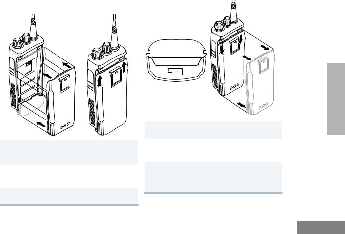
ACCESSORY INFORMATION |
Remove the Battery |
Attach the Battery |
|
1Align the battery to the battery rails on the back of the radio (approximately 1/2 inch from the top of the radio.)
2Press the battery firmly to the radio and slide the battery upward until the latch snaps into place.
3Slide the battery latch, located on radio bottom, into the lock position.
Locked
Unlocked
Battery Latch
1Turn OFF the radio if it is turned ON (see page 20).
2Slide the battery latch into the unlock position. Disengage by pushing downward and holding the latch towards the front of the radio.
3With the battery latch disengaged, slide the battery down from the top of the radio about 1/2 inch. Once the battery is free from the battery rails, lift it directly away from the radio.
5
OVERVIEW RADIO
English
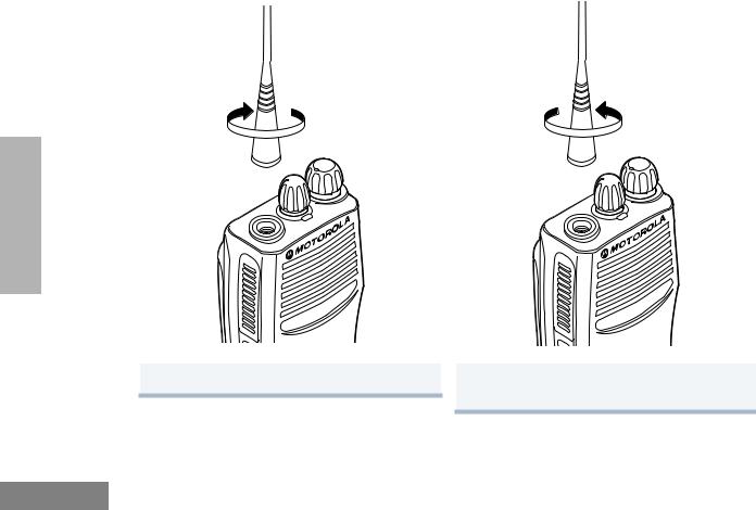
Attach the Antenna |
Remove the Antenna |
RADIO OVERVIEW
Turn the antenna clockwise to attach it.
Turn the antenna counterclockwise to remove it.
6
English

Attach the Belt Clip |
Remove the Belt Clip |
Belt Clip Tab
OVERVIEW RADIO
1 |
Align the grooves of the belt clip with those of |
1 |
Use a key to press the belt clip tab away from |
|
the battery. |
|
the battery to unlock the belt clip. |
2 |
Press the belt clip downward until you hear a |
2 |
Slide the belt clip upward to remove it. |
|
click. |
|
|
|
|
|
7 |
English

RADIO OVERVIEW
BATTERY INFORMATION
Charging Your Battery
This radio is powered by a nickel-cadmium (NICd), a nickel-metal hydride (NiMH), or a lithium-ion (Li-lon) rechargeable battery.
Charge the battery before use to ensure optimum capacity and performance. The battery was designed specifically to be used with a Motorola charger. Charging in nonMotorola equipment may lead to battery damage and void the battery warranty.
Note: When charging a battery attached to a radio, turn the radio OFF to ensure a full charge.
The battery should be at about 77°F (25°C) (room temperature), whenever possible. Charging a cold battery (below 50° F [10°C]) may result in leakage of electrolyte and ultimately in failure of the battery. Charging a hot battery (above 95°F [35°C]) results in reduced discharge capacity, affecting the performance of the radio. Motorola rapid-rate battery chargers contain a temperaturesensing circuit to ensure that batteries are charged within the temperature limits stated above.
8
If a battery is new, or its charge level is very low, you will need to charge it before you can use it. When the battery level is low and the radio is in transmit mode you will see the LED indicator blink red. Upon release of the PTT button, you will hear an alert tone.
Note: Batteries are shipped uncharged from the factory. Always charge a new battery 14 to 16 hours before initial use, regardless of the status indicated by the charger.
Note: Do not use the wall charger and desktop charger at the same time when charging.
English

WALL CHARGER
Note: Do not use the wall charger if using lithiumion (Li-Ion) or nickel-metal hydride (NiMH) batteries. The wall charger is for a nickelcadmium (NiCd) battery only.
To Charge the Battery:
1Turn the radio OFF.
2Lift the dust cover to expose the audio accessory connector.
3Insert the charging adapter into the accessory connector.
4Plug the charging adapter into an electrical outlet.
•The LED on the charging adapter lights red while the charger is plugged into an electrical outlet.
Note: Do not leave the charger connected to the radio when it is not connected to the electrical outlet.
5Unplug the charger from the electrical outlet and radio after 10 hours.
Note: After the initial charge of 14 to 16 hours, do not charge the battery more than 10 hours.
DESKTOP CHARGERS
Rapid Charger
1Turn the radio OFF.
2Place the battery, with or without the radio, in the charger pocket.
•The charger LED indicates the charging progress.
LED color |
Status |
No LED Indication |
Battery inserted incorrectly |
|
or battery not detected. |
Single Green Blink |
Successful charger |
|
power-up. |
|
|
Blinking Reda |
Battery unchargeable or not |
|
making proper contact. |
|
|
Steady Red |
Battery is in Rapid charge |
|
mode. |
|
|
|
9 |
OVERVIEW RADIO
English

RADIO OVERVIEW
LED color |
Status |
Blinking Yellow |
Battery in charger but |
|
waiting to be charged. The |
|
battery temperature may be |
|
too hot or too cold. The |
|
voltage may be lower than |
|
the predetermined threshold |
|
level for charging. |
|
|
Blinking Greenb |
Battery 90% (or more) |
|
charged. Trickle charging. |
|
|
Green |
Battery fully charged. |
a.Remove the battery from the charger and use a pencil eraser to clean the three metal contacts at the back of the battery. Place the battery back into the charger. If the LED indicator continues to blink red, replace the battery.
b.A standard battery may require 90 minutes to charge to 90% capacity. Even though new batteries might prematurely indicate a full charge (steady green LED), charge the battery for 14 to 16 hours prior to initial use for best performance.
10
A list of Motorola authorized batteries and battery chargers appears on page 56. The listed chargers will charge only Motorola authorized batteries. Other batteries may not charge.
Slow Charger
Note: Do not use the slow charger if using lithiumion (Li-Ion) or nickel-metal hydride (NiMH) batteries. The slow charger is for a nickelcadmium (NiCd) battery only.
1Turn the radio OFF.
2Place the battery, with or without the radio, in the charger pocket.
•The charger LED indicates the charging progress.
LED color |
Status |
No LED Indication |
Battery inserted incorrectly |
|
or battery not detected. |
|
|
Steady Red |
Battery is in over night |
|
charge mode. The battery is |
|
fully charged after 11 hours. |
|
|
English

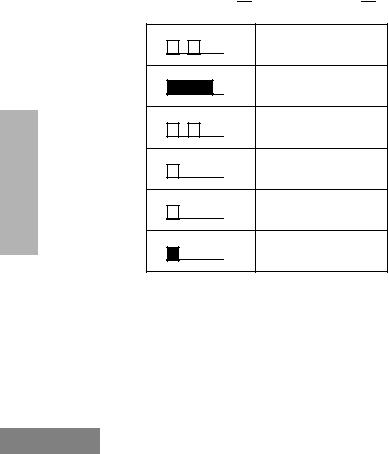
BATTERY CHARGE STATUS
You can check battery charge status if your dealer has preprogrammed one of the programmable buttons. Hold down the preprogrammed Battery Indicator button. The charge status is shown on the display.
Battery |
Display |
|
Level |
||
|
Full
Good
Fair
Low
Very Low
LED INDICATOR
Indicates power-up, transmit, receive, scan monitor status, channel/talkgroup busy, Call Alert™ receive/transmit, Selective Call receive/ transmit, and battery status.
LED State/Color |
Indication |
|
|
|
Radio Call |
|
|
|
|
Red |
Transmitting |
|
|
|
Blinking Red |
Receiving |
|
|
|
RADIO |
||||
Blinking Red |
Channel/Talkgroup Busy |
|
||
Scan |
|
|
||
Blinking Green |
Scanning for activity |
|
||
|
|
|
OVERVIEW |
|
Call Alert |
|
|
||
Blinking Yellow |
Indicates receiving a Call Alert |
|
|
|
Yellow |
Indicates sending a Call Alert |
|
|
|
Selective Call |
|
|
|
|
Blinking Yellow |
Indicates receiving a Selective |
|
|
|
|
Call |
|
|
|
|
|
|||
Yellow |
Indicates sending a Selective |
|
|
|
|
Call |
|
|
|
Monitor/Open Squelch |
|
|
||
Yellow |
While monitoring |
|
|
|
Low Battery |
|
|
|
|
Blinking Red |
Low battery level |
|
|
|
when transmitting |
|
|
|
|
|
11 |
|
|
|
English

DISPLAY
PERS4
The top display row displays menu and radio status information:
|
|
Symbol |
Indication |
|
|
|
|
OVERVIEW |
|
|
|
|
I |
The more bars, the stronger |
|
|
B |
Low Power “R” or High Power |
|
|
|
|
the signal being received by |
|
|
Signal Strength |
your radio. |
RADIO |
|
Power Level |
“S” is activated. |
|
|
||
|
|
|
|
|
C |
The selected channel is being |
|
|
|
Monitor |
monitored. |
|
|
|
|
|
|
|
|
|
|
D |
Phone mode is selected. |
|
|
Phone |
|
|
|
|
|
|
|
G |
Indicates that the Scan |
|
|
Scan |
feature has been activated. |
|
|
|
|
|
|
|
|
|
12 |
|
|
Symbol |
Indication |
|
|
|
|
H |
Indicates scan has stopped |
|
•Priority 1 Scan |
on an active Priority 1 |
|
channel/talkgroup. |
||
(• Blinking) |
|
|
H |
Indicates scan has stopped |
|
Priority 2 Scan |
on an active Priority 2 |
|
channel/talkgroup. |
||
(• Steady) |
||
|
||
|
|
|
J |
Bypass the repeater and talk |
|
Talkaround |
directly to another radio. |
|
|
||
|
|
|
F |
A Selective Call or Call Alert |
|
Call Received |
has been received. |
|
|
||
|
|
|
B |
Not Used. |
|
|
|
|
L |
The keypad has been locked. |
|
Keypad Lock |
|
|
|
|
English
DTMF KEYPAD (FULL KEYPAD MODEL ONLY)
*
The keypad is used for:
•Dialing a phone number.
•Entering information when programming phone lists.
•Accessing a repeater.
•Each key can generate several different characters. For example, to enter the character “C,” press the 2button three times. (Refer to the following table.)
Entering Characters Using the
DTMF Keypad
Number of Times Button is Pressed |
|
|
|
||||
|
|
|
|
|
|
|
|
Button |
1 |
2 |
3 |
4 |
5 |
|
|
|
|
|
|
|
|
|
|
0 |
0 |
|
|
|
|
|
|
1 |
1 |
/ |
\ |
|
|
|
|
|
|
|
|
|
|
|
|
2 |
A |
B |
C |
2 |
|
|
|
3 |
D |
E |
F |
3 |
|
|
|
|
|
RADIO |
|||||
|
|
|
|
|
|
|
|
4 |
G |
H |
I |
4 |
|
|
|
|
|
|
|||||
5 |
J |
K |
L |
5 |
|
|
OVERVIEW |
|
|
|
|
|
|
|
|
6 |
M |
N |
O |
6 |
|
|
|
|
|
|
|||||
7 |
P |
Q |
R |
S |
7 |
|
|
|
|
|
|
|
|
|
|
8 |
T |
U |
V |
8 |
|
|
|
9 |
W |
X |
Y |
Z |
9 |
|
|
|
|||||||
|
|
|
|
|
|
|
|
* |
* |
< |
> |
|
|
|
|
# |
# |
+ |
- |
_ |
|
|
|
|
|
|
|
|
|
|
|
13
English
RADIO OVERVIEW
INDICATOR TONES
High pitched tone  Low pitched tone

Self Test Pass Tone
Self Test Fail Tone
Positive Indicator Tone
Negative Indicator
Tone
Good Key Tone
Bad Key Tone
Some programmable buttons use tones to indicate one of two modes:
14
|
Positive |
Negative |
ProgrammableButton |
Indicator |
Indicator |
s |
Tone |
Tone |
Scan |
Start |
Stop |
Power Level |
High |
Low |
|
|
|
Squelch |
Tight |
Normal |
|
|
|
Repeater/Talkaround |
Does not |
Uses |
|
use repeater |
repeater |
VOX |
Enabled |
Disabled |
Silent Monitor/Open |
— |
Enabled |
Squelch |
|
|
|
|
|
Revert Memory |
— |
Enabled |
Channel (1&2) |
|
|
|
|
|
Store Memory |
— |
Stored |
Channel (1&2) |
|
|
Home Revert AutoKey |
— |
Enabled |
(1&2) |
|
|
|
|
|
Menu Mode J |
— |
Accessed |
|
|
|
Radio Call |
— |
Enabled |
|
|
|
Scan List Edit |
— |
Enabled |
|
|
|
Speed Dial (Full |
— |
Enabled |
Keypad Model Only) |
|
|
|
|
|
Phone Mode |
— |
Enabled |
|
|
|
Escalert |
Enabled |
Disabled |
|
|
|
English

PROGRAMMABLE BUTTONS
Your radio has four programmable buttons. Your dealer can program these buttons as shortcuts to various radio features.
Check with your dealer for a complete list of functions your radio supports.
Programmable buttons include:
•The two side buttons (S1 and S2)
•The two front buttons (Kand J)
Some buttons can access up to two features, depending on the type of button press:
•Short Press — quickly pressing and releasing the programmable buttons.
•Long Press — pressing and holding the programmable buttons for a minimum of 2.5 seconds.
•Hold Down — pressing and holding down the programmable buttons while checking status or making adjustments.
The table on page 16 summarizes the programmable features available and shows the page number where the feature is explained.
In the “Button” column, have your dealer record the name of the programmable button next to the feature that has been programmed to it.
The dealer can use the abbreviations (S1, S2, P1, or P2) shown in the radio illustration on page 3.
Also, where appropriate, have your dealer indicate whether the button press requires a short press, a long press, or needs to be held down.
15
OVERVIEW RADIO
English

RADIO OVERVIEW
Programmable Features
Feature |
Indicator |
Short Press |
|
Long Press |
Hold Down |
Page |
Button |
|
|
|
|
|
|
|
|
Battery |
|
— |
|
— |
Checks the |
11 |
|
Indicator |
|
|
|
|
battery charge |
|
|
|
|
|
|
|
status. |
|
|
|
|
|
|
|
|
|
|
Menu Mode |
— |
Jbutton enters Menu Mode and |
— |
19 |
J |
||
|
|
selects menu options. Once in Menu |
|
|
|
||
|
|
Mode, Kbutton is automatically |
|
|
|
||
|
|
re-assigned to exit Menu Mode.† |
|
|
|
||
Volume Set |
— |
— |
|
— |
Sounds a tone |
21 |
|
|
|
|
|
|
for adjusting the |
|
|
|
|
|
|
|
radio’s volume |
|
|
|
|
|
|
|
level. |
|
|
|
|
|
|
|
|
|
|
Monitor |
C |
A long press initiates Monitor. A short |
Monitors the |
22 |
|
||
|
|
press cancels Monitor. |
|
selected |
|
|
|
|
|
|
|
|
channel for any |
|
|
|
|
|
|
|
activity. |
|
|
|
|
|
|
|
|
||
Repeater/Talkaround |
J |
Toggles between using a repeater or |
— |
24 |
|
||
|
|
transmitting directly to another radio.† |
|
|
|
||
Revert Memory |
— |
Allows instant |
|
— |
— |
25 |
|
Channel (1&2) |
|
access to the |
|
|
|
|
|
|
|
home channel/ |
|
|
|
|
|
|
|
talkgroup. |
|
|
|
|
|
|
|
|
|
|
|
|
|
†This function is activated by EITHER a short OR a long press, but not both.
16
English

Programmable Features (Continued)
Feature |
Indicator |
Short Press |
Long Press |
Hold Down |
Page |
Button |
|
|
|
|
|
|
|
|
|
|
|
Store Memory |
— |
|
Stores current |
— |
25 |
|
|
|
Channel (1&2) |
|
|
channel/talkgroup |
|
|
|
|
|
|
|
|
to the home |
|
|
|
|
|
|
|
|
channel/talkgroup. |
|
|
|
|
|
|
|
|
|
|
|
|
|
|
Home Revert AutoKey |
— |
If a Revert Memory Channel is an LTR |
— |
26 |
|
|
|
|
(1&2) |
|
talkgroup, the radio keys-up and |
|
|
|
|
|
|
|
|
transmits an MDC PTT ID. If a Revert |
|
|
|
|
|
|
|
|
|
|
|
|
RADIO |
||
Voice Operated |
— |
Memory Channel is a conventional |
— |
26 |
|
|
||
Toggle VOX ON and OFF.† |
|
|
||||||
|
|
channel, it does not key-up.† |
|
|
|
|
|
|
Transmission (VOX) |
|
|
|
|
|
|
|
OVERVIEW |
|
|
|
|
|
|
|
|
|
|
|
|
|
|
|
|
|
|
Keypad Lock/Unlock |
L |
|
Toggle keypad |
|
27 |
|
|
|
|
|
|
between locked |
|
|
|
|
|
|
|
|
and unlocked. |
|
|
|
|
|
|
|
|
|
|
|
|
|
|
Radio Call |
— |
Directly access radio |
call menu.† |
— |
29,30 |
|
|
|
|
|
|
|
|
|
|
|
|
Scan/Nuisance |
G |
Starts or stops the |
Deletes a nuisance |
— |
32,33 |
|
|
|
Channel/Talkgroup |
|
Scan operation. |
channel/talkgroup |
|
|
|
|
|
Delete |
|
|
while scanning. |
|
|
|
|
|
|
|
|
|
|
|
|
|
|
Edit Scan List |
— |
Add, delete, or prioritize channels/ |
— |
35 |
|
|
|
|
|
|
talkgroups.† |
|
|
|
|
|
|
† This function is activated by EITHER a short OR a long press, but not both.
17
English

RADIO OVERVIEW
Programmable Features (Continued)
Feature |
Indicator |
Short Press |
|
Long Press |
Hold Down |
Page |
Button |
|
|
|
|
|
|
|
|
Phone |
D |
Directly access phone mode.† |
— |
38,39 |
|
||
Speed Dial (Full |
D |
Quickly access speed dial phone list.† |
— |
40 |
|
||
Keypad Model Only) |
|
|
|
|
|
|
|
|
|
|
|
|
|
||
Escalert |
— |
Toggle escalert ON and OFF.† |
— |
47 |
|
||
Squelch |
— |
Toggle squelch level between tight and |
— |
50 |
|
||
|
|
normal squelch.† |
|
|
|
|
|
Power Level |
B |
Toggle transmit power level between |
— |
50 |
|
||
|
|
High and Low power.† |
|
|
|
|
|
Lights |
— |
Toggle keypad and display backlights |
— |
51 |
|
||
|
|
ON and OFF.† |
|
|
|
|
|
† This function is activated by EITHER a short OR a long press, but not both.
18
English

MENU BUTTONS
Menu Button
If preprogrammed by your dealer, the two front buttons (Kand J) can be used, in conjunction with other programmable features, to access and select menu options (J); and exit menu mode (K).
The Jbutton can be preprogrammed by your dealer to either a short or long press to access the Menu Mode.
Menu Scroll Buttons
Used to scroll while in Menu Mode.
Refer to the menu navigation chart for menu selectable features at the back of this manual.
Navigate the Menu
Lor Mto scroll through the menu options. If you scroll past the last option, the selection wraps around and starts again.
When you reach the required option, a short press of the Jbutton selects that option and enters the sub-menu.
Lor Mto scroll through the sub-menu options. Select the option with a short press of the Jbutton.
Exit the Menu
While in Menu Mode, the Kbutton is automatically assigned to completely exit the Menu Mode by a long press, or by a series of short presses to exit from a sub-level of the menu hierarchy.
The radio also exits the menu mode if there have been no inputs via the navigation buttons for the default “Inactivity Time” or after a selection has been made.
Once you have exited Menu Mode, the Jbuttons return to normal programmable condition.
19
OVERVIEW RADIO
English
GETTING STARTED
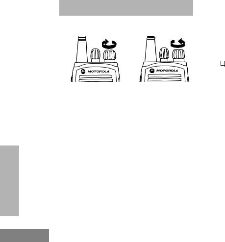
TURN THE RADIO ON OR OFF
GETTING STARTED
20
|
|
|
ON |
OFF |
|||
|
|
|
|
|
|
|
|
Rotate the ON/OFF/ |
Rotate the ON/OFF/ |
||||||
Volume knob |
Volume knob |
||||||
clockwise. If power-up |
counterclockwise until you |
||||||
is successful, you will |
hear a click and both the |
||||||
hear the Self-Test |
display and LED indicator |
||||||
Pass Tone |
turn OFF. |
||||||
( |
|
|
|
) and see |
|
||
|
|
|
|||||
the display icons light |
|
||||||
momentarily and the |
|
||||||
LED blink green. |
|
||||||
If the radio fails to |
|
||||||
power up, you will |
|
||||||
hear the Self Test Fail |
|
||||||
Tone ( |
|
|
). |
|
|||
|
|
|
|||||
|
|
|
|
|
|
|
|
The radio will need to |
|
||||||
be returned for |
|
||||||
reprogramming. |
|
||||||
|
|
|
|
|
|
|
|
English

ADJUST THE VOLUME
Turn the ON/OFF/Volume Control knob clockwise to increase the volume, or counterclockwise to decrease the volume.
–or–
Note: Your dealer can preprogram one of the programmable buttons to Volume Set.
1Hold down the Volume Set button (see page 16).
• You will hear a continuous tone.
2Turn the ON/OFF/Volume knob to the desired volume level.
3Release the Volume Set button.
SELECT AN LTR CHANNEL/ TALKGROUP
Your CP200XLS display radio can be programmed with up to 10 LTR sites and a maximum of 100 talkgroups, in total, across one or more sites (up to a total of 10 sites).
To select an LTR Channel/Talkgroup:
1Turn the Channel Selector knob to select the appropriate LTR channel/talkgroup.
–or–
Lor Mto select the appropriate LTR channel/talkgroup.
–or–
Press any of the programmable buttons to access a preprogrammed talkgroup. Then use either the Channel Selector knob or Land Mto select the appropriate LTR channel/talkgroup.
Note: The third option is available only if your radio has been programmed with a specified LTR channel/ talkgroup.
Note: Site/talkgroup settings are programmed by your dealer.
21
STARTED GETTING
English

GETTING STARTED
SELECT A CONVENTIONAL RADIO CHANNEL
Your radio offers 128 conventional channels.
To select a channel, turn the Channel Selector knob clockwise or counterclockwise until you reach the desired channel.
RECEIVE A CONVENTIONAL OR LTR CALL
1Turn your radio on.
2Adjust the radio’s volume (see page 21).
3Turn the Channel Selector knob to select the desired conventional channel or LTR talkgroup,
–or–
Lor M to select the desired
conventional channel or LTR talkgroup.
•Make sure the PTT button is released.
22
4Listen for voice activity.
•The LED indicator blinks red while your radio is receiving.
5To respond, hold the radio vertically 1 to 2 inches (2.5 to 5cm) from your mouth. Press the PTT button to talk; release it to listen.
MONITOR
It is important to monitor for traffic before transmitting to ensure that you do not “talk over” someone who is already transmitting.
1Press and hold the preprogrammed Monitor button to access channel traffic.
•If no activity is present, you will hear “white noise.”
2Once channel traffic has cleared, proceed with your call by pressing the PTT button.
English
Loading...