


 Loading...
Installation and
Operation Manual
BLE100
1GHz Broadband Line Extender
4 |
2 |
5 |
1 |
6
|
|
EMB |
|
|
A |
S |
S |
LE |
|
|
D |
|||
|
|
|||
N |
|
O |
||
I |
|
|
|
|
|
|
M EXIC |
|
|
3

Caution
These servicing instructions are for use by qualified personnel only. To reduce the risk of electrical shock, do not perform any servicing other than that contained in the Installation and Troubleshooting Instructions unless you are qualified to do so. Refer all servicing to qualified service personnel.
Special Symbols That Might Appear on the Equipment
This symbol indicates that dangerous voltage levels are present within the equipment. These voltages are not insulated and may be of sufficient strength to cause serious bodily injury when touched. The symbol may also appear on schematics.
The exclamation point, within an equilateral triangle, is intended to alert the user to the presence of important installation, servicing, and operating instructions in the documents accompanying the equipment.
For continued protection against fire, replace all fuses only with fuses having the same electrical ratings marked at the location of the fuse.
FCC Compliance
This equipment has been tested and found to comply with the limits for a Class A digital device, pursuant to Part 15 of the FCC Rules. These limits are designed to provide reasonable protection against harmful interference when the equipment is operated in a commercial environment. This equipment generates, uses, and can radiate radio frequency energy and, if not installed and used in accordance with the Installation Manual, may cause harmful interference to radio communications. Operation of this equipment in a residential area is likely to cause harmful interference in which case the user will be required to correct the interference at his/her own expense. Any changes or modifications not expressly approved by Motorola could void the user’s authority to operate this equipment under the rules and regulations of the FCC.
Canadian Compliance
This Class A digital apparatus meets all requirements of the Canadian Interference-Causing Equipment Regulations. Cet appareil numérique de la classe A respects toutes les exigences du Règlement sur le matériel brouilleur du Canada.
|
|
Declaration of Conformity |
|
|
We |
|
Motorola, Inc. |
|
|
|
|
101 Tournament Drive |
|
|
|
|
Horsham, PA 19044, U.S.A. |
|
|
declare under our sole responsibility that the |
|
|
|
|
STARLINE® |
|
Model BLE100 |
|
|
to which this declaration relates is in conformity with one or more of the following standards: |
|
|||
EMC Standards |
|
|
|
|
EN55022 |
EN55024 |
EN50083-2 |
CISPR-22 |
CISPR-24 |
Safety Standards |
|
|
|
|
EN60065 |
EN60825 |
EN60950 |
IEC 60950 + A1: 1992 + A2: 1993 + A3: 1995 + A4: 1996 |
|
following the provisions of the Directive(s) of the Council of the European Union: |
|
|
||
EMC Directive 89/336/EEC |
|
Low Voltage Directive 73/23/EEC |
|
|
|
|
|
|
|

Copyright © 2006 by Motorola, Inc.
All rights reserved. No part of this publication may be reproduced in any form or by any means or used to make any derivative work (such as translation, transformation or adaptation) without written permission from Motorola, Inc.
Motorola reserves the right to revise this publication and to make changes in content from time to time without obligation on the part of Motorola to provide notification of such revision or change. Motorola provides this guide without warranty of any kind, either implied or expressed, including, but not limited to, the implied warranties of merchantability and fitness for a particular purpose. Motorola may make improvements or changes in the product(s) described in this manual at any time.
MOTOROLA, Intelligence Everywhere and the Stylized M Logo are registered in the US Patent & Trademark Office. All other product or service names are the property of their respective owners. © Motorola, Inc. 2006

Contents
Section 1
Introduction
Using This Manual ........................................................................................................................................................................... |
1-3 |
Related Documentation................................................................................................................................................................... |
1-3 |
Document Conventions................................................................................................................................................................... |
1-3 |
If You Need Help............................................................................................................................................................................... |
1-4 |
Calling for Repairs ........................................................................................................................................................................... |
1-5 |
Section 2
Overview
Ordering Matrix ................................................................................................................................................................................ |
2-2 |
Housing............................................................................................................................................................................................. |
2-3 |
Gaskets ............................................................................................................................................................................................. |
2-4 |
Port Locations .................................................................................................................................................................................. |
2-5 |
Power Supply ................................................................................................................................................................................... |
2-6 |
Forward Path .................................................................................................................................................................................... |
2-7 |
Return Path....................................................................................................................................................................................... |
2-7 |
Ingress Control Switch.................................................................................................................................................................... |
2-8 |
Options and Accessories................................................................................................................................................................ |
2-8 |
Section 3
Amplifier Setup
Proper Handling Procedures .......................................................................................................................................................... |
3-1 |
Field Practice ........................................................................................................................................................................... |
3-1 |
Bench Setup ............................................................................................................................................................................ |
3-1 |
Forward Path Alignment.................................................................................................................................................................. |
3-2 |
Before You Begin .................................................................................................................................................................... |
3-2 |
STARLINE Cable Equalizers .................................................................................................................................................. |
3-3 |
Example 1........................................................................................................................................................................ |
3-3 |
Example 2........................................................................................................................................................................ |
3-3 |
STARLINE Cable Simulators.................................................................................................................................................. |
3-6 |
Input and Midstage Pads........................................................................................................................................................ |
3-7 |
Flatness Control ...................................................................................................................................................................... |
3-7 |
Directional Coupler Test Points............................................................................................................................................. |
3-8 |
Bode Equalization ................................................................................................................................................................... |
3-8 |
BLE100 Installation and Operation Manual
ii |
Contents |
Amplifier Level Control ........................................................................................................................................................... |
3-9 |
Manual Gain Control....................................................................................................................................................... |
3-9 |
Automatic Drive Unit/QAM Automatic Drive Unit ...................................................................................................... |
3-11 |
ADU/QADU Pads and Levels ....................................................................................................................................... |
3-12 |
Return Path Alignment................................................................................................................................................................... |
3-12 |
Before You Begin................................................................................................................................................................... |
3-12 |
Alignment Procedure ............................................................................................................................................................ |
3-13 |
Powering and Surge Protection .................................................................................................................................................... |
3-14 |
Section 4
Bench Testing
Before You Begin.............................................................................................................................................................................. |
4-1 |
Test Equipment and Connections .................................................................................................................................................. |
4-2 |
Measuring Forward Gain......................................................................................................................................................... |
4-2 |
Example: .......................................................................................................................................................................... |
4-3 |
Example: .......................................................................................................................................................................... |
4-3 |
Testing Return Gain and Response....................................................................................................................................... |
4-4 |
Example: .......................................................................................................................................................................... |
4-4 |
Completing the Test Procedures ........................................................................................................................................... |
4-4 |
Section 5
Installation
Aerial Installation.............................................................................................................................................................................. |
5-1 |
Pedestal Installation......................................................................................................................................................................... |
5-3 |
Section 6
Operating Tips
Using Amplifiers in Lower Frequency Systems ............................................................................................................................ |
6-1 |
Using Amplifiers in Lower Gain Systems ...................................................................................................................................... |
6-1 |
Appendix A
Specifications
Model BLE100S................................................................................................................................................................................ |
A-1 |
AC Current........................................................................................................................................................................................ |
A-2 |
Return Amplifier............................................................................................................................................................................... |
A-2 |
ADU Automatic Drive Unit .............................................................................................................................................................. |
A-2 |
BLE100 Installation and Operation Manual
Contents |
iii |
Appendix B
Torque Specifications
Abbreviations and Acronyms
Figures
Figure 1-1 BLE100 – closed ........................................................................................................................................................... |
1-1 |
Figure 1-2 BLE100 – open .............................................................................................................................................................. |
1-2 |
Figure 2-1 BLE100 base with electronics module ....................................................................................................................... |
2-1 |
Figure 2-2 BLE100 ordering matrix ............................................................................................................................................... |
2-2 |
Figure 2-3 BLE-HSG/15 housing and dimensions ....................................................................................................................... |
2-3 |
Figure 2-4 Housing gaskets ........................................................................................................................................................... |
2-4 |
Figure 2-5 Housing ports................................................................................................................................................................ |
2-5 |
Figure 2-6 BLE100 power supply .................................................................................................................................................. |
2-6 |
Figure 2-7 BLE100 block diagram ................................................................................................................................................. |
2-7 |
Figure 2-8 BLE100 options and accessories.............................................................................................................................. |
2-10 |
Figure 3-1 Equalizer slope versus cable....................................................................................................................................... |
3-5 |
Figure 3-2 Frequency versus cable slope .................................................................................................................................... |
3-7 |
Figure 3-3 LDR/9/1G component layout (top-left, bottom-right) ................................................................................................ |
3-8 |
Figure 3-4 ADU .............................................................................................................................................................................. |
3-11 |
Figure 3-5 QADU ........................................................................................................................................................................... |
3-11 |
Figure 4-1 Test equipment connections for bench sweeping .................................................................................................... |
4-2 |
Figure 5-1 Center-conductor pin length ....................................................................................................................................... |
5-1 |
Figure 5-2 Torque sequence .......................................................................................................................................................... |
5-2 |
Tables |
|
Table 2-1 BLE100 options and accessories ................................................................................................................................. |
2-8 |
Table 3-1 Starline Forward Equalizers – SFE-100-* ..................................................................................................................... |
3-4 |
Table 3-2 STARLINE Cable Simulators ......................................................................................................................................... |
3-6 |
Table 3-3 Gain reserve versus ambient temperature .................................................................................................................. |
3-9 |
BLE100 Installation and Operation Manual
Section 1
Introduction
The Motorola 1 GHz STARLINE® series of broadband line extenders, BLE100, accept a single input and provide 34 dB of operational gain to a single output. The BLE100 series of line extenders meets Telcordia GR-1098 core voltage surge requirements using surge waveforms as described in IEEE C62.41. The BLE100 is also FCC, CE, and CCC approved.
Features of the BLE100 include:
1003 MHz power doubling technology in enhanced gallium arsenide (E-GaAs)
Four different modular diplex filter frequency split options
Ergonomics
60/90 VAC line power option
Thermal and auto-controlled Bode equalization
−20 dB directional coupler test points
Optional return path ingress control accessories
Two-way operation capability
15-amp power passing
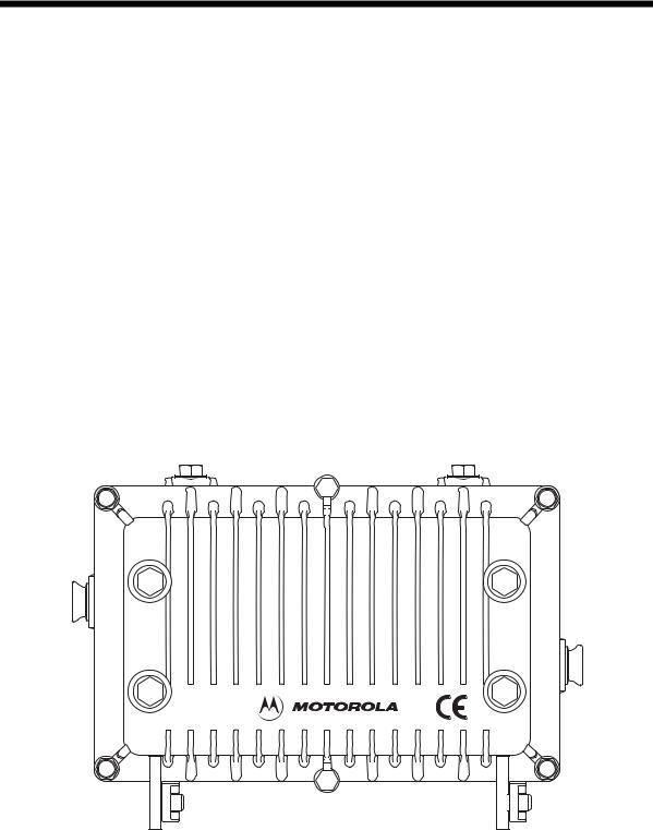
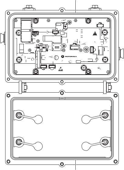
Figure 1-1 illustrates a closed BLE100 line extender.
Figure 1-1
BLE100 – closed
4 |
2 |
6 |
|
|
|
EMBL |
|
|
|
S |
S |
E |
|
A |
|
D |
||
N |
|
O |
||
I |
|
|
||
|
|
M EXIC |
|
|
5 |
1 |
3 |
|
|
BLE100 Installation and Operation Manual
1-2 |
Introduction |
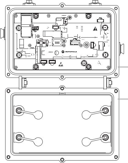
Figure 1-2 illustrates an open BLE100.
Figure 1-2
BLE100 – open
MAN
+24V DC
TEST POINT
-20dB |
ALIGN DOTS |
|
|
RCB100 |
|
|
|
ADU |
-20dB |
SFE-100-XX |
|
|
BLE |
100 |
S |
|
JXP |
|
|
|
|
|
|
|
|
||||
|
|
|
|
|
87 |
J |
|
|
|
|
|
|
JXP MID |
RC |
|
A |
|
|
|
|
|
|
|
|
K |
|
|
|
|
|
JXP IN |
|
|
|
|
|
|
|
|
IN |
|
|
|
|
N |
CHECK VOLTAGE |
|
||
|
|
|
|
|
|
||||
|
|
|
|
|
|
|
|
SELECTOR |
|
|
|
|
|
|
|
|
REFER TO MANUAL |
|
|
|
|
|
|
BODE |
|
|
|
|
H |
|
FWD |
|
|
LDR |
|
|
|
|
|
|
EQ |
|
|
|
|
|
|
L |
|
|
|
|
|
|
|
|
|
|
|
|
|
|
MAN |
|
|
|
|
|
|
|
|
|
|
AC |
ADU |
|
|
|
|
|
|
|
|
TEST |
|
|
|
||
|
|
|
|
|
|
|
|
|
|
|
|
|
|
POINT |
|
|
|
JXP |
|
|
|
|
|
|
|
|
|
|
|
|
|
|
|
FUSE |
|
|
|
IN |
|
|
|
FUSE |
AUTO |
STATUS |
|
|
|
|
|
|
SREXXX-- |
|
MONITOR |
|
|
|
|
OUT |
|
H |
RTN |
|
|
ICS |
|
|
|
|
|
L |
|
EQ |
TDU |
|
|
|
ADU |
|
|
|
|
JXP |
|
|
|
|
-20dB |
|
|
|
|
|
|
|
|
|
|
||
-20dB |
|
THERM |
JXP OUT |
|
|
|
ASSEMBLED IN MEXICO |
|
|
|
|
|
|
|
|
|
STATUS |
|
|
|
|
|
|
CAUTION: CONTAINS PARTS AND |
|
MONITOR |
|
||
|
|
|
|
ASSEMBLIES SUSCEPTIBLE TO |
|
|
|
|
|
|
|
|
|
DAMAGE BY ELECTROSTATIC |
|
|
|
|
|
|
|
|
|
DISCHARGE (ESD) |
|
|
|
REFER TO |
|
|
|
|
|
|
-16dB |
|
|
MANUAL FOR |
|
|
|
|
|
|
|
|
FUSE VALUES |
|
|
Base
Lid
BLE100 Installation and Operation Manual
Introduction |
1-3 |
Using This Manual
The following sections provide information and instructions to bench test, install, and operate the BLE100.
Section 1 |
Introduction provides a brief description of the product, identifies the information |
|
contained in this manual, and gives the help line telephone number and repair return |
|
information. |
Section 2 |
Overview describes the BLE100 and includes details on the various options and their |
|
functions. |
Section 3 |
Amplifier Setup provides instructions for full configuration and forwardand return-path |
|
alignment. |
Section 4 |
Bench Testing describes the bench test procedures that are recommended before |
|
installing the BLE100. |
Section 5 |
Installation provides instructions for installing the BLE100 and performing field alignment. |
Section 6 |
Operating Tips provides suggestions for handling field-encountered variables and |
|
addressing maintenance tasks. |
Appendix A |
Specifications lists the applicable technical specifications for the BLE100 and options. |
Appendix B |
Torque Specifications provides the appropriate torque specifications for the screws, |
|
clamps, connectors, and bolts used in the BLE100. |
Abbreviations |
The Abbreviations and Acronyms list contains the full spelling of the short forms used in |
and Acronyms |
this manual. |
This installation manual assumes that all channels are standard National Television Standards Committee (NTSC) analog channels. Refer to catalog specifications for further details pertaining to signal levels of digital channels above 550 MHz.
This installation manual uses 1003 MHz as the reference frequency unless another frequency is given. For example, quoted cable loss is understood to be at 1003 MHz.
Related Documentation
This installation manual is complete and you should not require any additional documentation to install, test, or operate the BLE100 line extender.
Document Conventions
Before you begin to use the BLE100, familiarize yourself with the stylistic conventions used in this manual:
Bold type |
Indicates text that you must type exactly as it appears or indicates a default value |
SMALL CAPS |
Denotes silk screening on the equipment, typically representing front and rear-panel |
|
controls, I/O connections and indicators (LEDs). |
* (Asterisk) |
Indicates that there are several versions of the same model number and the information |
|
applies to all models. When the information applies to a specific model, the complete model |
|
number is given. |
Italic type |
Denotes a displayed variable, a variable that you must type, or is used for emphasis |
BLE100 Installation and Operation Manual
1-4 |
Introduction |
If You Need Help
If you need assistance while working with the BLE100, contact the Motorola Technical Response Center (TRC):
Inside the U.S.: 888-944-HELP (1-888-944-4357) Outside the U.S.: 215-323-0044
Motorola Online: http://businessonline.motorola.com
The TRC is on call 24 hours a day, 7 days a week. In addition, Motorola Online offers a searchable solutions database, technical documentation, and low-priority issue creation and tracking.
Technical Response Center
Telephone Menu Options |
|
|
|
Connected Home Solutions |
|||
888-944-HELP / 215-323-0044 |
|
|
http://businessonline.motorola.com |
||||
|
|
|
|
|
|
Broadcaster, |
|
|
|
Video Products |
|
|
Satellite IRD or |
||
|
|
PRESS 1 |
|
|
|
Encoder Products |
|
|
|
|
|
|
|
|
PRESS 2 |
PRESS 1 |
PRESS 2 |
|
PRESS 3 |
|
PRESS 1 |
PRESS 2 |
|
Controllers |
Headend |
|
Set-tops |
|
Commercial |
Uplink |
|
|
|
|
|
|
|
IRD |
Encoder |
PRESS 1 |
PRESS 2 |
|
|
|
|
|
|
Digital |
Analog |
|
|
|
|
|
|
|
|
Data Networks/ |
|
|
Consumer |
||
|
Transmission Products |
|
|
Products |
|||
|
|
PRESS 3 |
|
|
|
|
PRESS 4 |
PRESS 1 |
PRESS 2 |
PRESS 3 |
|
PRESS 4 |
PRESS 5 |
PRESS 1 |
PRESS 2 |
Cable Router Cable Modems |
Transmission |
|
Network |
Multiservice |
Consumer |
Broadband |
|
Products |
VOIP |
Products |
Management |
Transport |
Satellite |
Retail |
|
|
|
|
|
|
Products |
C Band |
Support |
|
|
|
|
(MBT/MWT/MEA) |
|
|
|
Severity Level |
PRESS 1 PRESS 2 |
|
|
|
|||
1 - Critical Failure |
Network |
Network |
|
|
|
||
Licensing |
Management |
|
|
|
|||
2 - Serious Failure |
|
|
Products |
|
|
|
|
3 - Lesser Failure
4 - Technical Assistance
Issued: 04/2005
BLE100 Installation and Operation Manual
Introduction |
1-5 |
Calling for Repairs
If repair is necessary, call the Motorola Repair Facility at 1-800-227-0450 for a Return for Service Authorization (RSA) number before sending the unit. The RSA number must be prominently displayed on all equipment cartons. The Repair Facility is open from 8:00 AM to 5:00 PM Central Time, Monday through Friday.
When calling from outside the United States, use the appropriate international access code and then call 956-541-0600 to contact the Repair Facility.
When shipping equipment for repair, follow these steps:
1Pack the unit securely.
2Enclose a note describing the exact problem.
3Enclose a copy of the invoice that verifies the warranty status.
4Ship the unit PREPAID to the following address:
BCS Nogales Repair Center Attn: RSA #_________
6908 East Century Park Drive Tucson, AZ 85706
US
BLE100 Installation and Operation Manual

Section 2
Overview
The BLE100 is a two-way capable line extender used in CATV distribution systems. The BLE100 is powered by the 60/90 VAC cable supply and can be configured to pass this power to additional line extenders. Installation of the return path enables two-way signal flow.
The standard model BLE100 includes an amplifier module with an integrated DC power supply, which is normally furnished complete in the model BLE-HSG/15 housing, as shown in
Figure 2-1.
Figure 2-1
BLE100 base with electronics module
|
|
|
|
MAN |
|
|
|
|
|
|
+24V DC |
|
|
|
|
|
|
TEST POINT |
|
|
-20dB |
ALIGN DOTS |
|
|
RCB100 |
|
|
SFE-100-XX |
|
|
BLE |
100 |
S |
|
|
|
|
|
|
87 |
J |
|
|
|
JXP MID |
RC |
|
A |
|
|
|
|
|
K |
|
|
JXP IN |
|
|
|
|
|
IN |
|
|
|
|
N |
|
|
|
|
|
|
||
|
|
|
|
BODE |
|
|
|
FWD |
|
|
LDR |
|
|
|
EQ |
|
|
|
|
|
|
|
|
MAN |
|
|
|
|
|
|
|
AC |
|
ADU |
|
|
|
|
TEST |
|
|
|
|
|
|
|
|
|
|
|
|
|
POINT |
|
|
|
|
|
|
FUSE |
|
|
|
|
FUSE |
AUTO |
STATUS |
|
|
|
SREXXX-- |
|
MONITOR |
|
|
|
H |
RTN |
|
|
ICS |
|
|
L |
|
EQ |
TDU |
|
|
|
|
|
|
|
|
|
|
|
|
JXP |
|
|
|
|
-20dB |
|
THERM |
JXP OUT |
|
|
|
|
|
|
|
CAUTION: CONTAINS PARTS AND |
|
|
|
|
|
|
ASSEMBLIES SUSCEPTIBLE TO |
|
|
|
|
|
|
DAMAGE BY ELECTROSTATIC |
|
|
|
|
|
|
DISCHARGE (ESD) |
|
|
-16dB
ADU |
-20dB |
JXP |
|
CHECK VOLTAGE
SELECTOR
REFER TO MANUAL
H
L
JXP
IN
OUT
ADU
-20dB
ASSEMBLED IN MEXICO
STATUS
MONITOR
REFER TO
MANUAL FOR
FUSE VALUES
BLE100 Installation and Operation Manual

2-2 |
Overview |
Ordering Matrix
Several models of the BLE100 are available. The BLE100 is fully configured in the Motorola factory per customer request. You can find the model name on labels on the outside of the shipping carton, the side of the BLE100 housing, and the side of the electronics module.
Please see the Product Data Sheet on the Motorola on line Product Catalog for available models and associated part numbers.
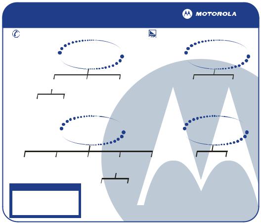
Figure 2-2 identifies and describes the model strings.
Figure 2-2
BLE100 ordering matrix
|
|
|
|
|
|
|
|
|
|
|
|
|
|
|
|
|
|
|
|
|
|
|
|
|
|
Key |
Station Slope |
|
|
|
|
|
|
|
|
|
|
|
|
|
|
|
|
|
|
|
|
|
|
|
|
|
|
||
|
|
|
|
|
|
|
|
|
|
|
|
|
|
|
|
|
|
|
|
|
|
|
|
|
|
X |
9 dB (Fmin-1003 MHz) |
|
|
|
|
|
|
|
|
|
|
|
|
|
|
|
|
|
|
|
|
|
|
|
|
||||
|
|
|
|
|
|
|
|
|
|
|
|
|
|
|
|
|
|
|
|
|
|
|
|
||||
Key |
|
|
|
|
|
Gain |
|
|
|
|
|
|
|
|
|
|
|
|
Key |
Return Gain |
|||||||
|
|
|
|
|
|
|
|
|
|
|
|
|
|
|
|
|
|||||||||||
H |
|
E-GaAs (High Output w/34 dB Gain) |
|
|
|
|
|
|
|
|
|
|
|
|
X |
High (24 dB) |
|||||||||||
|
|
BLE |
|
|
|
|
|
|
|
|
|
|
|
|
|
|
|
|
|
|
|
|
|
|
|
|
|
|
|
|
|
|
|
|
|
|
|
|
|
|
|
|
|
|
|
|
|
|
|
|
|
|
|
|
|
|
|
|
|
|
|
|
|
|
|
|
|
|
|
|
|
|
|
|
|
|
|
|
|
|
|
|
|
|
|
|
|
|
|
|
|
|
|
|
|
|
|
|
|
|
|
|
|
|
|
|
|
|
|
|
|
|
|
|
|
|
|
|
|
|
|
|
|
|
|
|
|
||||||||||||
Key |
Bandpass Split |
|
|
Key |
|
Level Control |
|
|
Key |
Housing* |
|||||||||||||||||
|
|
|
|
|
|
||||||||||||||||||||||
100S |
5-40 MHz/52-1003 MHz |
|
|
|
|
X |
None |
|
|
F |
Standard (Full Station) |
||||||||||||||||
100K |
5-42 MHz/54-1003 MHz |
|
|
|
|
A |
ADU-499.25/S |
|
|
E15 |
Electronics only (15 amp) |
||||||||||||||||
100A |
5-65 MHz/85-1003 MHz |
|
|
|
|
Q |
QADU-609.00/S |
|
|
E10 |
Electronics only (10 amp) |
||||||||||||||||
100J |
5-55 MHz/70-1003 MHz |
|
|
|
|
|
|
|
|
|
|
|
|
|
|
|
|
||||||||||
100N |
5-85 MHz/105-1003 MHz |
|
|
|
|
|
|
|
|
|
|
|
|
|
|
|
|
||||||||||
|
|
|
|
|
|
|
|
|
|
|
|
|
|
|
|
|
|
|
|
|
|
|
|
|
|
|
|
* Electronics modules available are configured for manual level control only. The ADU must be ordered and installed separately.
Notes:
1.FTECs and 20A fuses are included in all amplifiers as standard.
2.ICS and status monitor transponders will continue to be customer configurable options.
BLE100 Installation and Operation Manual
Overview |
2-3 |
Housing
The BLE100 is furnished in a BLE-HSG/15 aluminum housing that protects the electronics from weather and dissipates internally generated heat.
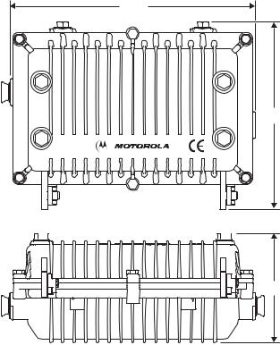
Figure 2-3 illustrates the BLE-HSG/15 housing and provides its dimensions.
Figure 2-3
BLE-HSG/15 housing and dimensions
10.6
4 |
2 |
6 |
|
|
SE |
M |
BLE |
|
|
S |
|
|||
A |
|
|
|
D |
|
N |
|
|
O |
||
I |
|
|
|
|
|
|
|
M |
EXIC |
|
|
 8.0
8.0
5 |
1 |
3 |
4.7
Coaxial cable connections to the housing are made using conventional 5/8 inch × 24 threads per-inch stinger-type connectors. Four port plugs in the cover enable access to internal test points without opening the housing.
The BLE-HSG/15 differs from the housing of the 10A BLE (model BLE-75SH and BLE-75JH) and the JLX series of line extenders. However, you can upgrade the 10A BLE and the JLX series of line extenders to the 15A BLE100 using the existing housing. To upgrade from 10A to 15A, use the BLE-15A platform assembly kit (P/N 951941-006-00). The BLE-15A kit contains 15A platform assemblies. As an alternative to the kit, you can order the BLE100 electronics module configured as a 10A unit (see Fig.2-2 BLE100 ordering matrix, Housing).
Two messenger clamps are located on the side of the housing (Figure 2-5) and are secured with 5/16 inch × 24 threads-per-inch stainless steel bolts. The bottom of the housing also contains two 5/16 × 24 threaded holes located on the vertical center-line separated by four inches center-to-center. Use these holes and the bolts from the messenger clamps for pedestal and surface-mounting installations.
BLE100 Installation and Operation Manual
2-4 |
Overview |
Gaskets
Each housing is equipped with a recessed woven-wire RF gasket and a silicone-rubber gasket to provide a seal between the housing base and lid. These gaskets provide efficient ground continuity, RF shielding, and weather protection. Both gaskets must be in place and in good condition to ensure proper operation and protection of the station. The weather gasket should be lightly coated with silicone grease each time the BLE100 is opened. Replace this gasket if it becomes damaged or deformed.
Figure 2-4
Housing gaskets
Weather gasket (silicone rubber)
|
|
|
|
MAN |
|
|
|
|
|
|
+24V DC |
|
|
|
|
|
|
TEST POINT |
|
|
-20dB |
ALIGN DOTS |
|
|
RCB100 |
|
|
SFE-100-XX |
|
|
BLE |
100 |
S |
|
|
|
|
||||
|
|
|
|
|
87 |
J |
|
|
|
JXP MID |
RC |
|
A |
|
|
|
|
|
K |
|
|
JXP IN |
|
|
|
|
|
IN |
|
|
|
|
|
N |
|
|
|
|
BODE |
|
|
|
FWD |
|
|
LDR |
|
|
|
EQ |
|
|
|
|
|
|
|
|
MAN |
|
|
|
|
|
|
|
AC |
|
ADU |
|
|
|
|
TEST |
|
|
|
|
|
|
|
|
|
|
|
|
|
POINT |
|
|
|
|
|
|
FUSE |
|
|
|
|
FUSE |
AUTO |
STATUS |
|
|
|
SREXXX-- |
|
MONITOR |
|
|
|
H |
RTN |
|
ICS |
|
||
L |
|
EQ |
TDU |
|
|
|
|
|
|
|
|
|
|
|
|
JXP |
|
|
|
|
-20dB |
|
THERM |
JXP OUT |
|
|
|
|
|
|
|
CAUTION: CONTAINS PARTS AND |
|
|
|
|
|
|
ASSEMBLIES SUSCEPTIBLE TO |
|
|
|
|
|
|
DAMAGE BY ELECTROSTATIC |
|
|
|
|
|
|
DISCHARGE (ESD) |
|
|
-16dB
ADU |
-20dB |
JXP |
|
CHECK VOLTAGE
SELECTOR
REFER TO MANUAL
H
L
JXP
IN
OUT
ADU
-20dB
ASSEMBLED IN MEXICO
STATUS
MONITOR
REFER TO
MANUAL FOR
FUSE VALUES
RF gasket (woven wire)
BLE100 Installation and Operation Manual
Loading...