


 Loading...
INSTALLATION MANUAL
DCX3200
Installation Manual

IMPORTANT SAFETY INSTRUCTIONS
•Read these instructions.
•Keep these instructions.
•Heed all warnings.
•Follow all instructions.
•Do not use this apparatus near water.
•Clean only with dry cloth.
•Do not block any ventilation openings. Install in accordance with the manufacturer’s instructions.
•Do not install near any heat sources such as radiators, heat registers, stoves, or other apparatus (including amplifiers) that produce heat.
•Do not defeat the safety purpose of the polarized or grounding-type plug. A polarized plug has two blades with one wider than the other. A grounding type plug has two blades and a third grounding prong. The wide blade or the third prong is provided for your safety. If the provided plug does not fit into your outlet, consult an electrician for replacement of the obsolete outlet.
•Protect the power cord from being walked on or pinched particularly at plugs, convenience receptacles, and the point where they exit from the apparatus.
•Only use attachments/accessories specified by the manufacturer.
•Unplug this apparatus during lightning storms or when unused for long periods of time.
•Refer all servicing to qualified service personnel. Servicing is required when the apparatus has been damaged in any way, such as the power-supply cord or plug is damaged, liquid has been spilled or objects have fallen into the apparatus, the apparatus has been exposed to rain or moisture, does not operate normally, or has been dropped.
IMPORTANT SAFETY CONSIDERATIONS
The plug is the main disconnect device. It shall remain readily accessible and operable.
The apparatus shall not be exposed to dripping or splashing and no object filled with liquids, such as vases, shall be placed on the apparatus.
DURING TRANSPORTATION TO THE SUBSCRIBER HOME
Transport the cable terminal in its shipping box or an equally padded container.
Do not expose the terminal to rain or moisture.
DURING INSTALLATION
•Do not place the cable terminal in an enclosed area where the cooling vents are blocked or impede the flow of air through the ventilation openings.
•Install the terminal so that its position does not interfere with its proper ventilation. For example, do not place the terminal on a bed, sofa, rug, or similar surface that could block the ventilation openings.
i
•Install the terminal away from heat sources such as radiators, heat registers, and stoves. Installation of the terminal near consumer electronics devices, such as stereo receiver/amplifiers and televisions, is permitted as long as the air surrounding the terminal does not exceed 40º C (104º F).
•Place the terminal on a flat surface not prone to vibration or impact.
•Do not install the terminal in an area where condensation occurs.
•To prevent the temporary loss of guide data and cause a temporarily non-responding terminal, do not plug the AC power cord into a switched power outlet.
FCC COMPLIANCE
Note: This equipment has been tested and found to comply with the limits for a Class B digital device, pursuant to part 15 of the FCC Rules. These limits are designed to provide reasonable protection against harmful interference in a residential installation. This equipment generates, uses, and can radiate radio frequency energy and, if not installed and used in accordance with the instructions, may cause harmful interference to radio communications. However, there is no guarantee that interference will not occur in a particular installation. If this equipment does cause harmful interference to radio or television reception, which can be determined by turning the equipment off and on, the user is encouraged to try to correct the interference by one or more of the following measures:
•Reorient or relocate the receiving antenna.
•Increase the separation between the equipment and receiver.
•Connect the equipment into an outlet on a circuit different from that to which the receiver is connected.
•Consult the dealer or an experienced radio/TV technician for help.
Caution: Changes or modifications not expressly approved by Motorola for compliance could void the user’s authority to operate the equipment.
This device complies with part 15 of the FCC Rules. Operation is subject to the following two conditions: (1) This device may not cause harmful interference, and (2) this device must accept any interference received, including interference that may cause undesired operation.
FCC DECLARATION OF CONFORMITY
Motorola Inc., Home and Network Mobility, 101 Tournament Drive, Horsham, PA 19044, 1-215-323-1000, declares that the DCX3200 receiver complies with 47 CFR Parts 2 and 15 of the FCC rules as a Class B digital device.
CANADA INDUSTRY CANADA (IC)
This Class B digital device complies with Canadian ICES-003.
Cet appareil numérique de la classe B est conforme à la norme NMB-003 du Canada.
ii
Caring for the Environment by Recycling
When you see this symbol on a Motorola product, do not dispose of the product with residential or commercial waste.
Recycling your Motorola Equipment
Please do not dispose of this product with your residential or commercial waste. Some countries or regions, such as the European Union, have set up systems to collect and recycle electrical and electronic waste items.
Contact your local authorities for information about practices established for your region. If collection systems are not available, call Motorola Customer Service for assistance. Please visit www.motorola.com/recycle for instructions on recycling.
© 2008 Motorola, Inc. All rights reserved. No part of this publication may be reproduced in any form or by any means or used to make any derivative work (such as translation, transformation, or adaptation) without written permission from Motorola, Inc.
MOTOROLA and the Stylized M logo are registered in the US Patent and Trademark Office. CableCARDTM, M-CardTM , and DOCSIS® are trademarks or registered trademarks of Cable Television Laboratories, Inc. HDMI is a trademark of HDMI Licensing LLC. Dolby and the double-D symbol are registered trademarks of Dolby Laboratories. Macrovison is a registered trademark of Macrovision Corporation. All other product or service names are the property of their respective owners. All rights reserved.
Motorola reserves the right to revise this publication and to make changes in content from time to time without obligation on the part of Motorola to provide notification of such revision or change. Motorola provides this guide without warranty of any kind, implied or expressed, including, but not limited to, the implied warranties of merchantability and fitness for a particular purpose. Motorola may make improvements or changes in the product(s) described in this manual at any time.
iii

CONTENTS |
|
1 Introduction .................................................................................................................................................................. |
1 |
Features .................................................................................................................................................................... |
2 |
Tuners................................................................................................................................................................. |
2 |
Standard Audio/Video Features..................................................................................................................... |
2 |
Standard Data Features .................................................................................................................................. |
2 |
Standard Miscellaneous Features ................................................................................................................ |
3 |
If You Need Help ...................................................................................................................................................... |
3 |
Calling for Repairs ................................................................................................................................................... |
3 |
2 Overview ....................................................................................................................................................................... |
5 |
Front Panel................................................................................................................................................................ |
5 |
Rear Panel ................................................................................................................................................................ |
5 |
M-Card™................................................................................................................................................................... |
6 |
3 Installation .................................................................................................................................................................... |
7 |
Before You Begin..................................................................................................................................................... |
7 |
Cold Reset Procedure...................................................................................................................................... |
7 |
Cold Reset Method ................................................................................................................................... |
7 |
Video Connection Options .............................................................................................................................. |
8 |
Audio Connection Options .............................................................................................................................. |
9 |
Installation Overview .............................................................................................................................................. |
9 |
Connecting HDTV — Single Connection for Video/Audio............................................................................... |
10 |
Cable-In ........................................................................................................................................................... |
10 |
HDMI ................................................................................................................................................................ |
10 |
IEEE-1394 ......................................................................................................................................................... |
10 |
Connecting HDTV — Separate Video/Audio Connections ............................................................................. |
12 |
Cable In............................................................................................................................................................ |
12 |
DVI .................................................................................................................................................................... |
12 |
Component Video (YPbPr)............................................................................................................................. |
12 |
Audio ................................................................................................................................................................ |
12 |
Connecting an A/V Receiver — Audio............................................................................................................... |
14 |
Connecting a Standard-Definition TV (SDTV) ................................................................................................... |
16 |
Connecting a Standard-Definition TV (SDTV) and VCR/DVD Recorder ........................................................ |
17 |
Connecting an A/V Receiver, TV, and VCR......................................................................................................... |
19 |
Data Device Connections..................................................................................................................................... |
21 |
Operational Check for the Remote Control........................................................................................................ |
22 |
Configuring the Audio, Video, and Closed Caption Settings........................................................................... |
22 |
Graphics Overlaying the Video............................................................................................................................ |
31 |
4 Diagnostics ................................................................................................................................................................. |
33 |
v |
|
1 INTRODUCTION |
|
Using the Diagnostics........................................................................................................................................... |
33 |
General Status ....................................................................................................................................................... |
34 |
Purchase Status .................................................................................................................................................... |
36 |
Out-Of-Band (OOB) Status ................................................................................................................................... |
37 |
Agile OOB Tuner Hunting...................................................................................................................................... |
38 |
Manual Selection of the OOB Frequency (OSD Frequency Override in Hunted Mode)...................... |
38 |
In-Band Status ....................................................................................................................................................... |
39 |
Unit Address........................................................................................................................................................... |
41 |
Separable Security................................................................................................................................................ |
42 |
Current Channel Status ........................................................................................................................................ |
43 |
RF Modem (Upstream).......................................................................................................................................... |
46 |
Code Modules ........................................................................................................................................................ |
46 |
Memory Configuration.......................................................................................................................................... |
48 |
Audio/Video Status................................................................................................................................................ |
48 |
Interface Status ..................................................................................................................................................... |
52 |
User Setting Status ............................................................................................................................................... |
55 |
DOCSIS Status ....................................................................................................................................................... |
57 |
Application Specific Information ........................................................................................................................ |
61 |
Interactive Status .................................................................................................................................................. |
61 |
5 Troubleshooting.......................................................................................................................................................... |
65 |
FIGURES |
|
Figure 1-1 Front and Rear views................................................................................................................................... |
1 |
Figure 2-1 Front panel..................................................................................................................................................... |
5 |
Figure 2-2 Rear panel ..................................................................................................................................................... |
6 |
Figure 3-1 Connecting the DCX Set-top to an HDTV — Single Connection for Video/Audio............................ |
11 |
Figure 3-2 Connecting the DCX Set-top to an HDTV — Separate Video/Audio.................................................. |
13 |
Figure 3-3 Connecting the DCX Set-top to an A/V Receiver — Audio.................................................................. |
15 |
Figure 3-4 Connecting a Standard-Definition TV (SDTV)........................................................................................ |
16 |
Figure 3-5 Connecting the DCX Set-top to an A/V Receiver, Standard-Definition TV (SDTV), and VCR/DVD |
|
Recorder......................................................................................................................................................................... |
18 |
Figure 3-6 Connecting the DCX Set-top to an A/V Receiver, Standard-Definition TV (SDTV), and VCR/DVD |
|
Recorder......................................................................................................................................................................... |
20 |
Figure 3-7 Sample data devices you can connect to the DCX3200....................................................................... |
21 |
TABLES |
|
Table 2-1 Front panel ...................................................................................................................................................... |
5 |
Table 2-2 Rear panel connections................................................................................................................................ |
6 |
Table 3-1 Operational check procedures.................................................................................................................. |
22 |
vi |
|

1 INTRODUCTION
This manual provides instructions for cable operator personnel to install the Motorola DCX3200 All-Digital High-Definition Cable Set-top. This unit includes a high-end processor, expanded memory, and enhanced graphics to support digital and on-demand broadcast and interactive services. It provides a full complement of interconnection options.
The DCX3200 provides advanced capabilities, including:
•Authorization and purchase of on-demand programming
•HDTV output through component video (YPbPr), High-Definition Multimedia Interface (HDMI™), or IEEE-1394
•Surround-sound audio through a variety of analog and digital interconnection options
•DOCSIS 2.0+ embedded Cable Modem with support for DSG
•Ethernet and Universal Serial Bus (USB) 2.0 ports for future home networking applications
•Adaptability to various software platforms
As with all Motorola digital cable set-tops, the hardware features are enabled by core operating and third party application software.
Figure 1-1 Front and Rear views
1
1 INTRODUCTION
Features
Tuners
•One All Digital 1 GHz (54 to 1002 MHz) video tuner
o MPEG-2 Main Profile @ High Level (High-Definition) o MPEG-4 H.264 (AVC) High-Definition decode
•One dedicated tuner for the DOCSIS high-speed data services channel, up to 1 GHz
•One dedicated tuner for the out-of-band (OOB) control channel
Standard Audio/Video Features
•ITU standard 64/256 QAM/FEC/enhanced adaptive equalizer
•DES based encryption/DCII (via inserted CableCARD™) access control
•Out-of-band data receiver (70-130 MHz) 2.048 Mbps
•Digital video scaling (picture in graphics)
•Accelerated 2-D graphics support in hardware
•Macrovision® copy protection
•High-Definition video output through:
o HDMI™ (also compatible with DVI using an HDMI-to-DVI converter cable)
o Component Video (YPbPr)
oIEEE-1394
•Standard-Definition video output through:
oS-Video
o Baseband
oRF
•Audio output through:
oS/PDIF electrical and optical digital audio connections
o One Baseband L/R stereo analog audio connection
Standard Data Features
•Integrated DOCSIS 2.0+ capable cable modem
•64 MB FLASH memory
•256 MB DRAM
•Two Universal Serial Bus (USB) 2.0 ports (one on the front panel and one on the rear panel)
•10/100 Mbps Ethernet Port (RJ-45) on the rear panel
2
1 INTRODUCTION
•On-board real-time RF return (DOCSIS compliant)
Standard Miscellaneous Features
•Messaging capabilities
•Digital diagnostics
If You Need Help
If you need assistance while working with the DCX3200, contact the Motorola Technical Response Center (TRC):
•Inside the U.S.: 1-888-944-HELP (1-888-944-4357)
•Outside the U.S.: 1-847-725-4011
•Motorola Online: http://businessonline.motorola.com/
The TRC is on call 24 hours a day, 7 days a week. In addition, Motorola Online offers a searchable solutions database, technical documentation, and low-priority issue creation and tracking. For specific toll-free numbers when calling from outside the United States, please refer to the product manual or our Web page.
Calling for Repairs
If a Motorola set-top requires repair service, please call one of the following Motorola Authorized Service Centers:
Company |
From USA or Canada |
Outside USA or Canada |
World Wide Digital |
1-800-227-0450 |
1-956-541-0600 |
Teleplan |
1-800-352-5274 |
1-302-322-6088 |
To ensure efficient service, request a Return for Service Authorization (RSA) number. Be sure to display the RSA number prominently on all equipment boxes.
The Service Center will provide the shipping address of the location performing your repairs.
To ship your equipment for repair:
•Pack the unit securely, if possible in its original factory shipping carton.
•Print or display the RSA number so it is easily visible on all equipment boxes.
•Enclose a note describing the exact problem. Complete and enclose the checklist provided with the unit.
•Ship the unit PREPAID to the address provided by the Service Center.
3
2 OVERVIEW
Front Panel
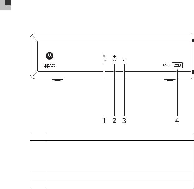
Figure 2-1 Front panel
Table 2-1 Front panel
1Power — turns the set-top on and off (standby)
2Data — Dual function LED
•Flashes twice per second to indicate unit is booting
•Flashes once per second to indicate unit is provisioning
•Illuminates to indicate one or more set-top boxes and or DVR devices are detected on the home network
3Rec — Unit is in record mode on a home network device (only available on DCX3200-M model) with MoCA option
4USB connector*
*The availability of certain features is dependent upon application support.
Rear Panel
The rear panel contains connectors for video, audio, and RF cabling; data output; and modem and data interface connectors. Some connectors are not enabled and require the support of application software.
5
2 OVERVIEW
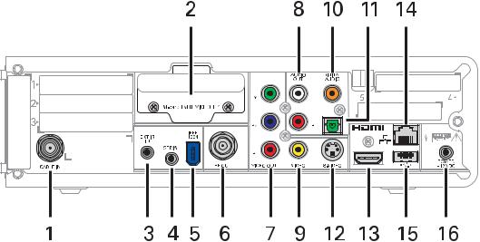
Figure 2-2 Rear panel
Table 2-2 Rear panel connections
1 |
Cable In — Connects to cable signal from the service provider |
|
|
2 |
M-Card — Inserted M-Card |
|
|
3 |
Ext IR Input – Connects to a remote control receiver accessory cable |
|
|
4 |
Serial — Data test connector (service personnel only) |
|
|
5 |
IEEE-1394 — Audio and video device connection |
|
|
6 |
RF Out — Ch 3/4 modulated audio/video (SDTV) to TV or VCR |
|
|
7 |
Video outputs / YPbPr — Component video output (HDTV) |
|
|
8 |
Audio Out — L/R audio (SDTV) |
|
|
9 |
Video Out — Composite Video (SDTV) |
|
|
10 |
Digital Audio (coaxial) — Provides Dolby® Digital 5.1 audio or PCM output |
11 |
Digital Audio (optical) — Provides Dolby® Digital 5.1 audio or PCM output |
12 |
S-Video — Connects to S-Video (SDTV) input of TV or VCR |
|
|
13 |
HDMI™ — High-Definition TV (HDTV) connector (Provides Dolby® Digital Plus (7.1) audio) |
|
|
14 |
Ethernet* — Network connection |
|
|
15 |
USB* 2.0 — High-Speed peripheral device connection |
|
|
16 |
Power connector |
|
|
* Availability of certain features is dependent upon application support.
M-Card™
The M-Card is required to view cable television programs or interactive on-demand programs. The M-Card should not be removed from the DCX3200.
6

3 INSTALLATION
Before You Begin
Before you move or change components on the subscriber’s entertainment system:
•Review the installation instructions.
•Determine if you are connecting to a standard analog NTSC TV (supporting an RF input), a composite (baseband) video input, or a High-Definition TV (supporting component video input, HDMI™ input, or an IEEE-1394 input).
•Determine if the subscriber has other equipment to be connected to the terminal (home theater or A/V receiver, VCR, etc.).
•Verify that you have the necessary cables and other required items.
Cold Reset Procedure
This section describes the Cold Reset procedure for Motorola’s DCX3200 set-top. The cold reset is generally used by operational and field personnel to accomplish the following:
•Restore the set-top to a known state.
•Clear channel maps and application settings.
•Remove application and software objects above the platform code.
•Clear the Out of Band (OOB) Last Known Carrier (LKC) and force the units to hunt for a new OOB control channel.
Cold Reset Method
1.Remove the set-top from its packaging.
2.Plug in a serial connector to the DCX3200 and open a terminal window.
3.AC power cycle the set-top.
4.When the words “Waiting for IR…” appear in the terminal window, press the Volume Down (–) button on the remote control.
5.All the following lights on the front panel LEDS will light up: Power, Data, and Record (Record is only present on MoCA models).
6.Press the following sequence of numbers on the remote control: 3, 2, and 8.
7.As each number in the sequence is pressed, the front panel LEDs will extinguish in the following order: Power, Data, and then Record (Record is only present on MoCA models.) In addition, the terminal window will echo back each button press as D, C, and X for each number in the sequence.
8.The set-top will cold reset.
7
3 INSTALLATION
Video Connection Options
Use the following guidelines to determine the best video connection for the subscriber’s home entertainment system. To determine the available video inputs on the TV, check the manual supplied with the TV or the TV itself.
The DCX3200 offers the following video outputs:
Component |
HDTV and |
The YPbPr output provides three component analog video signals |
(YPbPr) |
SDTV |
to the TV. It is the most widely supported HD video connection. |
|
|
|
HDMI™ |
HDTV and |
HDMI™ and IEEE-1394 provide higher-quality digital HD video |
or |
SDTV |
signals than analog component video signals. If the TV has an |
IEEE-1394 |
|
HDMI™ or a DVI input, use the HDMI™ output instead of the |
|
|
IEEE-1394 output. |
|
|
HDMI™ and IEEE-1394 are video and audio connections. If you |
|
|
use HDMI™ or IEEE-1394, no separate audio connection to the TV |
|
|
is required. |
|
|
HDMI™ is compatible with DVI. If the TV has a DVI input, you can |
|
|
use an HDMI-to-DVI converter cable or adapter to connect the DVI- |
|
|
equipped TV to the HDMI-equipped DCX3200. |
|
|
If you use the IEEE-1394 connection, you will be unable to see on- |
|
|
screen graphics (such as the EPG). |
|
|
|
S-Video |
SDTV only |
If the TV has an S-Video input, use S-Video. S-Video is the highest- |
|
|
quality Standard-Definition video output on the DCX3200. |
|
|
|
Video |
SDTV only |
If the TV does not have an S-Video input, use the composite video |
(composite) |
|
(video) output. |
|
|
|
RF |
SDTV only |
If the TV only has a coaxial RF input, connect it to the DCX3200 |
|
|
RF out connector. |
|
|
|
8
3 INSTALLATION
Audio Connection Options
When connecting to a home theater receiver, depending on its inputs, you can use the following DCX3200 audio outputs:
HDMI |
Unlike a DVI connection, an HDMI™ connection is capable of carrying |
|
digital video and audio signals to the TV or a home theater receiver |
|
equipped with HDMI™ switching support. |
|
The HDMI™ connection can deliver Dolby® Digital Plus, Dolby® Digital, |
|
Linear PCM, and other digital audio formats to a compatible TV or home |
|
theater receiver. |
|
|
Digital audio |
If the TV or home theater receiver supports it, use either the S/PDIF |
optical (S/PDIF) or |
digital audio optical or S/PDIF digital audio coaxial outputs to deliver |
digital audio |
Dolby® Digital and Linear PCM audio to a Dolby® Digital home theater |
coaxial (S/PDIF) |
receiver. |
|
• For an HDMI™ or IEEE-1394 video connection, no additional audio |
|
connections to the TV are required. |
|
• For RF output, no further audio connection is required. |
|
|
Baseband Audio |
If the audio receiver does not support Dolby® Digital, use the baseband |
L / R |
AUDIO L and R outputs to connect to the audio receiver. |
|
|
Connect the stereo audio cable to the AUDIO L and R connectors on the DCX3200 and the audio left and right connectors on the TV. If the equipment supports it, use either the optical S/PDIF or coaxial digital S/PDIF output (there is no difference in audio quality between the two) instead of the AUDIO L and R outputs. These outputs offer better audio quality, including support for Dolby® Digital 5.1 Surround Sound.
The cabling diagrams show audio/video (A/V) connections to an audio receiver, where the receiver functions as an A/V router. When connecting to an audio receiver, reference its installation guide for directions on connecting to baseband and digital audio ports.
The VCR and TV receive their A/V signals from the currently selected input device on the audio receiver. This is important when the subscriber has another A/V device such as a DVD player, a secondary VCR, a CD player, or other electronic component. Motorola recommends connecting the TV to the monitor output so on-screen menus for the receiver can be displayed. (Receivers themselves often have interactive on-screen menus.)
Installation Overview
1. Determine if you are connecting to a:
High-Definition |
Use the component video (YPbPr), HDMI, or IEEE-1394 outputs. No other |
TV or monitor |
video connection supports HDTV. |
|
If the TV has a DVI input, connect a DVI-to-HDMI adapter or cable to the |
|
HDMI™ out connector on the DCX set-top instead of the IEEE-1394 |
|
connection and the DVI-HDTV connector on the TV. |
|
|
Standard- |
Connect the S-Video connector using an S-video cable or connect the |
Definition TV |
composite video connector using a composite (RCA phono) cable. If the |
|
TV only has a coaxial RF input, connect it to the DCX3200 RF OUT |
|
connector. |
|
|
|
9 |
3INSTALLATION
2.Determine if you are connecting the audio to a home theater receiver or directly to the TV:
•For an HDMI™ or IEEE-1394 video connection, no additional audio connections to the TV are required.
•If the receiver or TV has a digital audio (S/PDIF) input, use the digital audio
OPTICAL (S/PDIF) or COAXIAL (S/PDIF) outputs.
•Otherwise, use the baseband left and right audio outputs.
3.Locate the cabling diagram(s) that best match the subscriber’s configuration.
4.Connect the audio and video cables in a manner matching that diagram.
5.Determine if you are connecting to a data device (see Data Device Connections in this section). For installation details, refer to the instructions included with the data device.
6.Connect the cable terminal to the coaxial cable wall outlet.
7.Perform the operational check for the remote control.
8.Optimize the High-Definition settings.
Connecting HDTV — Single Connection for Video/Audio
Cable-In
Connect an RF coaxial cable to the cable wall outlet and the CABLE IN connector on the DCX set-top.
HDMI
If the TV has an HDMI™ input, this is for both audio and video if you are using the TV speakers. Connect a Standard HDMI™ cable to the TV and to the HDMI™ connect on the DCX set-top.
IEEE-1394
If the HDTV has an IEEE-1394 connector, you can use the IEEE-1394 for both the video and audio connection:
•Connect an IEEE-1394 cable to the IEEE-1394 connector on the HDTV and DCX settop.
Note: On screen graphics will not be displayed when you are using the IEEE-1394 connection on the rear panel of the DCX set-top.
If there is an audio/video receiver and you are not using the TV’s speakers, go to Connecting the DCX Set-top to an A/V Receiver — Audio.
10

3 INSTALLATION
Figure 3-1 Connecting the DCX Set-top to an HDTV — Single Connection for Video/Audio
Choose
one
HDMI |
IEEE 1394 |
DCX3200
|
|
|
AUDIO |
|
DIGITAL |
|
|
|
|
OUT |
|
AUDIO |
|
|
|
Y |
|
L |
5 |
4 |
|
M-card TM DEVICE ONLY |
|
|
|
|
|
|
|
Pb |
|
R |
|
|
EXT IR |
IEEE |
|
|
|
|
|
1394 |
|
|
|
|
|
|
IN |
|
|
|
|
|
|
|
SERIAL |
|
|
|
|
|
|
|
Pr |
|
|
|
|
|
RF OUT |
VIDEO OUT |
VIDEO |
|
S-VIDEO |
POWER |
CABLE IN |
|
+12 VDC |
Cable in 
Because HDMI and IEEE-1394 provide both video and audio output, no additional audio connections to the TV are required if you use either of these connections.
Alternate
HDTV |
|
|
CABLE/ |
IEEE 1394 |
HDMI |
ANTENNA IN |
|
|
|
|
|
|
|
Alternate |
|
|
|
A/V Receiver |
|
|
|
|
|
|
|
|
AUDIO |
R |
VIDEO |
COMPONENT VIDEO |
DIGITAL AUDIO |
5.1 CH INPUT |
|||
L |
VIDEO S-VIDEO |
|
|
COAX IN |
|
|
CENTER |
|
|
|
|
|
|
|
|
||
DVD |
|
|
|
|
|
|
L |
|
CABLE/TV |
|
|
IN |
OUT |
OPTICAL IN |
|
R |
|
|
|
|
|
|
|
|||
|
|
|
|
|
|
FRONT |
SURROUND |
SUB- |
|
|
|
|
Y |
|
|
|
WOOFER |
|
|
|
|
|
|
|
|
|
VIDEO 2 |
|
|
|
|
|
|
|
|
|
|
|
|
Pb |
TV/MONITOR |
|
HDMI |
|
|
|
|
|
OUTPUT |
|
|
|
|
IN |
|
|
|
|
|
IN |
|
|
VCR |
|
|
|
Pr |
VIDEO S-VIDEO |
|
|
|
OUT |
|
|
|
|
|
|
|
|
|
|
|
|
|
OUT |
|
|
|
|
|
|
|
|
|
|
|
|
|
Alternate |
|
|
|
|
|
|
|
Note: Only (1) HDTV video/audio connection needs to be made to an HDTV.
Note: On-screen graphics will not be displayed when using IEEE-1394 connection. Refer to Graphics Overlaying the Video for more information.
Note: Solid lines indicate optimum connections.
Note: Optional HDMI™ connection to A/V Receiver shown but not required.
11
3 INSTALLATION
Connecting HDTV — Separate Video/Audio Connections
Cable In
Connect an RF coaxial cable to the cable wall outlet and the Cable In connector on the DCX set-top.
DVI
If the TV has a DVI input, use the DVI connection for the video:
•Connect a HDMI-to-DVI adapter or cable to the HDMI™ out connector on the DCX set-top and the DVI connector on the TV.
Note: A DVI connection supports only the video connection between the DCX set-top and the HDTV. To connect your audio connections with your TV speakers, go to Audio section below. To connect the audio connections for an A/V receiver, go to Connecting the DCX Set-top to an A/V Receiver — Audio.
Component Video (YPbPr)
Connect the component video cables to the Y, Pb, and Pr connectors on the HDTV and the DCX set-top.
Note: This connection supports only the high-definition video connection between the DCX set-top and the HDTV. To connect your audio connections with your TV speakers, go to Audio section below. To connect the audio connections for the HDTV, go to Connecting the DCX Set-top to an A/V Receiver — Audio.
Audio
If the TV does not have digital audio inputs:
•Connect the stereo audio cable to the AUDIO L and R connectors on the DCX3200 Series set-top and the audio left and audio right connectors on the HDTV.
If the TV supports a digital audio input:
•If the equipment supports it, use the digital audio OPTICAL S/PDIF or COAXIAL S/PDIF outputs instead of the AUDIO L and R outputs. S/PDIF offers better audio quality, including support for Dolby® Digital audio.
For more information on configuring the DCX setup-top settings, see Configuring Audio, Video, and Closed Caption Settings.
12
3 INSTALLATION
Figure 3-2 Connecting the DCX Set-top to an HDTV — Separate Video/Audio
Choose
one
L/R audio |
HDMI |
Component |
|
|
video |
DCX3200
AUDIO |
DIGITAL |
OUT |
AUDIO |
|
|
Y |
L |
5 |
4 |
|
M-card TM DEVICE ONLY |
|
|
|
|
|
|
Pb |
R |
|
|
EXT IR |
IEEE |
|
|
|
|
1394 |
|
|
|
|
|
IN |
|
|
|
|
|
|
SERIAL |
|
|
|
|
|
|
Pr |
|
|
|
|
RF OUT |
VIDEO OUT |
VIDEO |
S-VIDEO |
POWER |
CABLE IN |
+12 VDC |
Cable in
Alternate 
|
HDTV |
Component |
Component |
Video Input |
Audio Input |
Y |
AUDIO LEFT |
CABLE/ DVI-D ANTENNA IN
Pb |
AUDIO RIGHT |
 Pr
Pr
HDMI-to-DVI
adapter
Note: If the receiver can check the baseband and digital audio (S/PDIF) ports for appropriate channels, connect both the baseband and digital audio connections. Otherwise, do not connect both the baseband left/right composite connections and the coaxial digital connection. The baseband connections are not necessary because the digital audio port provides a single audio interface for digital channels.
Note: If the A/V receiver includes HDMI™ inputs & output(s) then the DCX3200 HDMI™ output can be directly connected to the A/V receiver.
13
3 INSTALLATION
Connecting an A/V Receiver — Audio
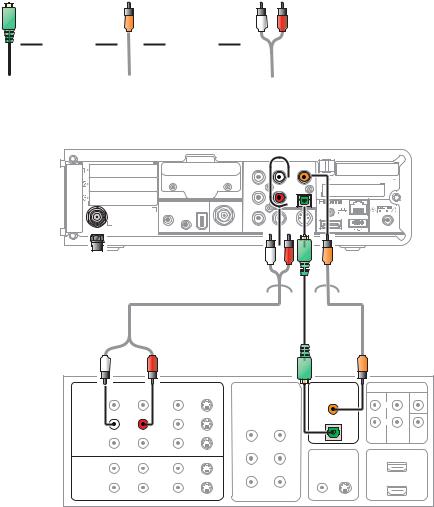
There are several options available for audio connections to the A/V receiver:
•Digital audio (OPTICAL S/PDIF)
•Digital audio (COAXIAL S/PDIF)
•Stereo audio (AUDIO L and R)
If the A/V receiver supports it, the optical (S/PDIF) or coaxial (S/PDIF) audio outputs may be used in place of the stereo audio outputs (AUDIO L and R). These outputs offer a higher level of audio quality, including support for Dolby® Digital audio.
•Digital audio optical (S/PDIF) — Connect the optical cable to the digital audio optical connector on the DCX set-top and the optical connector on the A/V receiver.
•Digital audio coaxial (S/PDIF) — Connect the digital audio cable to the digital audio connector on the DCX set-top and the DIGITAL INPUT COAX connector on the A/V receiver.
•Stereo audio — Connect the stereo audio cable to the AUDIO L and R connectors on the DCX set-top and the AUDIO LEFT and AUDIO RIGHT connectors on the A/V receiver.
For information on configuring the DCX set-top settings, see Configuring the Audio, Video, and Closed Caption Settings.
14
3 INSTALLATION
Figure 3-3 Connecting the DCX Set-top to an A/V Receiver — Audio
Choose |
Choose |
|
|
one |
|
one |
|
Digital audio |
Digital audio |
L/R audio |
|
optical |
|
coaxial |
|
DCX3200
|
|
|
AUDIO |
|
DIGITAL |
|
|
|
|
OUT |
|
AUDIO |
|
|
|
Y |
|
L |
5 |
4 |
|
M-card TM DEVICE ONLY |
|
|
|
|
|
|
|
Pb |
|
R |
|
|
EXT IR |
IEEE |
|
|
|
|
|
1394 |
|
|
|
|
|
|
IN |
|
|
|
|
|
|
|
SERIAL |
|
|
|
|
|
|
|
Pr |
|
|
|
|
|
RF OUT |
VIDEO OUT |
VIDEO |
|
S-VIDEO |
POWER |
CABLE IN |
|
+12 VDC |
Cable in 
Alternate Alternate
|
|
|
|
|
|
|
A/V |
|
|
|
|
|
|
|
|
|
Receiver |
||
|
AUDIO |
VIDEO |
COMPONENT VIDEO |
DIGITAL AUDIO |
5.1 CH INPUT |
||||
L |
R |
VIDEO |
S-VIDEO |
|
|
COAX IN |
|
|
CENTER |
|
|
|
|
|
|
|
|
||
DVD |
|
|
|
|
|
|
|
L |
|
CABLE/TV |
|
|
|
IN |
OUT |
OPTICAL IN |
|
R |
|
|
|
|
|
|
|
||||
|
|
|
|
|
|
|
|||
|
|
|
|
|
|
|
FRONT |
SURROUND |
SUB- |
|
|
|
|
|
Y |
|
|
|
WOOFER |
|
|
|
|
|
|
|
|
|
|
VIDEO 2 |
|
|
|
|
|
|
|
|
|
|
|
|
|
|
Pb |
TV/MONITOR |
|
HDMI |
|
|
|
|
|
|
OUTPUT |
|
|
|
|
|
|
|
|
|
|
IN |
|
|
|
IN |
|
|
|
|
|
|
|
|
|
VCR |
|
|
|
|
Pr |
VIDEO S-VIDEO |
|
|
|
OUT |
|
|
|
|
|
|
|
|
|
|
|
|
|
|
|
OUT |
|
|
|
|
|
|
|
|
|
|
|
|
|
Note: Because some entertainment equipment cannot simultaneously support baseband composite video and S-Video, never simultaneously connect both video inputs.
Note: This connection method does not support HDTV. For information, see Connecting HDTV — Separate Video/Audio Connections in this section.
15
3 INSTALLATION
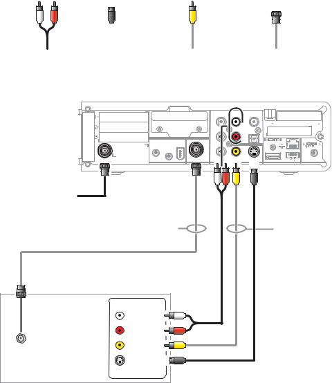
Connecting a Standard-Definition TV (SDTV)
1.Connect the stereo audio cable to the AUDIO L and R connectors on the DCX settop and the AUDIO L and AUDIO R connectors on the Stereo TV (SDTV).
2.Connect a video cable to the VIDEO OUT connector on the DCX set-top and the INPUT VIDEO on the TV or an S-video cable to the S-VIDEO connectors on the DCX set-top and the TV.
Note: These video connection methods do not support HD video. If you have an HDTV, see Connecting HDTV — Separate Video/Audio Connections.
Figure 3-4 Connecting a Standard-Definition TV (SDTV)
|
|
|
|
Choose |
|
|
|
Choose |
|||
|
|
||||||||||
|
|
|
|
one |
|
|
|
|
one |
|
|
|
|
|
|
|
Video |
RF audio/video |
|||||
L/R audio |
S-Video |
||||||||||
|
|
|
|
(composite) |
|
(coax) |
|||||
DCX3200
|
|
|
AUDIO |
|
DIGITAL |
|
|
|
|
OUT |
|
AUDIO |
|
|
|
Y |
|
L |
5 |
4 |
|
M-card TM DEVICE ONLY |
|
|
|
|
|
|
|
Pb |
|
R |
|
|
EXT IR |
IEEE |
|
|
|
|
|
1394 |
|
|
|
|
|
|
IN |
|
|
|
|
|
|
|
SERIAL |
|
|
|
|
|
|
|
Pr |
|
|
|
|
|
RF OUT |
VIDEO OUT |
VIDEO |
|
S-VIDEO |
POWER |
CABLE IN |
|
+12 VDC |
Cable in |
|
Alternate |
Alternate |
Standard-Definition TV |
|
INPUT |
|
AUDIO LEFT |
|
AUDIO RIGHT |
|
VIDEO |
|
CABLE/ |
|
ANTENNA IN |
|
S-VIDEO |
|
16
Loading...