


q Read this manual carefully before operating this vehicle.
OWNER’S MANUAL
MT09
MT09A
B87-28199-E00

EAU70070
Q Read this manual carefully before operating this vehicle. This manual should stay with this vehicle if it is sold.
YAMAHA MOTOR ELECTRONICS CO., LTD.
1450-6, Mori, Mori-machi, Shuchi-gun, Shizuoka-ken, 437-0292 Japan
DECLARATION of CONFORMITY
For
|
|
Product: IMMOBILIZER |
|
|
Model: 1RC-00 |
Supplied by |
|
Technical Construction File held by |
YAMAHA MOTOR ELECTRONICS |
YAMAHA MOTOR ELECTRONICS |
|
CO.,LTD. |
|
CO.,LTD. |
1450-6 Mori, Mori-machi Shuchi-gun |
1450-6 Mori, Mori-machi Shuchi-gun |
|
Shizuoka 437-0292 Japan |
|
Shizuoka 437-0292 Japan |
|
Standard used for comply |
|
R&TTE Directive |
EN 60950-1: 2006 + Amd.11:2009 + Amd.1:2010 + |
|
(Article 3.1(a) Safety) |
Amd.12: 2011 |
|
|
EN 62479: 2010 |
|
R&TTE Directive |
97/24/EC from 17.06.1997 |
|
(Article 3.1(b) EMC) |
|
|
R&TTE Directive |
EN 300 330-1 V1.7.1: 2010 |
|
(Article 3.2 Spectrum) |
EN 300 330-2 V1.5.1: 2010 |
|
Means of Conformity
We declare under our sole responsibility that the Product (s) is conformity with the essential requirements and other relevant requirements of the
Radio and Telecommunication Terminal Equipment (R&TTE) Directive (1999/5/EC).
Date of issue: |
January 12, 2015 |
Signature of Responsible Person:
Kazuhide Takasugi
GENERAL MANAGER
QUALITY ASSURANCE DIV.
Introduction
EAU10103
Welcome to the Yamaha world of motorcycling!
As the owner of the MT09/MT09A, you are benefiting from Yamaha’s vast experience and newest technology regarding the design and manufacture of high-quality products, which have earned Yamaha a reputation for dependability.
Please take the time to read this manual thoroughly, so as to enjoy all advantages of your MT09/MT09A. The Owner’s Manual does not only instruct you in how to operate, inspect and maintain your motorcycle, but also in how to safeguard yourself and others from trouble and injury.
In addition, the many tips given in this manual will help keep your motorcycle in the best possible condition. If you have any further questions, do not hesitate to contact your Yamaha dealer.
The Yamaha team wishes you many safe and pleasant rides. So, remember to put safety first!
Yamaha continually seeks advancements in product design and quality. Therefore, while this manual contains the most current product information available at the time of printing, there may be minor discrepancies between your motorcycle and this manual. If there is any question concerning this manual, please consult a Yamaha dealer.
EWA10032
 WARNING
Please read this manual carefully and completely before operating this motorcycle.
Important manual information
EAU10134
Particularly important information is distinguished in this manual by the following notations:
|
|
|
|
This is the safety alert symbol. It is used to alert you to potential personal injury |
|
|
|
|
hazards. Obey all safety messages that follow this symbol to avoid possible injury |
|
|
|
|
or death. |
|
|
|
|
|
|
|
|
|
|
|
|
|
|
A WARNING indicates a hazardous situation which, if not avoided, could result in |
|
WARNING |
|
||
|
|
death or serious injury. |
||
|
|
|
|
|
|
|
|
|
|
|
|
|
|
|
|
|
|
|
A NOTICE indicates special precautions that must be taken to avoid damage to the |
|
NOTICE |
|
|
|
|
|
vehicle or other property. |
||
|
|
|
|
|
|
|
|
|
|
TIP |
A TIP provides key information to make procedures easier or clearer. |
|
|
*Product and specifications are subject to change without notice.
Important manual information
EAU10201
MT09/MT09A
OWNER’S MANUAL ©2015 by Yamaha Motor Co., Ltd.
1st edition, October 2015 All rights reserved.
Any reprinting or unauthorized use without the written permission of Yamaha Motor Co., Ltd.
is expressly prohibited. Printed in Japan.

Table of contents
Safety information ............................ |
1-1 |
Description ........................................ |
2-1 |
Left view .......................................... |
2-1 |
Right view ........................................ |
2-2 |
Controls and instruments................. |
2-3 |
Instrument and control functions.... |
3-1 |
Immobilizer system.......................... |
3-1 |
Main switch/steering lock................. |
3-2 |
Indicator lights and warning lights ... |
3-4 |
Multi-function meter unit .................. |
3-7 |
D-mode (drive mode)..................... |
3-15 |
Handlebar switches ....................... |
3-16 |
Clutch lever.................................... |
3-18 |
Shift pedal...................................... |
3-18 |
Brake lever .................................... |
3-19 |
Brake pedal ................................... |
3-19 |
ABS (for ABS models) ................... |
3-20 |
Traction control system |
|
(for equipped models) ................ |
3-21 |
Fuel tank cap ................................. |
3-22 |
Fuel................................................ |
3-23 |
Fuel tank breather hose and |
|
overflow hose ............................. |
3-24 |
Catalytic converter......................... |
3-24 |
Seat ............................................... |
3-25 |
Storage compartment .................... |
3-26 |
Adjusting the front fork................... |
3-26 |
Adjusting the shock absorber |
|
assembly .................................... |
3-28 |
Luggage strap holders .................. |
3-29 |
Sidestand ...................................... |
3-30 |
Ignition circuit cut-off system......... |
3-30 |
Auxiliary DC connector.................. |
3-32 |
For your safety – pre-operation |
|
checks ............................................... |
4-1 |
Operation and important riding |
|
points................................................. |
5-1 |
Starting the engine .......................... |
5-2 |
Shifting ............................................ |
5-3 |
Tips for reducing fuel |
|
consumption ................................ |
5-4 |
Engine break-in ............................... |
5-5 |
Parking ............................................ |
5-5 |
Periodic maintenance and |
|
adjustment ........................................ |
6-1 |
Owner’s tool kit................................ |
6-2 |
Periodic maintenance chart for the |
|
emission control system .............. |
6-3 |
General maintenance and |
|
lubrication chart ........................... |
6-4 |
Checking the spark plugs................ |
6-8 |
Engine oil and oil filter cartridge ...... |
6-9 |
Coolant.......................................... |
6-11 |
Air filter element ............................ |
6-14 |
Checking the engine idling |
|
speed ......................................... |
6-15 |
Checking the throttle grip free |
|
play............................................. |
6-15 |
Valve clearance ............................. |
6-15 |
Tires............................................... |
6-16 |
Cast wheels ................................... |
6-18 |
Adjusting the clutch lever free |
|
play............................................. |
6-19 |
Checking the brake lever free |
|
play............................................. |
6-19 |
Brake light switches ....................... |
6-20 |
Checking the front and rear brake |
|
pads............................................ |
6-21 |
Checking the brake fluid level........ |
6-21 |
Changing the brake fluid................ |
6-23 |
Drive chain slack............................ |
6-23 |
Cleaning and lubricating the drive |
|
chain........................................... |
6-25 |
Checking and lubricating |
|
the cables ................................... |
6-25 |
Checking and lubricating |
|
the throttle grip and cable........... |
6-26 |
Checking and lubricating the brake |
|
and shift pedals .......................... |
6-26 |
Checking and lubricating the brake |
|
and clutch levers ........................ |
6-27 |
Checking and lubricating |
|
the sidestand .............................. |
6-27 |
Lubricating the swingarm pivots .... |
6-28 |
Checking the front fork................... |
6-28 |
Checking the steering .................... |
6-29 |
Checking the wheel bearings......... |
6-29 |

Table of contents
Battery ........................................... |
6-29 |
Replacing the fuses ....................... |
6-31 |
Replacing the headlight bulb ......... |
6-34 |
Replacing an auxiliary light bulb .... |
6-36 |
Brake/tail light ................................ |
6-37 |
Replacing a turn signal light |
|
bulb ............................................ |
6-38 |
Replacing the license plate light |
|
bulb ............................................ |
6-38 |
Supporting the motorcycle............. |
6-39 |
Front wheel (for non-ABS |
|
models) ...................................... |
6-39 |
Rear wheel (for non-ABS |
|
models) ...................................... |
6-41 |
Troubleshooting............................. |
6-42 |
Troubleshooting charts .................. |
6-44 |
Motorcycle care and storage ........... |
7-1 |
Matte color caution .......................... |
7-1 |
Care................................................. |
7-1 |
Storage............................................ |
7-3 |
Specifications ................................... |
8-1 |
Consumer information ..................... |
9-1 |
Identification numbers ..................... |
9-1 |
Diagnostic connector (MT09A) ........ |
9-2 |
Index ................................................ |
10-1 |

 Safety information
EAU1028B
1
Be a Responsible Owner
As the vehicle’s owner, you are responsible for the safe and proper operation of your motorcycle.
Motorcycles are single-track vehicles. Their safe use and operation are dependent upon the use of proper riding techniques as well as the expertise of the operator. Every operator should know the following requirements before riding this motorcycle.
He or she should:
Obtain thorough instructions from a competent source on all aspects of motorcycle operation.
Observe the warnings and maintenance requirements in this Owner’s Manual.
Obtain qualified training in safe and proper riding techniques.
Obtain professional technical service as indicated in this Owner’s Manual and/or when made necessary by mechanical conditions.
Never operate a motorcycle without proper training or instruction.
Take a training course. Beginners should receive training from a certified instructor. Contact an authorized motorcycle dealer to find out about the training courses nearest you.
Safe Riding
Perform the pre-operation checks each time you use the vehicle to make sure it is in safe operating condition. Failure to inspect or maintain the vehicle properly increases the possibility of an accident or equipment damage. See page 4-1 for a list of pre-operation checks.
This motorcycle is designed to carry the operator and a passenger.
The failure of motorists to detect and recognize motorcycles in traffic is the predominating cause of automobile/motorcycle accidents. Many accidents have been caused by an automobile driver who did not see the motorcycle. Making yourself conspicuous appears to be very effective in reducing the
chance of this type of accident.
Therefore:
• Wear a brightly colored jacket.
•Use extra caution when you are approaching and passing through intersections, since intersections are the most likely places for motorcycle accidents to occur.
•Ride where other motorists can see you. Avoid riding in another motorist’s blind spot.
•Never maintain a motorcycle without proper knowledge. Contact an authorized motorcycle dealer to inform you on basic motorcycle maintenance. Certain maintenance can only be carried out by certified staff.
Many accidents involve inexperienced operators. In fact, many operators who have been involved in accidents do not even have a current motorcycle license.
•Make sure that you are qualified and that you only lend your motorcycle to other qualified operators.
•Know your skills and limits. Staying within your limits may help you to avoid an accident.
•We recommend that you prac-
1-1

 Safety information
tice riding your motorcycle where there is no traffic until you have become thoroughly familiar with the motorcycle and all of its controls.
Many accidents have been caused by error of the motorcycle operator. A typical error made by the operator is veering wide on a turn due to excessive speed or undercornering (insufficient lean angle for the speed).
•Always obey the speed limit and never travel faster than warranted by road and traffic conditions.
•Always signal before turning or changing lanes. Make sure that other motorists can see you.
The posture of the operator and passenger is important for proper control.
•The operator should keep both hands on the handlebar and both feet on the operator footrests during operation to maintain control of the motorcycle.
•The passenger should always hold onto the operator, the seat strap or grab bar, if equipped,
with both hands and keep both feet on the passenger footrests. Never carry a passenger unless he or she can firmly place both feet on the passenger footrests.
Never ride under the influence of alcohol or other drugs.
This motorcycle is designed for on-road use only. It is not suitable for off-road use.
Protective Apparel
The majority of fatalities from motorcycle accidents are the result of head injuries. The use of a safety helmet is the single most critical factor in the prevention or reduction of head injuries.
Always wear an approved helmet.
Wear a face shield or goggles. Wind in your unprotected eyes could contribute to an impairment of vision that could delay seeing a hazard.
The use of a jacket, heavy boots, trousers, gloves, etc., is effective in preventing or reducing abrasions or lacerations.
Never wear loose-fitting clothes, otherwise they could catch on the
control levers, footrests, or wheels |
1 |
|
and cause injury or an accident. |
||
|
Always wear protective clothing that covers your legs, ankles, and feet. The engine or exhaust system become very hot during or after operation and can cause burns.
A passenger should also observe the above precautions.
Avoid Carbon Monoxide Poisoning
All engine exhaust contains carbon monoxide, a deadly gas. Breathing carbon monoxide can cause headaches, dizziness, drowsiness, nausea, confusion, and eventually death.
Carbon Monoxide is a colorless, odorless, tasteless gas which may be present even if you do not see or smell any engine exhaust. Deadly levels of carbon monoxide can collect rapidly and you can quickly be overcome and unable to save yourself. Also, deadly levels of carbon monoxide can linger for hours or days in enclosed or poorly ventilated areas. If you experience any symptoms of carbon monoxide poisoning, leave the area immediately, get fresh air, and SEEK MEDICAL TREAT-
1-2
 Safety information
1 |
MENT. |
|
Do not run engine indoors. Even if |
||
|
||
|
you try to ventilate engine exhaust |
|
|
with fans or open windows and |
|
|
doors, carbon monoxide can rap- |
|
|
idly reach dangerous levels. |
|
|
Do not run engine in poorly venti- |
|
|
lated or partially enclosed areas |
|
|
such as barns, garages, or car- |
|
|
ports. |
|
|
Do not run engine outdoors where |
|
|
engine exhaust can be drawn into |
|
|
a building through openings such |
|
|
as windows and doors. |
|
|
Loading |
|
|
Adding accessories or cargo to your |
|
|
motorcycle can adversely affect stabili- |
|
|
ty and handling if the weight distribution |
|
|
of the motorcycle is changed. To avoid |
|
|
the possibility of an accident, use ex- |
|
|
treme caution when adding cargo or |
|
|
accessories to your motorcycle. Use |
|
|
extra care when riding a motorcycle |
|
|
that has added cargo or accessories. |
|
|
Here, along with the information about |
|
|
accessories below, are some general |
|
|
guidelines to follow if loading cargo to |
|
|
your motorcycle: |
The total weight of the operator, passenger, accessories and cargo must
not exceed the maximum load limit.
Operation of an overloaded vehicle could cause an accident.
Maximum load:
174 kg (384 lb) (MT09A)
177 kg (390 lb) (MT09)
When loading within this weight limit, keep the following in mind:
Cargo and accessory weight should be kept as low and close to the motorcycle as possible. Securely pack your heaviest items as close to the center of the vehicle as possible and make sure to distribute the weight as evenly as possible on both sides of the motorcycle to minimize imbalance or instability.
Shifting weights can create a sudden imbalance. Make sure that accessories and cargo are securely attached to the motorcycle before riding. Check accessory mounts and cargo restraints frequently.
•Properly adjust the suspension for your load (suspension-ad-
justable models only), and check the condition and pressure of your tires.
•Never attach any large or heavy items to the handlebar, front fork, or front fender. These items, including such cargo as sleeping bags, duffel bags, or tents, can create unstable handling or a slow steering response.
This vehicle is not designed to pull a trailer or to be attached to a sidecar.
Genuine Yamaha Accessories
Choosing accessories for your vehicle is an important decision. Genuine Yamaha accessories, which are available only from a Yamaha dealer, have been designed, tested, and approved by Yamaha for use on your vehicle.
Many companies with no connection to Yamaha manufacture parts and accessories or offer other modifications for Yamaha vehicles. Yamaha is not in a position to test the products that these aftermarket companies produce. Therefore, Yamaha can neither en-
1-3
 Safety information
dorse nor recommend the use of accessories not sold by Yamaha or modifications not specifically recommended by Yamaha, even if sold and installed by a Yamaha dealer.
Aftermarket Parts, Accessories, and Modifications
While you may find aftermarket products similar in design and quality to genuine Yamaha accessories, recognize that some aftermarket accessories or modifications are not suitable because of potential safety hazards to you or others. Installing aftermarket products or having other modifications performed to your vehicle that change any of the vehicle’s design or operation characteristics can put you and others at greater risk of serious injury or death. You are responsible for injuries related to changes in the vehicle.
Keep the following guidelines in mind, as well as those provided under “Loading” when mounting accessories.
Never install accessories or carry cargo that would impair the performance of your motorcycle. Carefully inspect the accessory before
using it to make sure that it does not in any way reduce ground clearance or cornering clearance, limit suspension travel, steering travel or control operation, or obscure lights or reflectors.
•Accessories fitted to the handlebar or the front fork area can create instability due to improper weight distribution or aerodynamic changes. If accessories are added to the handlebar or front fork area, they must be as lightweight as possible and should be kept to a minimum.
•Bulky or large accessories may seriously affect the stability of the motorcycle due to aerodynamic effects. Wind may attempt to lift the motorcycle, or the motorcycle may become unstable in cross winds. These accessories may also cause instability when passing or being passed by large vehicles.
•Certain accessories can displace the operator from his or her normal riding position. This improper position limits the free-
dom of movement of the opera-
tor and may limit control ability, 1 therefore, such accessories are
not recommended.
Use caution when adding electrical accessories. If electrical accessories exceed the capacity of the motorcycle’s electrical system, an electric failure could result, which could cause a dangerous loss of lights or engine power.
Aftermarket Tires and Rims
The tires and rims that came with your motorcycle were designed to match the performance capabilities and to provide the best combination of handling, braking, and comfort. Other tires, rims, sizes, and combinations may not be appropriate. Refer to page 6-16 for tire specifications and more information on replacing your tires.
Transporting the Motorcycle
Be sure to observe following instructions before transporting the motorcycle in another vehicle.
Remove all loose items from the motorcycle.
1-4

 Safety information
Check that the fuel cock (if
1equipped) is in the “OFF” position and that there are no fuel leaks.
Point the front wheel straight ahead on the trailer or in the truck bed, and choke it in a rail to prevent movement.
Shift the transmission in gear (for models with a manual transmission).
Secure the motorcycle with tie-downs or suitable straps that are attached to solid parts of the motorcycle, such as the frame or upper front fork triple clamp (and not, for example, to rubber-mount- ed handlebars or turn signals, or parts that could break). Choose the location for the straps carefully so the straps will not rub against painted surfaces during transport.
The suspension should be compressed somewhat by the tie-downs, if possible, so that the motorcycle will not bounce excessively during transport.
1-5

|
|
|
|
|
Description |
|
|
|
|
|
|
EAU10411 |
|
Left view |
|
|
|
|
|
|
1 |
2 |
3 |
4,5,6 |
7 |
8 |
2 |
|
|
|
|
|
|
11 10  9
9
1.Front fork spring preload adjusting bolt (page 3-26)
2.Shock absorber assembly rebound damping force adjusting screw (page 3-28)
3.Seat (page 3-25)
4.Fuse box 2 (page 6-31)
5.Main fuse (page 6-31)
6.Fuel injection system fuse (page 6-31)
7.Storage compartment (page 3-26)
2-1
8.Shock absorber assembly spring preload adjusting ring (page 3-28)
9.Shift pedal (page 3-18)
10.Engine oil drain bolt (page 6-9) 11.Coolant drain bolt (page 6-12)

|
Description |
|
|
|
|
|
|
|
EAU10421 |
|
Right view |
|
|
|
2 |
1 |
2 |
3 |
4 |
|
|
|
|
|
10 9 |
8 |
7 |
6 |
5 |
1. |
Fuel tank cap (page 3-22) |
|
|
9. |
Rear brake light switch (page 6-20) |
2. |
Front fork rebound damping force adjusting screw (page 3-26) |
|
|
10.Rear brake fluid reservoir (page 6-21) |
|
3.Headlight (page 6-34)
4.Fuse box 1 (page 6-31)
5.Coolant reservoir (page 6-11)
6.Engine oil level check window (page 6-9)
7.Engine oil filler cap (page 6-9)
8.Brake pedal (page 3-19)
2-2
Description
EAU10431
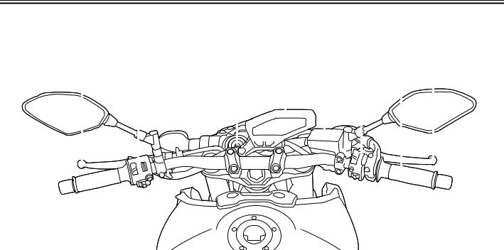
Controls and instruments
1 |
2 |
3 |
|
4 |
5 |
6 |
7 |
8 |
2 |
||||||||||||
|
|
|
|
|
|
|
|
|
|
|
|
|
|
|
|
|
|
|
|
|
|
|
|
|
|
|
|
|
|
|
|
|
|
|
|
|
|
|
|
|
|
|
|
|
|
|
|
|
|
|
|
|
|
|
|
|
|
|
|
|
|
|
|
|
|
|
|
|
|
|
|
|
|
|
|
|
|
|
|
|
|
|
|
|
|
|
|
|
|
|
|
|
|
|
|
|
|
|
|
|
|
|
|
|
|
|
|
|
|
|
|
|
|
|
|
|
|
|
|
|
|
|
|
|
|
|
|
|
|
|
|
|
|
|
|
|
|
|
|
|
|
|
|
|
|
|
|
|
|
|
|
|
|
|
|
|
|
|
|
|
|
|
|
|
|
|
|
|
|
|
|
|
|
|
|
|
|
|
|
|
|
|
|
|
|
|
|
|
|
|
|
|
|
|
|
|
|
|
|
|
|
|
|
|
|
|
|
|
|
|
|
|
|
|
|
|
|
|
|
|
|
|
|
|
|
|
|
|
|
|
|
|
|
|
|
|
|
|
|
|
|
1.Clutch lever (page 3-18)
2.Left handlebar switches (page 3-16)
3.Main switch/steering lock (page 3-2)
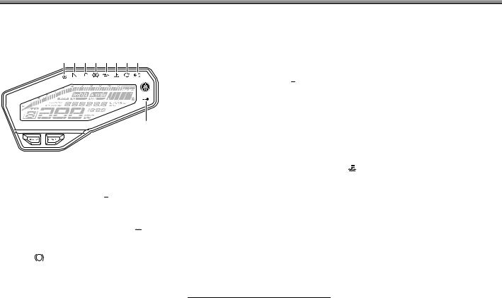
4.Multi-function meter unit (page 3-7)
5.Front brake fluid reservoir (page 6-21)
6.Right handlebar switches (page 3-16)
7.Throttle grip (page 6-15)
8.Brake lever (page 3-19)
2-3
Instrument and control functions
EAU10978
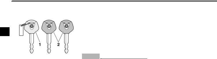
Immobilizer system
3
1.Code re-registering key (red bow)
2.Standard keys (black bow)
This vehicle is equipped with an immobilizer system to help prevent theft by re-registering codes in the standard keys. This system consists of the following:
a code re-registering key (with a red bow)
two standard keys (with a black bow) that can be re-registered with new codes
a transponder (which is installed in the code re-registering key)
an immobilizer unit
an ECU
an immobilizer system indicator
light (See page 3-6.)
The key with the red bow is used to register codes in each standard key. Since re-registering is a difficult process, take the vehicle along with all three keys to a Yamaha dealer to have them re-reg- istered. Do not use the key with the red bow for driving. It should only be used for re-registering the standard keys. Always use a standard key for driving.
ECA11822
NOTICE
DO NOT LOSE THE CODE RE-REGISTERING KEY! CONTACT YOUR DEALER IMMEDIATELY IF IT IS LOST! If the code re-registering key is lost, registering new codes in the standard keys is impossible. The standard keys can still be used to start the vehicle, however if code re-registering is required (i.e., if a new standard key is made or all keys are lost) the entire immobilizer system must be replaced. Therefore, it is highly recommended to use either standard key and keep the code re-registering key in a safe
place.
Do not submerse any key in water.
Do not expose any key to excessively high temperatures.
Do not place any key close to magnets (this includes, but not limited to, products such as speakers, etc.).
Do not place items that transmit electrical signals close to any key.
Do not place heavy items on any key.
Do not grind any key or alter its shape.
Do not disassemble the plastic part of any key.
Do not put two keys of any immobilizer system on the same key ring.
Keep the standard keys as well as keys of other immobilizer systems away from this vehicle’s code re-registering key.
Keep other immobilizer system keys away from the main switch as they may cause signal inter-
3-1
Instrument and control functions
ference. |
EAU10474 |
|
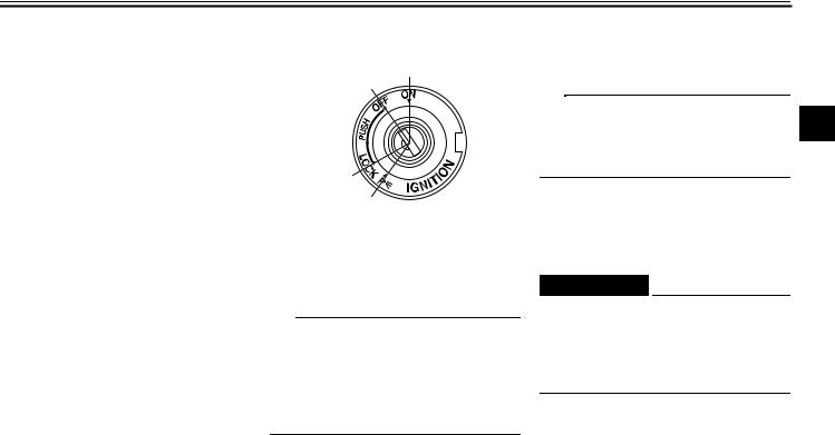
Main switch/steering lock |
|
|
|
OFF ON |
LOCK
P
The main switch/steering lock controls the ignition and lighting systems, and is used to lock the steering. The various positions are described below.
TIP
Be sure to use the standard key (black bow) for regular use of the vehicle. To minimize the risk of losing the code re-registering key (red bow), keep it in a safe place and only use it for code re-registering.
EAU36871
ON
All electrical circuits are supplied with power, the meter lighting, taillight, li-
cense plate light and auxiliary lights come on, and the engine can be started. The key cannot be removed.
TIP
The headlight comes on automatically when the engine is started and stays on 3 until the key is turned to “OFF”, even if
the engine stalls.
EAU10662
OFF
All electrical systems are off. The key can be removed.
EWA10062
 WARNING
Never turn the key to “OFF” or “LOCK” while the vehicle is moving. Otherwise the electrical systems will be switched off, which may result in loss of control or an accident.
EAU1068A
LOCK
The steering is locked and all electrical systems are off. The key can be removed.
3-2
Instrument and control functions
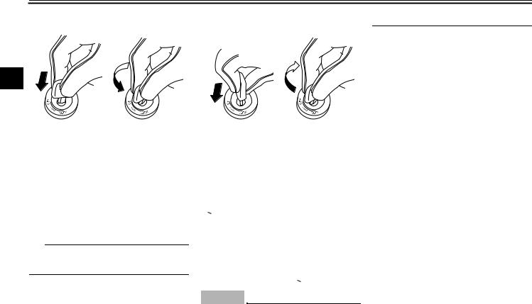
To lock the steering |
|
To unlock the steering |
may cause the battery to discharge. |
|
1 |
2 |
1 |
2 |
|
3
1.Push.
2.Turn.
1.Turn the handlebars all the way to the left.
2.With the key in the “OFF” position, push the key in and turn it to “LOCK”.
3.Remove the key.
TIP
If the steering will not lock, try turning the handlebars back to the right slightly.
1.Push.
2.Turn.
From the “LOCK” position, push the key and turn it to “OFF”.
EAU59680
 (Parking)
The hazard lights and turn signal lights can be turned on, but all other electrical systems are off. The key can be removed.
The steering must be locked before the key can be turned to “ ”.
”.
ECA20760
NOTICE
Using the hazard or turn signal lights for an extended length of time
3-3
Instrument and control functions
EAU49398
Indicator lights and warning lights
1 2 3 4 5 6 7 8
9
1.Traction control system indicator light “
 ” (for equipped models)
2.Neutral indicator light “  ”
”
3.High beam indicator light “  ”
”
4.Turn signal indicator light “
 ”
”
5.Oil level warning light “

 ”
”
6.Coolant temperature warning light “
 ”
”
7.Engine trouble warning light “ 
 ”
”
8.Anti-lock Brake System (ABS) warning light “ ABS ” (for ABS models)
9.Immobilizer system indicator light “ ”
”
EAU11022
Turn signal indicator light “
 ”
”
This indicator light flashes when a turn signal light is flashing.
EAU11061
Neutral indicator light “ ”
”
This indicator light comes on when the transmission is in the neutral position.
EAU11081
High beam indicator light “  ”
”
This indicator light comes on when the high beam of the headlight is switched on.
EAU11256
Oil level warning light “

 ”
”
This warning light comes on if the engine oil level is low.
The electrical circuit of the warning light can be checked by turning the key to “ON”. The warning light should come on for a few seconds and then go off.
If the warning light does not come on initially when the key is turned to “ON”, or if the warning light remains on after confirming that the oil level is correct (see page 6-9), have a Yamaha dealer check the vehicle.
TIP
Even if the oil level is sufficient, the warning light may flicker when riding on a slope or during sudden
acceleration or deceleration, but this is not a malfunction.
This model is equipped with a self-diagnosis device for the oil level detection circuit. If a problem
|
|
is detected in the oil level detection |
3 |
|
|
|
circuit, the oil level warning light |
||
|
|
|
||
|
|
will flash repeatedly. If this occurs, |
|
|
|
|
have a Yamaha dealer check the |
|
|
|
|
vehicle. |
|
|
|
|
|
|
|
|
|
EAU11447 |
|
|
Coolant temperature warning light |
|
|||
“ |
|
” |
|
|
|
|
|||
|
|
|||
This warning light comes on if the en- |
|
|||
gine overheats. If this occurs, stop the |
|
|||
engine immediately and allow the en- |
|
|||
gine to cool. |
|
|||
The electrical circuit of the warning light |
|
|||
can be checked by turning the key to |
|
|||
“ON”. The warning light should come |
|
|||
on for a few seconds, and then go off. |
|
|||
If the warning light does not come on |
|
|||
initially when the key is turned to “ON”, |
|
|||
or if the warning light remains on, have |
|
|||
a Yamaha dealer check the electrical |
|
|||
circuit. |
|
|||
3-4
Instrument and control functions
ECA10022
NOTICE
Do not continue to operate the engine if it is overheating.
3TIP
For radiator-fan-equipped vehicles, the radiator fan(s) automatically switch on or off according to the coolant temperature in the radiator.
If the engine overheats, see page 6-45 for further instructions.
EAU73500
Engine trouble warning light “ 
 ”
”
MT09
This warning light comes on if a problem is detected in the electrical circuit monitoring the engine. If this occurs, have a Yamaha dealer check the self-diagnosis system. (See page 3-14 for an explanation of the self-diagnosis mode.)
The electrical circuit of the warning light can be checked by turning the key to “ON”. The warning light should come
on for a few seconds, and then go off. If the warning light does not come on initially when the key is turned to “ON”, or if the warning light remains on, have a Yamaha dealer check the electrical circuit.
MT09A
This warning light comes on if a problem is detected in the engine or other vehicle control system. If this occurs, have a Yamaha dealer check the on-board diagnostic system.
The electrical circuit of the warning light can be checked by turning the key to “ON”. The warning light should come on for a few seconds, and then go off.
If the warning light does not come on initially when the key is turned to “ON”, or if the warning light remains on, have a Yamaha dealer check the vehicle.
EAU58530
ABS warning light “ ABS ” (for ABS models)
In normal operation, the ABS warning light comes on when the key is turned to “ON”, and goes off after traveling at a speed of 10 km/h (6 mi/h) or higher.
If the ABS warning light:
does not come on when the key is turned to “ON”
comes on or flashes while riding
does not go off after traveling at a speed of 10 km/h (6 mi/h) or higher
The ABS may not work correctly. If any of the above occurs, have a Yamaha dealer check the system as soon as possible. (See page 3-20 for an explanation of the ABS.)
EWA16041
 WARNING
If the ABS warning light does not go off after traveling at a speed of 10 km/h (6 mi/h) or higher, or if the warning light comes on or flashes while riding, the brake system reverts to conventional braking. If either of the above occurs, or if the warning light does not come on at all, use extra caution to avoid possible wheel lock during emergency braking. Have a Yamaha dealer check the brake system and electrical circuits as soon as possible.
3-5
Instrument and control functions
EAU73380
Traction control system indicator light “
 ” (for equipped models)
In normal operation, this indicator light flashes when traction control has engaged.
If the traction control system (page 3-21) becomes disabled while riding, this indicator light and the engine trouble warning light will come on.
The electrical circuit of this indicator light can be checked by turning the key to “ON”. The light should come on for a few seconds, and then go off.
If the light does not come on initially when the key is turned to “ON”, or if the light remains on, have a Yamaha dealer check the electrical circuit.
EAU73510
Immobilizer system indicator light “ ”
”
When the key is turned to “OFF” and 30 seconds have passed, the indicator light will flash steadily to indicate the immobilizer system is enabled. After 24 hours have passed, the indicator light will stop flashing, however the immobilizer system is still enabled.
The electrical circuit of the indicator light can be checked by turning the key to “ON”. The indicator light should come on for a few seconds, and then go off.
If the indicator light does not come on initially when the key is turned to “ON”, or if the indicator light remains on, have a Yamaha dealer check the vehicle.
MT09
The self-diagnosis device detects problems in the immobilizer system circuits. (See page 3-14 for an explanation of the self-diagnosis mode.)
MT09A
If a problem is detected in the immobilizer system, the indicator light will flash in a pattern. Have a Yamaha dealer check the vehicle.
TIP
If the immobilizer system indicator light flashes in the pattern, slowly 5 times then quickly 2 times, this could be caused by transponder interference. If this occurs, try the following.
1. Make sure there are no other im-
mobilizer keys close to the main switch. Other immobilizer system keys may cause signal interference and prevent the engine from starting.
2. Use the code re-registering key to 3 start the engine.
3.If the engine starts, turn it off, and try starting the engine with the standard keys.
4.If one or both of the standard keys do not start the engine, take the vehicle and all 3 keys to a Yamaha dealer to have the standard keys re-registered.
3-6
Instrument and control functions
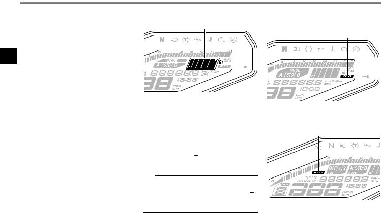
EAU73263 |
MT09 |
MT09A |
Multi-function meter unit |
1 |
2 |
3 |
4 |
5 |
1 |
2 |
3 |
4 |
5 |
6 |
|
3
|
|
|
|
|
|
8 |
7 |
6 |
9 |
8 |
7 |
|
1 |
2 |
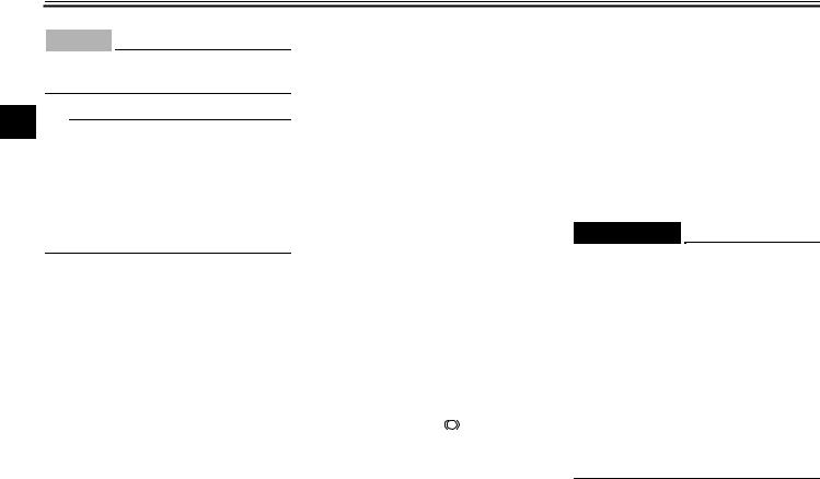
1. |
Transmission gear display |
|
1. |
Transmission gear display |
|
|
||
|
|
|
|
|
|
|
|
||||
1. |
“SELECT” button |
2. |
Tachometer |
|
2. |
Tachometer |
|
|
|||
2. |
“RESET” button |
3. |
Drive mode display |
|
3. |
Eco indicator “ECO” |
|
|
|||
|
|
|
|
|
4. |
Fuel meter |
|
4. |
TCS display |
|
|
|
|
|
|
|
5. |
Eco indicator “ECO” |
|
5. |
Drive mode display |
|
|
|
|
|
|
|
6. |
Multi-function display |
|
6. |
Fuel meter |
|
|
|
|
|
|
|
7. |
Clock |
|
7. |
Multi-function display |
|
|
|
|
|
|
|
8. |
Speedometer |
|
8. |
Clock |
|
|
|
|
|
|
|
|
|
|
9. |
Speedometer |
|
|
EWA12423
 WARNING
Be sure to stop the vehicle before making any setting changes to the multi-function meter unit. Changing settings while riding can distract the operator and increase the risk of an accident.
3-7
Instrument and control functions
The multi-function meter unit is equipped with the following:
a speedometer
a tachometer
a clock
a fuel meter
an eco indicator
a transmission gear display
a drive mode display
a TCS display (for equipped models)
a multi-function display
TIP
Except when switching to the brightness control mode or to display the clock, turn the key to “ON” before using the “SELECT” and “RESET” buttons to adjust the multi-function meter.
For the UK: To switch the speedometer and multi-function displays between kilometers and miles, press the “SELECT” button for one second.
Speedometer
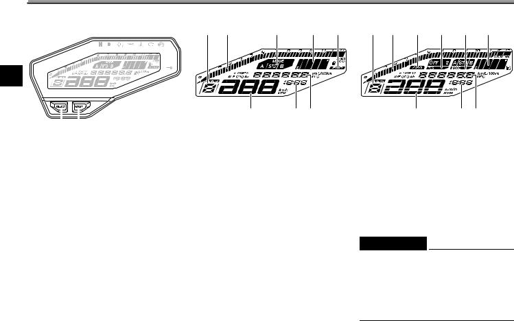
1
1. Speedometer
The speedometer shows the vehicle’s traveling speed.
Tachometer
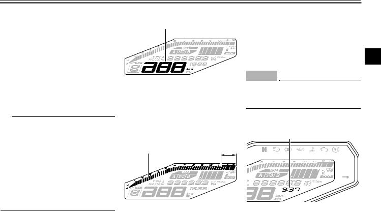
1 |
2 |
1.Tachometer
2.Tachometer red zone
The tachometer allows the rider to monitor the engine speed and keep it within the ideal power range.
When the key is turned to “ON”, the tachometer will sweep across the r/min range and then return to zero r/min in 3 order to test the electrical circuit.
ECA10032
NOTICE
Do not operate the engine in the tachometer red zone.
Red zone: 11250 r/min and above
Clock
1
1. Clock
The clock uses a 12-hour time system. When the key is not in the “ON” position, the clock can be viewed for 10
3-8
Instrument and control functions
seconds by pushing the “SELECT” button.
To set the clock
1. Turn the key to “ON”.
32. Push the “SELECT” button and “RESET” button together for two seconds.
3.When the hour digits start flashing, push the “RESET” button to set the hours.
4.Push the “SELECT” button, and the minute digits will start flashing.
5.Push the “RESET” button to set the minutes.
6.Push the “SELECT” button and then release it to start the clock.
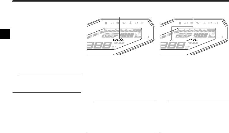
Fuel meter |
Eco indicator |
1 |
MT09 |
1
1. Fuel meter
The fuel meter indicates the amount of fuel in the fuel tank. The display segments of the fuel meter disappear towards “E” (empty) as the fuel level decreases. When the last segment starts flashing (“ ” will also flash for MT09), refuel as soon as possible.
TIP
If a problem is detected in the electrical ciruit, the fuel level segments and “ ” will flash repeatedly. If this occurs, have a Yamaha dealer check vehicle.
1. Eco indicator “ECO”
MT09A
1
1. Eco indicator “ECO”
This indicator comes on when the vehicle is being operated in an environmentally friendly, fuel-efficient manner. The
3-9
Instrument and control functions
indicator goes off when the vehicle is stopped.
TIP
Consider the following tips to reduce fuel consumption:
Avoid high engine speeds during acceleration.
Travel at a constant speed.
Select the transmission gear that is appropriate for the vehicle speed.
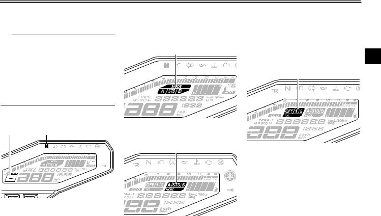
Transmission gear display
1 |
2 |
1.Transmission gear display
2.Neutral indicator light “  ”
”
This display shows the selected gear. The neutral position is indicated by “ ”
”
and by the neutral indicator light.
Drive mode display MT09
1
1. Drive mode display
MT09A
1
1. Drive mode display
This display indicates which drive
mode has been selected: “STD”, “A” or |
|
“B”. For more details on the modes and |
|
on how to select them, see pages 3-15 |
|
and 3-17. |
|
TCS display (for equipped models) |
3 |
|
|
MT09A |
|
1
1. TCS display
This display indicates which traction control system setting has been selected: “1”, “2” or “OFF”. For more details on the TCS settings and on how to select them, see page 3-21.
3-10
Instrument and control functions
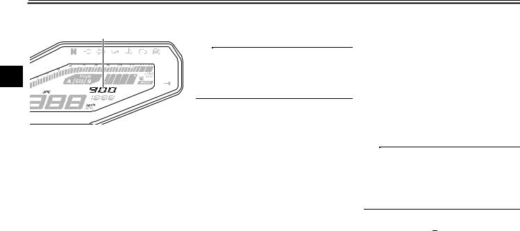
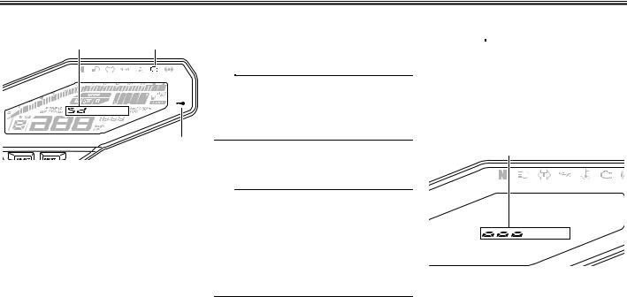
Multi-function display
1
3
1. Multi-function display
The multi-function display is equipped with the following:
an odometer
two tripmeters (which show the distance traveled since they were last reset)
a fuel reserve tripmeter (which shows the distance traveled since the last segment of the fuel meter started flashing)
an instantaneous fuel consumption display
an average fuel consumption display
a coolant temperature display
an air intake temperature display
self-diagnosis mode (MT09)
a brightness control display
TIP
The odometer will lock at 999999 and cannot be reset.
The tripmeters will lock at 9999.9 but can be manually reset.
Push the “SELECT” button to switch the display between the instantaneous fuel consumption mode “km/L” or “L/ 100 km”, average fuel consumption mode “AVE_ _._ km/L” or “AVE_ _._ L/ 100 km”, coolant temperature mode “ C”, air intake temperature mode “Air_ _ C”, odometer mode “ODO”, and tripmeter modes “TRIP 1” and “TRIP 2” in the following order:
km/L or L/100 km AVE_ _._ km/L or AVE_ _._ L/100 km C Air_ _ CODO TRIP 1 TRIP 2
For the UK:
Push the “SELECT” button to switch the display between the instantaneous fuel consumption mode “km/L”, “L/100 km” or “MPG”, average fuel consumption mode “AVE_ _._ km/L”, “AVE_ _._
L/100 km” or “AVE_ _._ MPG”, coolant temperature mode “ C”, air intake temperature mode “Air_ _ C”, odometer mode “ODO”, and tripmeter modes “TRIP 1” and “TRIP 2” in the following order:
km/L, L/100 km or MPG AVE_ _._ km/L, AVE_ _._ L/100 km or AVE_ _._ MPG C Air_ _ C ODO TRIP 1 TRIP 2
TIP
Push the “RESET” button to switch the display in the reverse order.
The fuel reserve tripmeter and self-diagnosis modes come on automatically.
If the last segment of the fuel meter starts flashing (“ ” will also flash for MT09), the display automatically changes to the fuel reserve tripmeter mode “F-TRIP” and starts counting the distance traveled from that point. In this case, push the “SELECT” button to switch the display in the following order:
F-TRIP km/L or L/100 km AVE_ _._ km/L or AVE_ _._ L/100 km C
3-11
Instrument and control functions
Air_ _ C ODO TRIP 1 TRIP 2 F-TRIP
For the UK:
F-TRIP km/L, L/100 km or MPG AVE_ _._ km/L, AVE_ _._ L/100 km or AVE_ _._ MPG C Air_ _ C ODO TRIP 1 TRIP 2 F-TRIP
TIP
To reset a tripmeter, select it by pushing the “SELECT” button, and then push the “RESET” button for one second.
If you do not reset the fuel reserve tripmeter manually, it resets automatically and disappears after refueling and traveling 5 km (3 mi).
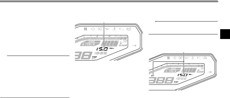
Instantaneous fuel consumption mode
1
1. Instantaneous fuel consumption display
The instantaneous fuel consumption display can be set to either “km/L”, “L/ 100 km” or “MPG” (for the UK).
“km/L”: The distance that can be traveled on 1.0 L of fuel under the current riding conditions is shown.
“L/100 km”: The amount of fuel necessary to travel 100 km under the current riding conditions is shown.
“MPG” (for the UK): The distance
that can be traveled on 1.0 Imp.gal of fuel under the current riding conditions is shown.
To switch between the instantaneous
fuel consumption display settings, push the “SELECT” button for one second.
TIP
If traveling at speeds under 20 km/h (12
mi/h), “_ _._” is displayed.
3
Average fuel consumption mode
1 |
1. Average fuel consumption display
This display shows the average fuel consumption since it was last reset. The average fuel consumption display can be set to either “AVE_ _._ km/L”, “AVE_ _._ L/100 km” or “AVE_ _._ MPG” (for the UK).
“AVE_ _._ km/L”: The average distance that can be traveled on 1.0 L of fuel is shown.
3-12
Instrument and control functions
“AVE_ _._ L/100 km”: The average amount of fuel necessary to travel 100 km is shown.
“AVE_ _._ MPG” (for the UK): The average distance that can be trav-
3eled on 1.0 Imp.gal of fuel is shown.
To switch between the average fuel consumption display settings, push the “SELECT” button for one second.
To reset the average fuel consumption, push the “RESET” button for one second.
TIP
After resetting the average fuel consumption, “_ _._” will be shown until the vehicle has traveled 1 km (0.6 mi).
Coolant temperature mode
1
1. Coolant temperature display
This display shows the coolant temperature from 40 C to 116 C in 1 C increments.
If the message “HI” flashes, stop the vehicle, then stop the engine, and let the engine cool. (See page 6-45.)
TIP
When the coolant temperature is below 40 C, “LO” will be displayed.
The coolant temperature varies with changes in the weather and engine load.
Air intake temperature mode
1 |
1. Air intake temperature display
The air intake temperature display indicates the temperature of the air drawn into the air filter case.
This display shows the air intake temperature from –9 C to 99 C in 1 C increments.
TIP
–9 C will be displayed even if the
air intake temperature falls below –9 C.
The air intake temperature may vary from the ambient temperature.
3-13
Instrument and control functions
Self-diagnosis mode (MT09)
1 |
2 |
lizer system circuits, the immobilizer system indicator light will flash and the display will indicate an error code.
TIP
If the display indicates error code 52, this could be caused by transponder interference. If this error code appears, try the following.
|
|
ECA11591 |
|
|
NOTICE |
|
|
|
|
If the display indicates an error |
|
|||
code, the vehicle should be checked |
|
|||
as soon as possible in order to avoid |
|
|||
engine damage. |
3 |
|||
|
|
|
|
|
Brightness control mode |
|
|||
|
||||
3
1.Error code display
2.Engine trouble warning light “ 
 ”
”
3.Immobilizer system indicator light “ ”
”
This model is equipped with a self-diag- nosis device for various electrical circuits.
If a problem is detected in any of those circuits, the engine trouble warning light will come on and the display will indicate an error code.
If the display indicates any error codes, note the code number, and then have a Yamaha dealer check the vehicle.
The self-diagnosis device also detects problems in the immobilizer system circuits.
If a problem is detected in the immobi-
1.Use the code re-registering key to start the engine.
TIP
Make sure there are no other immobilizer keys close to the main switch, and do not keep more than one immobilizer key on the same key ring! Immobilizer system keys may cause signal interference, which may prevent the engine from starting.
2.If the engine starts, turn it off and try starting the engine with the standard keys.
3.If one or both of the standard keys do not start the engine, take the vehicle, the code re-registering key and both standard keys to a Yamaha dealer and have the standard keys re-registered.
1
1. Brightness level display
The brightness of the multi-function meter unit panel can be adjusted.
To adjust the brightness
1.Turn the key to “OFF”.
2.While pushing the “SELECT” button, turn the key to “ON” and continue pushing the button until the display switches to the brightness
3-14
Instrument and control functions
control mode.
3.Push the “RESET” button to set the brightness level.
4.Push the “SELECT” button to confirm the selected brightness level
3and exit the brightness control mode.
EAU47634
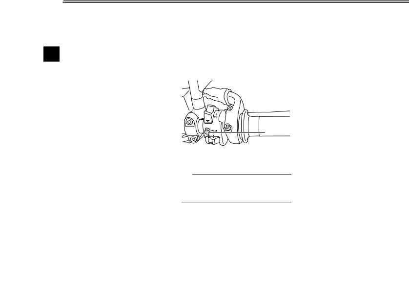
D-mode (drive mode)
D-mode is an electronically controlled engine performance system with three mode selections (“STD”, “A”, and “B”). Push the drive mode switch “MODE” to switch between modes. (See page 3-17 for an explanation of the drive mode switch.)
1
This mode allows the rider to enjoy smooth and sporty drivability from the low-speed range to the high-speed range.
Mode “A”
Mode “A” offers a sportier engine response in the lowto mid-speed range compared to mode “STD”.
Mode “B”
Mode “B” offers response that is somewhat less sharp compared to mode “STD” for riding situations that require especially sensitive throttle operation.
1. Drive mode switch “MODE”
TIP
Before using D-mode, make sure you understand its operation along with the operation of the drive mode switch.
Mode “STD”
Mode “STD” is suitable for various riding conditions.
3-15
 Loading...