


MIXING CONSOLE
Owner’s Manual
Thank you for purchasing the YAMAHA MX12/6 or MX20/6 Mixing Console. Both the MX12/6 and MX20/6 mixers are designed to provide the user with an ideal balance of operability, functionality, and simplicity.
In order to get the most out of your MX12/6 or MX20/6 mixer and its functions, and to enjoy years of trouble-free use, please read this Owner’s Manual thoroughly and keep it in a safe place for future reference.
Features
•The MX12/6 offers 12 input channels that can be mixed into stereo, monaural, or to four group outputs.
•The MX20/6 offers 20 input channels that can be mixed into stereo, monaural, or to four group outputs.
•A C-R/PHONES jack offers easy connection to a sub amp for monitoring. It allows monitoring of the main stereo output, TAPE IN input and the signals from groups 1/2, 3/4.
•The mixer is equipped with a highly efficient, built-in digital effects section. The built-in effects allow you to create professional sounding mixes without the need of additional equipment. An EFFECT SEND jack is also supplied to allow the use of external effectors.
•Two AUX SEND/RETURN jacks are provided. Two separate AUX buses can be used as sends for external effectors or a monitor system.
•The mixer supplies phantom power to provide easy connection of condenser microphones that require an external power source.
•The mixer is equipped with INSERT I/O jacks for input channels 1-4 (MX12/6) or 1-8 (MX20/6) allowing individual effects to be inserted into individual channels.
•Both XLR type mic input jacks and TRS phone line input jacks are provided on channels 1-8 (MX12/6) or 1-16 (MX20/ 6). Input channels 9-12 (MX12/6) or 17-20 (MX20/6) are equipped with stereo line input jacks. The MX12/6 and MX20/6 can handle a wide range of sources, from microphones to line level devices and stereo output synthesizers.
•TAPE IN jacks and REC OUT jacks offer easy connection of tape decks for playback and recording.
Contents |
|
Front & Rear Panels ............................ |
2 |
Channel Control Section ........................ |
2 |
Master Control Section .......................... |
4 |
Connector Section ................................. |
6 |
Rear Panel ............................................. |
7 |
Applications ............................................ |
9 |
Supplement .......................................... |
11 |
Specifications ....................................... |
11 |
Dimensions .......................................... |
12 |
Block and Level Diagrams .................... |
13 |
Keep This Manual For Future Reference.

FCC INFORMATION (U.S.A.)
1.IMPORTANT NOTICE: DO NOT MODIFY THIS UNIT! This product, when installed as indicated in the instructions contained in this manual, meets FCC requirements. Modifications not expressly approved by Yamaha may void your authority, granted by the FCC, to use the product.
2.IMPORTANT: When connecting this product to accessories and/or another product use only high quality shielded cables. Cable/s supplied with this product MUST be used. Follow all installation instructions. Failure to follow instructions could void your FCC authorization to use this product in the USA.
3.NOTE: This product has been tested and found to comply with the requirements listed in FCC Regulations, Part 15 for Class “B” digital devices. Compliance with these requirements provides a reasonable level of assurance that your use of this product in a residential environment will not result in harmful interference with other electronic devices. This equipment generates/uses radio frequencies and, if not installed and used according to the instructions found in the users manual, may cause interference harmful to the operation of other electronic devices. Compliance with FCC regulations does not guarantee that interference will not occur in all installations. If this product is found to be the source of interference, which can be determined by turning the unit “OFF” and “ON”, please try to eliminate the problem by using one of the following measures: Relocate either this product or the device that is being affected by the interference. Utilize power outlets that are on different branch (circuit breaker or fuse) circuits or install AC line filter/s. In the case of radio or TV interference, relocate/reorient the antenna. If the antenna lead-in is 300 ohm ribbon lead, change the lead-in to coaxial type cable. If these corrective measures do not produce satisfactory results, please contact the local retailer authorized to distribute this type of product. If you can not locate the appropriate retailer, please contact Yamaha Corporation of America, Electronic Service Division, 6600 Orangethorpe Ave, Buena Park, CA 90620
The above statements apply ONLY to those products distributed by Yamaha Corporation of America or its subsidiaries.
WARNING: THIS APPARATUS MUST BE EARTHED
IMPORTANT
THE WIRES IN THIS MAINS LEAD ARE COLOURED IN
ACCORDANCE WITH THE FOLLOWING CODE:
GREEN-AND-YELLOW : EARTH
BLUE : NEUTRAL
BROWN : LIVE
As the colours of the wires in the mains lead of this apparatus may not correspond with the coloured markings identifying the terminals in your plug, proceed as follows:
The wire which is coloured GREEN and YELLOW must be connected to the terminal in the plug which is marked by the letter E or by the safety earth symbol  or coloured GREEN and YELLOW.
The wire which is coloured BLUE must be connected to the terminal which is marked with the letter N or coloured BLACK.
The wire which is coloured BROWN must be connected to the terminal which is marked with the letter L or coloured RED.
*This applies only to products distributed by YAMAHA KEMBLE MUSIC (U.K.) LTD.
MX12/6, 20/6 — Owner’s Manual

Important 1
Important
Read the following before operating the MX12/6, 20/6
Warnings
•Do not place a container with liquid or small metal objects on top of this unit. Liquid or metal objects inside this unit are a fire and electrical shock hazard.
•Do not allow water to enter this unit or allow the unit to become wet. Fire or electrical shock may result.
•Connect this unit’s power cord only to an AC outlet of the type stated in this Owner’s Manual or as marked on the unit. Failure to do so is a fire and electrical shock hazard.
•Do not scratch, bend, twist, pull, or heat the power cord. A damaged power cord is a fire and electrical shock hazard.
•Do not place heavy objects, including this unit, on top of the power cord. A damaged power cord is a fire and electrical shock hazard. In particular, be careful not to place heavy objects on a power cord covered by a carpet.
•If you notice any abnormality, such as smoke, odor, or noise, or if a foreign object or liquid gets inside the unit, turn it off immediately. Remove the power cord from the AC outlet. Consult your dealer for repair. Using the unit in this condition is a fire and electrical shock hazard.
•Should this unit be dropped or the cabinet be damaged, turn the power switch off, remove the power plug from the AC outlet, and contact your dealer. If you continue using the unit without heeding this instruction, fire or electrical shock may result.
•If the power cord is damaged (i.e., cut or a bare wire is exposed), ask your dealer for a replacement. Using the unit with a damaged power cord is a fire and electrical shock hazard.
•Do not remove the unit’s cover. You could receive an electrical shock. If you think internal inspection, maintenance, or repair is necessary, contact your dealer.
•Do not modify the unit. Doing so is a fire and electrical shock hazard.
•If lightning begins to occur, turn off the power switch of the unit as soon as possible, and unplug the power cable plug from the electrical outlet.
•If there is a possibility of lightning, do not touch the power cable plug if it is still connected. Doing so may be an electrical shock hazard.
Cautions
•Hold the power cord plug when disconnecting it from an AC outlet. Never pull the cord. A damaged power cord is a potential fire and electrical shock hazard.
•Do not touch the power plug with wet hands. Doing so is a potential electrical shock hazard.
Operating Notes
•Using a mobile telephone near this unit may induce noise. If noise occurs, use the telephone away from the unit.
•XLR-type connectors are wired as follows:
pin 1: ground, pin 2: hot (+), and pin 3: cold (-).
•Insert TRS phone jacks are wired as follows: sleeve: ground, tip: send, and ring: return.
•The performance of components with moving contacts, such switches, rotary controls, faders, and connectors, deteriorates over time. The rate of deterioration depends on the operating environment and is unavoidable. Consult your dealer about replacing defective components.
MX12/6, 20/6 — Owner’s Manual

2 Front & Rear Panels
Front & Rear Panels
Channel Control Section
|
Channels |
Channels |
|
q GAIN Control |
|
|
|
|||
|
1-8 (MX12/6) |
9-12 (MX12/6) |
|
Adjusts the input level of the signal entering the mixer to an |
|
|||||
|
1-16 (MX20/6) |
17-20 (MX20/6) |
|
|
||||||
|
|
optimum level. |
|
|
|
|
||||
|
(Monaural) |
(Stereo) |
|
|
|
|
|
|||
|
|
To obtain an optimum balance between the S/N ratio and |
|
|||||||
|
|
|
|
|
||||||
|
|
|
|
dynamic range, adjust the level so that the peak indicator w |
|
|||||
|
q |
|
|
occasionally lights. |
|
|
|
|||
|
w |
|
|
-60 to -16 indicates the MIC input adjustment level, -34 to +10 |
||||||
|
|
|
indicates the LINE input adjustment level. |
|
|
|||||
|
|
|
|
w PEAK Indicator |
|
|
|
|||
|
|
|
|
The indicator detects peaks in the signal after it has passed the |
||||||
|
|
|
|
EQ. |
|
|
|
|
|
|
|
e |
|
|
The indicator will light red when the level reaches +17dB to |
|
|||||
|
|
|
|
warn that clipping is imminent. |
|
|
|
|||
|
|
|
|
e Equalizer |
|
|
|
|
|
|
|
|
|
|
Provides +/-15dB of control over high, mid and low frequency |
||||||
|
|
|
|
ranges at the center frequencies listed below. |
|
|
||||
r |
r |
|
|
|
HIGH |
: |
10kHz (shelving) |
|
|
|
|
t |
|
t |
|
MID |
: |
2.5 kHz (peaking) |
|
|
|
|
|
|
LOW |
: |
100Hz (shelving) |
|
|
|
||
|
|
|
|
|
|
|
|
|||
|
|
|
|
Frequency response will be flat when the knob is positioned at |
||||||
|
|
|
|
“G”. |
|
|
|
|
|
|
|
y |
|
|
|
+20 |
|
|
|
|
|
|
|
|
|
|
+15 |
|
|
|
|
|
|
u |
|
|
|
+10 |
|
|
|
|
|
|
|
|
[dB] |
|
|
|
|
|
|
|
|
|
|
|
+5 |
|
|
|
|
|
|
|
|
|
|
|
|
|
|
|
|
|
|
|
|
|
Response |
0 |
|
|
|
|
|
|
i |
|
i |
–5 |
|
|
|
|
|
|
|
|
|
|
|
|
|
|
|||
|
|
|
–10 |
|
|
|
|
|
||
|
|
|
|
|
|
|
|
|
|
|
|
|
|
|
|
–15 |
|
|
|
|
|
|
|
|
|
|
–20 |
|
100 |
1k |
10k |
20k |
|
|
|
|
|
20 |
|
||||
|
|
|
|
|
|
|
Frequency [Hz] |
|
|
|
o
The MX12/6’s panel is used for all following illustrations in this manual.
r AUX1, AUX2 Controls t POST Switch
Individually controls the level of the signal sent from each channel to the AUX1 and AUX2 buses.
The signal taken from before the channel fader is sent to AUX1.
Depending upon the POST switch setting, the signal taken from either before (POST Switch = ?) or after (POST Switch = >) the channel fader is sent to AUX2.
When a stereo channel is used, L and R signals are combined and sent to the AUX1 and AUX2 buses.
MX12/6, 20/6 — Owner’s Manual
Front & Rear Panels 3
y EFFECT Control
Controls the level of the signal sent from each channel to the EFFECT bus.
This control is located after the channel fader so its level will also be affected by the channel fader setting.
When a stereo channel is used, L and R channel signals are combined and sent to the EFFECT bus.
u PAN Control (MX12/6:CH1-8, MX20/6:CH1-16)
BAL Control (MX12/6:CH9-12, MX20/6:CH17-20)
The PAN control knobs set the position within the stereo field of each signal that is sent to the GROUP bus 1-2, GROUP bus 3-4 and STEREO bus L-R.
The BAL control knobs set the balance between left and right channels and assigns the signals that are received at INPUT L (MX12/6:CH9, 11, MX20/6:CH17, 19) to GROUP buses 1/3 or STEREO bus L, and the signals received at INPUT R (MX12/6:CH10, 12, MX20/6:CH18, 20) to GROUP buses 2/4 or STEREO bus R.
i GROUP, ST Select Switches
Used to send the signal of each channel to the GROUP bus 1-2, GROUP bus 3-4 and STEREO bus L-R.
When the switch is ON (>), the signal is sent to the relative bus.
o Channel Fader
Controls the output level of the input channel signal and adjusts the volume balance between channels.
* Levels of unused faders should be lowered.
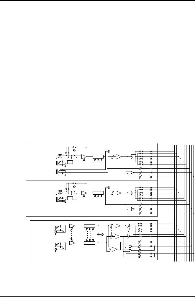
|
L R |
|
GROUP1 GROUP2 GROUP3 GROUP4 |
STEREO STEREO |
AUX1 AUX2 EFFECT |
from DC Power Supply
|
MIC INPUT |
|
[-60~-16dB] |
CH INPUT |
LINE INPUT |
MX12/6:1~4ch |
[-34~+10dB] |
MX20/6:1~8ch |
|
|
INSERT I/O |
|
[0dB] |
|
PHANTOM |
|
|
|
|
PEAK |
|
[0dB] |
|
(8ch/sw) |
|
|
|
|
PAN |
1-2 |
|
|
|
|
|
|
|
|
||
|
|
[0dB] |
|
|
|
|
|
|
|
HA |
3-Stage EQ |
BA |
[0dB] |
|
|||
|
|
|
3-4 |
|||||
|
|
|
|
|
|
|
|
|
PAD |
GAIN |
|
Lo |
Mid |
Hi |
Ch.Fader |
|
|
|
[-10dB] |
|
ST |
|||||
|
[-60dB~-16dB] |
|
|
|
|
|
|
|
|
[-34dB~+10dB] |
|
|
|
|
|
[-6dB] |
|
|
|
|
|
|
|
|
|
|
|
|
|
|
|
|
|
|
AUX1 |
POST AUX2
EFFECT
|
|
|
|
from DC Power Supply |
|
|
|
|||
|
|
|
PHANTOM |
|
|
|
|
PEAK |
|
[0dB] |
|
|
|
(8ch/sw) |
|
|
|
|
PAN |
1-2 |
|
|
MIC INPUT |
|
|
|
|
|
|
|
||
|
|
|
|
|
|
|
|
|
||
|
[-60~-16dB] |
|
HA |
[0dB] |
3-Stage EQ |
BA |
[0dB] |
|
||
|
|
|
|
|
3-4 |
|||||
|
|
|
|
|
|
|
|
|
|
|
CH INPUT |
LINE INPUT |
PAD |
|
|
Lo |
Mid |
Hi |
Ch.Fader |
|
|
GAIN |
|
[-10dB] |
|
|
||||||
MX12/6:5~8ch |
[-34~+10dB] |
|
|
ST |
||||||
MX20/6:9~16ch |
|
|
[-60dB~-16dB] |
|
|
|
|
|
|
|
|
|
|
[-34dB~+10dB] |
|
|
|
|
|
[-6dB] |
|
|
|
|
|
|
|
|
|
|
|
|
AUX1
POST AUX2
EFFECT
L
ST INPUT
MX12/6: 9/10ch, 11/12ch
MX20/6:17/18ch, 19/20ch
[-34~+10dB]
R
HA |
[0dB] |
|
|
|
3-Stage EQ |
|
|||
|
Lo |
Mid |
Hi |
PEAK |
|
GAIN |
|
|
|
|
[-34dB~+10dB] |
|
|
|
HA |
3-Stage EQ |
|
||
|
[0dB] |
|
[0dB] |
|
1-2 |
BA |
|
|
ST Ch.Fader |
BAL |
3-4 |
|
||
[-10dB] |
|
|
BA |
|
ST |
|
|
|
|
|
[-6dB] |
|
|
AUX1 |
SUM |
POST |
AUX2 |
|
||
|
|
|
|
|
EFFECT |
MX12/6, 20/6 — Owner’s Manual
 Loading...