


 Loading...
Phaser 5500/5550 Service Documentation
705P01216 March 2008

Phaser® 5500/5550 Printer
Service Manual
Phaser 5500/5550 Printer
705P01216
Initial Issue
March 2008
Xerox Corporation
XOG Worldwide Product Training and Information
26600 W Parkway
Wilsonville, OR 97070
NOTICE: All service documentation is supplied to Xerox external customers for informational purpose only. Xerox service documentation is intended for use by certified, product trained service personnel only. Xerox does not warrant or represent that such documentation is complete, nor does Xerox represent or warrant that it will notify or provide to such customer any future changes to this documentation. Customer performed service of equipment, or modules, components or parts of such equipment may affect the warranty offered by Xerox with respect to such equipment. You should consult the applicable warranty for its terms regarding customer or third party provided service. If the customer services such equipment, modules, components or parts thereof, the customer releases Xerox from any and all liability for the customer actions, and the customer agrees to indemnify, defend and hold Xerox harmless from any third party claims which arise directly or indirectly from such service.
Unpublished rights reserved under the copyright laws of the United States. Contents of this publication may not be reproduced in any form without permission of Xerox Corporation.
Copyright protection claimed includes all forms and matters of copyrightable materials and information now allowed by statutory or judicial law or hereinafter granted, including without limitation, material generated from the software programs which are displayed on the screen such as styles, templates, icons, screen displays, looks, etc.
Xerox technical training materials and service manuals are intended for use by authorized Xerox service technicians and service partners only and are not for resale. These materials may not be distributed, copied, or otherwise reproduced without prior written consent from Xerox Corporation.
XEROX®, CentreWare®, Phaser®, PhaserCal®, PhaserMatch®, PhaserSMART®, TekColor™, PrintingScout™, and Walk-Up® are trademarks of Xerox Corporation in the United States and/or other countries.
Adobe® and PostScript® are trademarks of Adobe Systems Incorporated in the United States and/or other countries.
Apple®, Bonjour®, ColorSync®, EtherTalk®, Macintosh®, and Mac OS® are trademarks of Apple Computer, Inc. in the United States and/or other countries.
PCL® is a trademark of Hewlett-Packard Corporation in the United States and/or other countries.
Microsoft®, Vista™, Windows®, and Windows Server™ are trademarks of Microsoft Corporation in the United States and/or other countries.
Novell®, NetWare®, and IPX/SPX™ are trademarks of Novell, Incorporated in the United States and/or other countries.
SunSM, Sun Microsystems™, and Solaris™ are trademarks of Sun Microsystems, Incorporated in the United States and/or other countries.
UNIX® is a registered trademark in the United States and other countries, licensed exclusively through X/Open Company Limited.
As an ENERGY STAR® partner, Xerox Corporation has determined that this product meets ENERGY STAR guidelines for energy efficiency. The ENERGY STAR name and logo are registered U.S. marks.
PANTONE® Colors generated may not match PANTONE-identified standards. Consult current PANTONE Publications for accurate color. PANTONE® and other Pantone, Inc. trademarks are the property of Pantone, Inc. © Pantone, Inc., 2000.
Initial Issue |
03/05/2008 |
|
|
Phaser 5500/5550 Printer Service Manual |
|

Introduction
About this Manual ........................................................................................................... |
iii |
Organization.................................................................................................................... |
iii |
How to Use this Documentation...................................................................................... |
iv |
Power Safety Precautions............................................................................................... |
vi |
Service Safety Summary................................................................................................. |
vii |
Electrostatic Discharge Precautions ............................................................................... |
viii |
Service Terms ................................................................................................................. |
ix |
Symbology and Nomenclature ........................................................................................ |
x |
Regulatory Specifications................................................................................................ |
xiii |
Phaser 5500/5550 Printer Overview ............................................................................... |
xiv |
Phaser 5500/5550 Printer Configurations ....................................................................... |
xiv |
Parts of the Printer .......................................................................................................... |
xv |
Printer Options ................................................................................................................ |
xvi |
Consumables and Routine Maintenance Items .............................................................. |
xviii |
Printer Specifications ...................................................................................................... |
xix |
Phaser 5500/5550 Printer Menu Map ............................................................................. |
xxi |
Initial Issue |
March 2008 |
Introduction |
|
|
|
Phaser® 5500/5550 Printer |
i |
|

About this Manual
The Phaser 5500//5550 Printer Service Manual is the primary document used for diagnosing, repairing, maintaining, and troubleshooting the printer. It is the controlling publication for a service call. Information on its use is found in the introduction of the Service Manual.
To ensure complete understanding of this product, participation in Xerox Phaser 5500/5550 Service Training is strongly recommended. To service this product, Xerox certification for this product is required.
Organization
The titles of the sections and a description of the information contained in each section are contained in the following paragraphs:
Introduction and General Information
This section contains documentation organization, symbology and nomenclature, translated warnings, safety symbols, regulatory specifications, and general information.
Service Manual Revision
Updates are issued as the system changes or as corrections are identified.
For updates to the Service Manual, Service Bulletins, Knowledge Base, etc., go to:
•Xerox Global Service Net - https://www.xrxgsn.com
•Service Partners - http://www.office.xerox.com/partners
For further technical support, contact your assigned Xerox Technical Support for this product.
Section 1 - Service Call Procedures
This section contains procedures to be taken during a service call on the machine and in what sequence they are to be completed. This is the entry level for all service calls.
Section 2 - Status Indicator RAPs
This section contains the diagnostic aids for troubleshooting the Fault Code and non-Fault Code related faults (with the exception of image quality problems).
Section 3 - Image Quality
This section contains the diagnostic aids for troubleshooting any image quality problems, as well as image quality specifications and image defect samples.
Section 4 - Repairs and Adjustments
This section contains all the removal, replacement, and adjustment procedures.
Repairs
Repairs include procedures for removal and replacement of spare parts listed in the Parts List. Use the repair procedures for the correct order of removal and replacement, for warning, cautions, and notes.
Adjustments
Adjustments include procedures for adjusting the parts that must be within specification for the correct operation of the system. Use the adjustment procedures for the correct sequence of operation for specifications, warnings, cautions, and notes.
Section 5 - Parts List
This section contains the illustrated Parts List.
Section 6 - General Troubleshooting
This section contains details of embedded Service Diagnostics tests, as well as troubleshooting procedures for system problems not related to a specific fault code.
Section 7 - Wiring Data
This section contains drawings, lists of Plug/Jack locations, and diagrams of the power distribution wire networks in the machine. This section also contains the Block Schematic Diagrams.
Section 8 - Theory of Operation
This section contains detailed functional information on the print engine components.
Initial Issue |
March 2008 |
Introduction |
|
About this Manual, Organization |
|
Phaser® 5500/5550 Printer |
iii |
How to Use this Documentation
The Service Call Procedures in section 1 describe the sequence of activities used during the service call. The call must be entered using these procedures.
Use of the Circuit Diagrams
Circuit Diagrams (CDs) are included in Section 7 of the Service Manual. All wirenets, with the exception of power distribution wirenets, are shown on the CDs. The power distribution wirenets on the CDs will end at the terminal board for the power being distributed. Find the wirenet for that power and locate the terminal board on the wirenet. Use the wirenet to troubleshoot any power distribution wiring not shown on the CD.
Use of the Block Schematic Diagrams
Block Schematic Diagrams (BSDs) are included in Section 7 (Wiring Data) of the Service Manual. The BSDs provide the functional relationship of the electrical circuitry to any mechanical, or non-mechanical, inputs or outputs throughout the machine. Inputs and outputs such as motor drive, mechanical linkages, operator actions, and air flow are shown. The BSDs provides an overall view of how the entire subsystem works.
The BSDs do not contain an Input Power Block referring to Chain 1. It will be necessary to refer to the Wirenets in order to trace a wire back to its source.
Notations Used in Wiring Diagrams
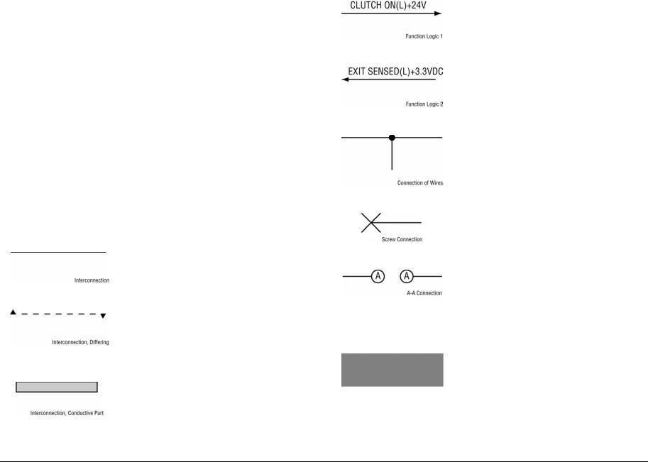
The symbols in the interconnection wiring diagrams are described below. Note that the description of general symbols is omitted.
Table 1 Symbols Used in Wiring Diagrams |
|
Symbol |
Description |
|
|
|
Represents an interconnection between parts using wir- |
|
ing harness or wire, and indicates its signal name/con- |
|
tents. The arrow “>” or “<” on the line represents the |
|
direction of signal flow. |
Figure 1 Interconnection |
|
|
|
|
Represents an interconnection between parts using wir- |
|
ing harness or wire, which differs according to the specifi- |
|
cations, and indicates its signal name/contents. The |
|
arrow “>” or “<” on the line represents the direction of sig- |
|
nal flow. |
Figure 2 Interconnection Differ- |
|
ence |
|
|
|
|
Represents a connection between parts using a conduc- |
|
tive member such as a plate spring, and indicates its sig- |
|
nal name/contents. The arrow “>” or “<” on the line |
|
represents the direction of signal flow. |
Figure 3 Conductive Parts |
|
|
|
Table 1 Symbols Used in Wiring Diagrams |
|
Symbol |
Description |
|
|
|
Represents a function and a logical value (High (H) or |
|
Low (L)) of a signal when the function is activated. The |
|
voltage indicates a value when the signal is High. The |
|
arrow indicates the direction of signal flow. |
Figure 4 Function Activated |
|
|
|
|
Represents a function and a logical value (High (H) or |
|
Low (L)) of a signal when the function is in a detectable |
|
state. The voltage indicates a value when the signal is |
|
High. The arrow indicates the direction of signal flow. |
Figure 5 Function Detectable |
|
|
|
|
Represents a connection between lead wires. |
Figure 6 Lead Wires Connection |
|
|
|
|
Represents a connection between parts by tightening of |
|
a screw. |
Figure 7 Screw Connection |
|
|
|
|
Represents a connection between “A” and “A.” |
Figure 8 Point Connection |
|
|
|
24 VDC |
The DC voltage indicates an approximate value mea- |
|
sured when the negative side is connected to a signal |
|
ground (SG). |
|
|
|
Indicates a signal ground (SG). |
Figure 9 Signal Ground |
|
|
|
Introduction |
March 2008 |
Initial Issue |
How to Use this Documentation |
|
|
iv |
Phaser® 5500/5550 Printer |
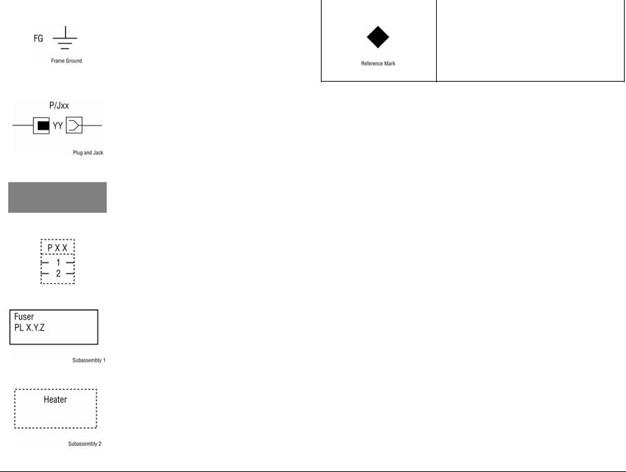
Table 1 Symbols Used in Wiring Diagrams |
|
Symbol |
Description |
|
|
|
Indicates a frame ground (FG). |
Figure 10 Frame Ground |
|
|
|
RTN |
Indicates a return. |
|
|
|
Represents a connector. The connector and PIN Nos. |
|
are shown at the upper and lower parts respectively.“P,-” |
|
indicates the plug side of the connector.“J,>” indicates |
|
the jack side of the connector. |
Figure 11 Plug and Jack |
|
|
|
|
Represents a connection terminal with a plate spring on |
|
the printed circuit board. The connector No. is indicated |
|
inside the box. |
Figure 12 Connection Terminal |
|
|
|
|
Represents a connector directly connected to the printed |
|
circuit board. The connector No. is indicated inside the |
|
box. |
Figure 13 PCB Connection |
|
|
|
|
Represents a part. |
|
“PL X.Y.Z” indicates the item “Z” of the plate (PL) “X.Y” |
|
described in section 5 “Parts List”. |
Figure 14 Part |
|
|
|
|
Represents a functional part within a part, and indicates |
|
the name of the functional part. |
Figure 15 Functional Part |
|
|
|
|
Table 1 Symbols Used in Wiring Diagrams |
Symbol |
Description |
|
|
|
Indicates a reference item associated with the section. |
Figure 16 Reference Mark
Initial Issue |
March 2008 |
Introduction |
|
How to Use this Documentation |
|
Phaser® 5500/5550 Printer |
v |

Voltage Measurement and Specifications
Measurements of DC voltage must be made with reference to the specified DC Common, unless some other point is referenced in a diagnostic procedure. All measurements of AC voltage should be made with respect to the adjacent return or ACN wire.
Table 2 Voltage Measurement and Specifications
Voltage |
Specification |
|
|
INPUT POWEW 220 V |
198 VAC TO 242 VAC |
|
|
INPUT POWER 100 V |
90 VAC TO 135 VAC |
|
|
INPUT POWER 120 V |
90 VAC TO 135 VAC |
|
|
+5 VDC |
+4.75 VDC TO +5.25 VDC |
|
|
+24 VDC |
+23.37 VDC TO +27.06 VDC |
|
|
Logic Voltage Levels
Measurements of logic levels must be made with reference to the specified DC Common, unless some other points is referenced in a diagnostic procedure.
|
Table 3 Logic Levels |
|
Voltage |
|
H/L Specification |
|
|
|
+5 VDC |
|
H= +3.00 TO +5.25 VDC |
|
|
L= 0.0 TO 0.8 VDC |
|
|
|
+24 VDC |
|
H= +23.37 TO +27.06 VDC |
|
|
L= 0.0 TO 0.8 VDC |
|
|
|
DC Voltage Measurement in RAPs
The RAPs have been designed so that when it is required to use the Digital Multimeter (DMM) to measure a DC voltage, the first Test Point (TP) listed is the location for the red (+) meter lead and the second test point is the location for the black meter lead. For example, the following statement may be found in a RAP.
There is +5 VDC from TP7 to TP68.
In this example, the red meter lead would be placed on TP7 and the black meter lead on TP68.
There is -15 VDC from TP21 to TP33.
In this example, the red meter lead would be placed on TP21 and the black meter lead would be placed on TP33.
If a second test point is not given, it is assumed that the black meter lead my be attached to the printer frame.
Power Safety Precautions
Power Source
For 115 VAC printers, DO NOT apply more than 127 volts RMS between the supply conductors or between either supply conductor and ground. For 230 VAC printers, DO NOT apply more than 254 volts RMS between the supply conductors or between either supply conductor and ground. Use only the specified power cord and connector. Only qualified service technician should be using this Service Manual to perform the service.
Plug the three-wire power cord (with grounding prong) into a grounded AC outlet only. If necessary, contact a licensed electrician to install a properly grounded outlet. If the product loses its ground connection, contact with conductive parts may cause an electrical shock. A protective ground connection by way of the grounding conductor in the power cord is essential for safe operation.
Disconnecting Power
WARNING
Turning the power Off using the power switch does not completely de-energize the printer. You must also disconnect the power cord from the printer’s AC inlet. Disconnect the power cord by pulling the plug, not the cord.
It is also important that sufficient time is allowed for printer shutdown prior to unplugging the power cord from the printer or power source. This can be determined by checking the Control Panel display, after turning the printer power Off, and waiting until the LCD display shuts down.
Disconnect the power cord from the wall first, then the printer in these cases:
•if the power cord or plug is frayed or otherwise damaged,
•if any liquid or foreign material is spilled into the product,
•if the printer is exposed to any excess moisture,
•if the printer is dropped or damaged,
•if you suspect that the product needs servicing or repair,
•whenever you clean the product.
Introduction |
March 2008 |
Initial Issue |
How to Use this Documentation, Power Safety |
|
|
vi |
Phaser® 5500/5550 Printer |

Service Safety Summary
General Safety
The printer and recommended supplies have been designed and tested to meet strict safety requirements. Attention to the following information will ensure the continued safe operation of the printer.
Electrical Safety
•Use the Power Cord supplied with the printer.
•Plug the Power Cord directly into a properly grounded electrical outlet.
•Do not use a ground adapter plug to connect the printer to an electrical outlet that does not have a ground connection terminal.
•Do not use an extension cord or power strip.
•Do not place the printer in an area where people might step on cord the power cord.
•Do not place objects on the power cord.
•Do not block the ventilation openings. These openings are provided to prevent overheating of the printer.
•Do not drop paper clips or staples into the printer.
WARNING
Avoid the potential of electrical shock by ensuring that the system is properly grounded. Electrical products may be hazardous if misused. The power cord is attached to the printer as a plug-in device on the side of the printer. If it is necessary to disconnect all electrical power from the printer, disconnect the power cord from the electrical outlet.
WARNING
Do not remove the covers or guards that are fastened with screws unless you are installing optional equipment and are specifically instructed to do so. Power should be Off when performing these installations. Disconnect the power cord when removing the covers and guards for installing optional equipment. Except for user-installed options, there are no parts that you can maintain or service behind these covers.
WARNING
The following are hazards to your safety:
•Damaged or frayed Power Cord
•Liquid spilled into the printer
•Exposure to water or excessive moisture
If any of these conditions occur, perform the following:
1.Turn the Power Switch Off.
2.Disconnect the Power Cord from the electrical outlet.
3.Call an authorized service representative. Maintenance Safety
•Do not attempt any maintenance procedure that is not specifically described in the documentation supplied with your printer.
•Do not use aerosol cleaners. The use of supplies that are not approved may cause poor performance and could create a hazardous condition.
•Do not burn any consumables or routine maintenance items. For information on Xerox supplies recycling programs, go to www.xerox.com/gwa.
Operational Safety
The printer and supplies were designed and tested to meet strict safety requirements. These include safety agency examination, approval, and compliance with established environmental standards.
Pay attention to these safety guidelines to ensure the continued, safe operation of the printer.
•Use the supplies specifically designed for your printer. The use of unsuitable materials may cause poor performance and a possible safety hazard.
•Follow all warnings and instructions marked on, or supplied with, the printer, options, and supplies.
Laser Safety
With specific regard to lasers, this printer complies with laser product performance standards set by governmental, national, and international agencies and is certified as a Class 1 Laser Product.
General Guidelines
•For qualified service personnel only: Refer also the preceding Power Safety Precautions.
•Avoid servicing alone: Do not perform internal service or adjustment of this product unless another person capable of rendering first aid or resuscitation is present.
•Use care when servicing with power: Dangerous voltages may exist at several points in this product. To avoid personal injury, do not touch exposed connections and components while power is On. Disconnect power before removing the power supply shield supply shield of replacing components.
•Do not wear jewelry: Remove jewelry prior to servicing. Rings, necklaces and other metallic objects could come into contact with dangerous voltages and currents.
Warning Labels
Read and obey all posted warning labels. Throughout the printer, warning labels are displayed on potentially dangerous components. As you service the printer, check to make certain that all warning labels remain in place.
Safety Interlocks
Make sure all covers are in place and all Interlock Switches are functioning correctly after you have completed a printer service call. If you bypass an Interlock Switch during a service call, use extreme caution when working on or around the printer.
Class 1 Laser Product
The Phaser 5500/5550 Printer is certified to comply with Laser Product Performance Standards set by the U.S. Department of Health and Human Services as a Class 1 Laser Product. This means that this product does not emit hazardous laser radiation; which is possible only because the laser beam is totally enclosed during all modes of customer operation. When servicing the printer or laser unit, follow the procedures specified in this manual and there will be no hazards from the laser.
Initial Issue |
March 2008 |
Introduction |
|
Service Safety Summary |
|
Phaser® 5500/5550 Printer |
vii |

Servicing Electrical Components
WARNING
Do not touch any electrical component unless you are instructed to do so by a service procedure.
Figure 1 Electrical Components Warning
Before starting any service procedure, switch the printer power Off and unplug the power cord from the wall outlet. If you must service the printer with power applied, be aware of the potential for electrical shock.
Servicing Mechanical Components
WARNING
Do not try to manually rotate or stop the drive assemblies while any printer motor is running.
Figure 2 Mechanical Components Warning
When servicing mechanical components within the printer, manually rotate the Drive Assemblies, Rollers, and Gears.
Servicing Fuser Components
WARNING
This printer uses heat to fuse the toner image to the media. The Fuser is very hot. Turn the printer power Off and wait at least 5 minutes for the Fuser to cool before attempting to service the Fuser or adjacent components.
Electrostatic Discharge Precautions
Some semiconductor components, and the respective sub-assemblies that contains them, are vulnerable to damage by ESD. These components include Integrated Circuits (ICs), LargeScale Integrated Circuits (LSIs), field-effect transistors and other semiconductor chip components. The following techniques will reduce the occurrence of component damage caused by static electricity.
Be sure the power is Off to the chassis or circuit board, and observe all other safety precautions.
•Immediately before handling any semiconductor components assemblies, drain the electrostatic charge from your body. This can be accomplished by touching an earth ground source or by wearing a wrist strap device connected to an earth ground source. Wearing a wrist strap will also prevent accumulation of additional bodily static charges. Be sure to remove the wrist strap before applying power to the unit under test to avoid potential shock.
•After removing a static sensitivity assembly from its anti-static bag, place it on a grounded conductive surface. If the anti-static bag is conductive, you may ground the bag and use as a conductive surface.
•Do not use freon-propelled chemicals These can generate electrical charges sufficient to damage some devices.
•Do not remove a replacement component or electrical sub-assembly from its protective package until you are ready to install it.
•Immediately before removing the protective material from the leads of a replacement device, touch the protective material to the chassis or circuit assembly into which the device will be installed.
•Minimize body motions when handling unpacked replacement device. Motion such as your clothes brushing together, or lifting a foot from a carpeted floor can generate enough static electricity to damage an electro-statically sensitive device.
•Use tools specifically designed to remove or install IC’s and EPROM’s to avoid bending pins.
•Pay attention to the direction of parts when mounting or inserting them on the PCBs.
Introduction |
March 2008 |
Initial Issue |
Service Safety Summary, Electrostatic Discharge |
|
|
viii |
Phaser® 5500/5550 Printer |

Electrostatic Discharge Field Service Kit
The purpose of the Electrostatic Discharge (ESD) Program is to preserve the inherent reliability and quality of electronic components that are handled by the Field Service Personnel. This program is being implemented now as a direct result of advances in microcircuitry technology, as well as a new acknowledgement of the magnitude of the ESD problem in the electronics industry today.
This program will reduce Field Service costs that are charged to Printed Wiring Board (PWB) failures. Ninety percent of all PWB failures that are ESD related do not occur immediately. Using the ESD Field Service Kit will eliminate these delayed failures and intermittent problems caused by ESD. This will improve product reliability and reduce callbacks.
The ESD Field Service Kit should be used whenever PWBs or ESD sensitive components are being handled. This includes activities like replacing or reseating circuit boards or connectors. The kit should also be used in order to prevent additional damage when the circuit boards are returned for repair.
The instructions for using the ESD Field Service Kit can be found in ESD Field Service Kit Usage in the General Procedures section of the Service Manual.
Service Terms
Manual Terms
Various terms are used throughout this manual to either provide additional information on a specific topic or to warn of possible danger present during a procedure or action. Be aware of all symbols and terms when they are used, and always read NOTE, CAUTION, and WARNING statements.
•Consumables: Ink, toner, or print cartridge that is consumed. Customer is expected to replace once consumed.
•Routine Maintenance Item: Supply item or kit that has a finite life. Customer is expected to replace at end-of-life.
•Accessory: A single component or assembly that may be added to a printer; however, it is NOT an option to the product.
Common Acronyms
•FRU: Field Replaceable Unit
•PL: Corresponds to the FRU Parts List.
•CRU: Customer Replaceable Unit
•ESD: Electrostatic Discharge
Initial Issue |
March 2008 |
Introduction |
|
Electrostatic Discharge Precautions, Service |
|
Phaser® 5500/5550 Printer |
ix |
Symbology and Nomenclature
The following reference symbols are used throughout the documentation.
Warnings, Cautions, and Notes
Various terms are used throughout this manual to either provide additional information on a specific topic or to warn of possible danger present during a procedure or action. Be aware of all symbols and terms when they are used, and always read Note, Caution, and Warning statements.
Warnings, Cautions, and Notes will be found throughout the Service Manual. The words WARNING or CAUTION may be listed on an illustration when the specific component associated with the potential hazard is pointed out; however, the message of the WARNING or CAUTION is always located in the text. The WARNING and CAUTION definitions are as follows:
WARNING
A warning indicates an operating or maintenance procedure, practice or condition that, if not strictly observed, results in injury or loss of life.
CAUTION
A caution indicates an operating or maintenance procedure, practice or condition that, if not strictly observed, results in damage to, or destruction of, equipment.
NOTE: A note indicates an operating or maintenance procedure, practice or condition that is necessary to efficiently accomplish a task. A note can provide additional information related to a specific subject or add a comment on the results achieved through a previous action.
Common Warnings Machine Safety Symbols
The following common warnings are used throughout the documentation and the safety icons are displayed on the machine. Additional specific warnings are included for the listed sections.
Common Warnings
WARNING
To avoid personal injury or shock, do not perform repair or adjustment activities with the power switch On or electrical power applied to the machine.
DANGER: Afin d'éviter des blessures ou des chocs électriques, ne pas effectuer des activités de maintenance ou de réglage avec l'équipement sur Marche ou avec le cordon d'alimentation branché.
WARNING
A Warning is used whenever an operating or maintenance procedure, a practice, conditioning, or statement, if not strictly observed, could result in personal injury.
DANGER: Une note DANGER est utilisée à chaque fois qu’une procédure de maintenance ou qu’une manipulation présente un risque de blessure si elle n’a pas été strictement observée.
WARNING
Personal injury may result from grasping hot areas of the Fuser Unit. If a hot Fuser must be removed, grasp the Fuser by the black plastic frame component.
DANGER: Des blessures peuvent résulter si les zones chaudes du module de four sont touchées. Si un module de four chaud doit être enlevé, le saisir par l'élément en plastique noir du bâti.
WARNING
This machine contains an invisible laser. There is no visual indication that the laser beam is present. During servicing, the machine is a Class 3B product, because of the invisible laser beam could cause eye damage if looked at directly. Service procedures must be followed exactly as written without change. The service representative must observe the established local laser safety precautions when servicing the machine. Do not place tools with a reflective surface in the area of the ROS opening. Do not look in the area of the ROS window if the power is On and the laser is energized.
DANGER: L'équipement contient un faisceau laser invisible et aucune indication visible signale la présence du faisceau laser. De ce fait le produit est classé 3B pour tout ce qui concerne la maintenance. L'exposition directe des yeux au faisceau laser peut entraîner des lésions visuelles. Les procédures de maintenance doivent être réalisées sans aucun changement comme indiqué dans la documentation. Le représentant Xerox lors d'interventions sur l'équipement doit respecter les consignes de sécurité locales concernant les faisceaux laser. Ne pas placer d'objet réfléchissant dans la zone du ROS quand il est ouvert. Ne pas regarder dans la zone du ROS lorsque la machine est sous tension et que le laser est en fonctionnement.
Introduction |
March 2008 |
Initial Issue |
Symbology and Nomenclature |
|
|
x |
Phaser® 5500/5550 Printer |

WARNING
The following symbol and statement appear on a label in the machine. The symbol by itself, or the symbol and the statement may also appear in the Service Manual and in the Training program. When this symbol appears, the service representative is warned that conditions exist that could result in exposure to the laser beam.
DANGER: Les symboles et instructions suivants sont indiqués sur des étiquettes dans la machine et sont identifiés dans la documentation technique et dans le manuel de formation. Quand ces symboles s'affichent le représentant Xerox est prévenu des risques encourus concernant une exposition au rayon laser.
WARNING
Do not try to bypass any laser interlocks for any reason. Permanent eye damage could result if the laser is accidentally directed into your eyes.
DANGER: Ne pas essayer de shunter les contacts laser pour quelques raisons que ce soit. Si le faisceau laser est dirigé accidentellement vers les yeux il peut en résulter des lésions oculaires permanentes.
WARNING
HIGH VOLTAGE!
DANGER: HAUTE TENSION!
Exercise with care when making the voltage check in the following steps.
DANGER: Soyez extrêmement vigilant lorsque vous effectuez les tests de tension au cours des étapes qui suivent.
Machine Safety Icons
Danger invisible laser radiation when open. Avoid direct exposure to beam.
Figure 1 Laser Hazard Symbol
This symbol indicates Danger High Voltage.
Figure 2 Danger High Voltage Symbol
Protective ground (earth) symbol.
Figure 3 Protective Ground (earth) Symbol
These symbols indicate hot surface on or in the printer. Use caution to avoid personal injury.
Figure 4 Hot Surface On Printer Symbol
Figure 5 Hot Surface Symbol
The surface is hot while the printer is running. After turning the power Off, wait 30 minutes.
Figure 6 Caution 30 Minutes Symbol
It may take 30 minutes for the Fuser to cool down.
Figure 7 30 Minutes for Fuser to Cool Down Symbol
Initial Issue |
March 2008 |
Introduction |
|
Symbology and Nomenclature |
|
Phaser® 5500/5550 Printer |
xi |

Avoid pinching fingers in the printer. Use caution to avoid personal injury. |
Do not burn the Printer Cartridge. |
Figure 8 Pinching Fingers Caution Symbol
Use caution (or draws attention to a particular component). Refer to the documentation for information.
Figure 9 Use Caution Symbol
Figure 13 Do Not Burn Print Cartridge Symbol
Do not expose the Print Cartridge to sunlight.
Do not touch the item. |
Figure 14 Do Not Expose Print Cartridge to Sunlight Symbol |
Figure 10 Do Not Touch Item Symbol
Do not expose the item to sunlight.
Figure 11 Do Not Expose Item to Sunlight Symbol
Do not expose the item to light.
Figure 12 Do Not Expose Item to Sunlight Symbol
Introduction |
March 2008 |
Initial Issue |
Symbology and Nomenclature |
|
|
xii |
Phaser® 5500/5550 Printer |

Regulatory Specifications
Xerox has tested this product to electromagnetic emission and immunity standards. These standards. These standards are designed to mitigate interference caused or received by this product in a typical office environment.
European Union
The CE marking applied to this product symbolizes Xerox’ declaration of conformity with the following applicable Directives of the European Union as of the dates indicated:
United States (FCC Regulations)
This equipment has been tested and found to comply with the limits for a Class A digital device pursuant to Part 15 of the FCC Rules. These limits are designed to provide reasonable protection against harmful interference in a commercial installation. This equipment generates, uses, and can radiate radio frequency energy. If it is not installed and used in accordance with these instructions, it may cause harmful interference to radio communications. Operation of Class A equipment in a residential area is likely to cause harmful interference in which case the user will be required to correct the interference at his/her own expense. There is no guarantee that interference will not occur in a particular installation. If this equipment does cause harmful interference to radio or television reception, which can be determined by turning the equipment Off and On, the user is encouraged to try to correct the interference by one or more of the following measures:
•Reorient or relocate the receiver (device being interfered with).
•Increase the separation between the printer and the receiver.
•Connect the equipment into an outlet on a circuit different from that which the receiver is connected.
•Consult the dealer or an experienced radio/television technician for help.
Any changes or modifications not expressly approved by Xerox could void the user’s authority to operate the equipment. To ensure compliance with Part 15 of the FCC rules, use shielded interface cables.
Canada (Regulations)
This Class A digital apparatus complies with Canada ICES-003.
Cet appareil numérique de la classe A est conforme à la norme NMB-003 du Canada.
Figure 1 CE Marking
12 December 2006: Low Voltage Directive 2006/95/EC
15 December 2004: Electromagnetic Compatibility Directive 2004/108/EC
9 March 1999: Radio & Telecommunications Terminal Equipment Directive 1999/5/EC
This product, if used properly in accordance with the user’s instructions, is neither dangerous for the consumer nor the environment.
To ensure compliance with European Union regulations, use shielded interface cables.
A signed copy of the Declaration of Conformity for this product can be obtained from Xerox.
Initial Issue |
March 2008 |
Introduction |
|
Regulatory Specifications |
|
Phaser® 5500/5550 Printer |
xiii |

Phaser 5500/5550 Printer Overview
The Phaser 5500/5550 printer combines a dual-pass, monochrome laser print engine with an image processor supporting Adobe’s PostScript 3 description language. The PCL5e, PCL6 and Oak PCL 5.0 printer languages are also supported. Print speed is 50 pages per minute at either 600 x 600 or True 1200 x 1200 dpi in 1-sided or 2-sided modes. The printer features a bidirectional parallel interface and a USB port. The Phaser 5500/5550 printer provides a 100sheet Tray 1/MPT from which specialty media, card stock, larger format paper, and envelopes are fed. Tray 1 also supports manual feeding. Two additional trays, Tray 2 and 3, each provide 500 sheets of capacity. The Standard Output Tray holds 500 sheets face down.
Phaser 5500/5550 printer options add memory, paper capacity and functionality. For models not originally equipped, an internal Hard Drive is available for font storage, storing print files, job collation, proof print and secure print support. A selection of RAM memory upgrades are available to raise the installed quantity to the 1 GB maximum. A 1000-Sheet Feeder is available with two, 500-sheet universal media trays (Trays 4 and 5). A 2000-Sheet Feeder (Tray 6) brings the maximum input capacity to 4,100 sheets. An Envelope Tray, replacing Tray 2, is available to feed envelopes. On the output side, a 3,500-sheet, high-capacity stapler/punch/ stacker is available raising the output total to 4000 sheets. A Configuration Card option adds Ethernet 10/100/Gigabit baseTx networking to base models.
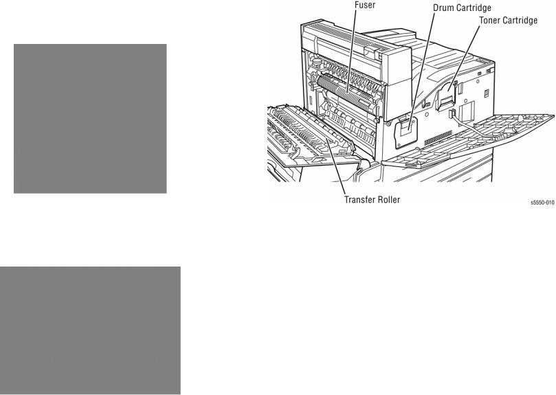
Figure 1 Phaser 5500/5550 Printer
Phaser 5500/5550 Differences
New for the 5550 model is a revised Image Processor Board that increases RAM memory capacity, processor speed, and is redesigned to permit customer replacement. Added to the Rear Panel is an Engine Test Print button that bypasses Image Processor Board logic to quickly isolate some printer malfunctions. Access to error reports is improved with the addition of a Printer Status page that lists the last 30 errors recorded.
The adoption of current controller functionality puts 5550 behavior into alignment with other recently released products. The 5550 offers the same input and output options as the 5500. Supplies and consumables are compatible between models.
Phaser 5500/5550 Printer Configurations
Table 1 lists Phaser 5500/5550 printer configurations.
NOTE: For the 5550 model, base memory is increased from 128 MB to 256MB, with a new maximum of 1 GB. The DX model has been dropped for the 5550.
Table 1 Phaser 5500/5550 Configurations
|
|
|
Printer Configurations 5500/5550 |
|
||
|
|
|
|
|
|
|
Features |
B |
N |
DN |
DT |
DX (5500) |
|
|
|
|
|
|
|
|
Maximum Print |
50 ppm |
50 ppm |
50 ppm |
50 ppm |
50 ppm |
|
Speed (Letter-size |
|
|
|
|
|
|
Paper) |
|
|
|
|
|
|
|
|
|
|
|
|
|
Memory |
128/256 MB |
128/256 MB |
128/256 MB |
128/256 MB |
128 MB |
|
|
|
|
|
|
|
|
PostScript Fonts |
137 |
137 |
137 |
137 |
137 |
|
|
|
|
|
|
|
|
Oak PCL 5.0 |
Yes |
Yes |
Yes |
Yes |
Yes |
|
|
|
|
|
|
|
|
PCL5e/PCL6 |
Yes |
Yes |
Yes |
Yes |
Yes |
|
|
|
|
|
|
|
|
Job Pipelining |
Yes |
Yes |
Yes |
Yes |
Yes |
|
|
|
|
|
|
|
|
PDF Direct Print |
Yes |
Yes |
Yes |
Yes |
Yes |
|
|
|
|
|
|
|
|
Resolutions (dpi) |
600 or True |
600 or True |
600 or True |
600 or True |
600 or True |
|
|
|
1200 dpi |
1200 dpi |
1200 dpi |
1200 dpi |
1200 dpi |
|
|
|
|
|
|
|
USB, Parallel |
Yes |
Yes |
Yes |
Yes |
Yes |
|
|
|
|
|
|
|
|
Ethernet Capabilities |
Optional |
Standard |
Standard |
Standard |
Standard |
|
|
|
|
|
|
|
|
1000-Sheet Feeder |
Optional |
Optional |
Optional |
Standard |
Standard |
|
|
|
|
|
|
|
|
Automatic 2-Sided |
Optional |
Optional |
Standard |
Standard |
Standard |
|
Printing (Requires |
|
|
|
|
|
|
Duplex Unit) |
|
|
|
|
|
|
|
|
|
|
|
|
|
Hard Drive |
Optional |
Optional |
Optional |
Optional |
Standard |
|
|
|
|
|
|
|
|
Job Collation (Hard |
Optional |
Optional |
Optional |
Optional |
Standard |
|
Drive Required) |
|
|
|
|
|
|
|
|
|
|
|
|
|
Proof Print, Personal |
Optional |
Optional |
Optional |
Optional |
Standard |
|
Print, Secure Print, |
|
|
|
|
|
|
Saved Jobs (Hard |
|
|
|
|
|
|
Drive Required) |
|
|
|
|
|
|
|
|
|
|
|
|
|
2,000-Sheet Feeder |
Optional |
Optional |
Optional |
Optional |
Standard |
|
(Requires 1000- |
|
|
|
|
|
|
Sheet Feeder) |
|
|
|
|
|
|
|
|
|
|
|
|
|
3,500-Sheet Feeder |
Optional |
Optional |
Optional |
Optional |
Standard |
|
(Requires 1000- |
|
|
|
|
|
|
Sheet Feeder) |
|
|
|
|
|
|
|
|
|
|
|
|
|
Introduction |
March 2008 |
Initial Issue |
Phaser 5500/5550 Printer Overview, Phaser 5500/ |
|
|
xiv |
Phaser® 5500/5550 Printer |

Parts of the Printer
Front View
1.Standard Output Tray
2.Front Door
3.Trays 2 and 3
4.Optional Duplex Unit
5.Tray 1/MPT
6.2000-Sheet Feeder (Tray 6)
7.1000-Sheet Feeder (Trays 4 & 5)
8.Finisher
9.Stacker Lower Tray
10.Stacker Upper Tray
Figure 1 Front View
Rear View
1.Parallel Connection
2.Test Print Button
3.USB Connection
4.Ethernet Connection
5.Mode Select Port
6.Serial Debug Port
7.Configuration Card
8.Ground Fault Interrupt Reset
9.Printer Power Connection
10.Finisher Connection
11.1000-Sheet Feeder Connection
12.Duplex Unit Connector
Figure 2 Rear View
Initial Issue |
March 2008 |
Introduction |
|
Parts of the Printer |
|
Phaser® 5500/5550 Printer |
xv |

Control Panel
The Control Panel consists of one tricolor LED, a display, and six functional buttons. Listed below are the functions of each Control Panel control and indicator.
1.LED
2.Control Panel Display
3.Toner Gauge
4.Cancel button
5.Back button
6.Up Arrow button - scrolls up the menu system
7.Down Arrow button - scrolls down the menu system
8.OK (select) button
9.Information button - for additional explanation or help
|
Figure 3 Control Panel |
LED States |
|
|
Table 1 LED States |
|
|
LED State |
Print State |
|
|
Green |
Ready to print |
|
|
Flashing Yellow |
Warning (but can still print) |
|
|
Flashing Green |
In Power Saver mode or busy (receiving or processing data) |
|
|
Flashing Red |
Error; cannot print |
|
|
Printer Options
Phaser 5500/5550 printer options include:
•Hard Drive
•Additional RAM and NVRAM
•Exit 2
•1000-Sheet Feeder (Trays 4 & 5)
•Duplex Unit
•3,500-Sheet Stacker (with offset)
•3,500-Sheet Finisher (with hole punch, staple, offset)
•2,000-Sheet Feeder (Tray 6)
•Envelope Tray (replaces Tray 2)
Hard Drive
A hard drive is available to enable the Job Collation, Saved Jobs, Proof, Personal, and Secure Print options. The hard drive installs on the Image Processor Board with stand-offs and connects to the board with a single data/power connector.
Additional Memory
Options provide additional RAM in 256 MB and 512 MB increments. Also available is 32 MB of Flash Memory for fonts, forms, and macros. Both RAM and NVRAM options install to the Image Processing board. The Startup Page and Configuration Page list the amount of installed RAM. Refer to Memory Specifications.
Exit 2
Exit 2 is required when either the Duplex Unit or Stacker/Finisher is installed. When used in conjunction with the Duplex Unit, Exit 2 performs as a paper inverter. With the Stacker/Finisher, Exit 2 serves as the replacement face-down exit to the top tray. Exit 2 mounts directly above Exit 1 with spring loaded latches and guide pins.
Networking
A Configuration Card is used to enable or disable networking capabilities. This option provides a replacement card to enable Ethernet on the base model (Phaser 5500/5550B printer).
Introduction |
March 2008 |
Initial Issue |
Parts of the Printer, Printer Options |
|
|
xvi |
Phaser® 5500/5550 Printer |

1000-Sheet Feeder
The 1000-Sheet Feeder forms a base for the printer and adds two, 500-sheet trays (Tray 4 and Tray 5). Control signals reach the sheet feeder by a single connection. The sheet feeder is secured to the print engine with two screws located under the front edge of Tray 3.
Figure 1 1000-Sheet Feeder
Duplex Unit
The Duplex Unit adds two-sided printing. The Duplex Unit attaches to the left side above Tray 1 using two twist locks. Installation of the Duplex Unit requires that the Exit 2 Module also be added to provide reverse drive. Electrical connection to the printer is made by an interface cable.
Figure 2 Duplex Unit
Stacker / Finisher
The Stacker/Finisher increases the output capacity of the printer by 3,500 sheets. Printer output is directed to the Stacker/Finisher by way of Exit 1 and the Horizontal Transport. With Exit 2 installed, the top surface of the Horizontal Transport serves as the top tray and paper output capacity remains at 500 sheets. Depending on the level of Stacker/Finisher options and job specifications, as paper enters the Stacker/Finisher it is punched, stapled, offset and stacked. Control signals reach the Stacker/Finisher through a single connector. Power is supplied from the printer’s AC Accessory Panel.
Figure 3 Stacker / Finisher
Initial Issue |
March 2008 |
Introduction |
|
Printer Options |
|
Phaser® 5500/5550 Printer |
xvii |
2000-Sheet Feeder |
Consumables and Routine Maintenance Items |
The 2000-Sheet Feeder (Tray 6) nearly doubles the input capacity of the printer. The feeder attaches to the left side of printers equipped with the 1000-Sheet Feeder option just below Tray 1/MPT using the supplied docking bracket. Electrical connection to the printer is made by an interface cable.
Figure 4 2000-Sheet Feeder
Figure 1 Consumables and Routine Maintenance Items
Envelope Tray
The Envelope Tray replaces Tray 2 to feed envelopes.
Supply Life Counters
Counters track the usage of the consumables and routine maintenance items and store the values in NVRAM. Access the current status of these counters from the Supplies Info menu. In addition to the counters, a Toner Gauge is provided on the Control Panel that approximates the Toner Cartridge counter value. As counters near their minimums, warning messages appear on the Control Panel.
Print life ratings are based on 5% average coverage and an average job length of 6 pages.
Table 1 Consumables and Routine Maintenance Items Life Expectancy
|
|
Consumables |
Print Life (Number of Images) |
|
|
|
|
|
|
|
|
Toner Cartridge |
30,000 (5500) 35,000 (5550) |
|
|
|
|
|
|
|
|
Routine Maintenance Items |
|
|
|
|
|
|
|
|
|
Fuser |
300,000 |
|
|
|
|
|
|
|
|
Drum Cartridge |
Up to 60,000 dependent on job size |
|
|
|
|
|
|
|
|
Maintenance Kit (consists of Fuser, |
300,000 |
|
Figure 5 Envelope Tray |
|
Transfer Roller and 15 Feed Rollers) |
|
|
|
|
|
|
|
|
|
|
|
|
CAUTION |
|
|
|
|
To avoid damage to the Enveloper Tray, insert in the Tray 2 position only. |
|
|
|
|
|
|
|
|
|
Introduction |
March 2008 |
|
Initial Issue |
|
Printer Options, Consumables and Routine Mainte- |
|
|
||
xviii |
Phaser® 5500/5550 Printer |
|||

Printer Specifications
Physical Dimensions
Table 1 Physical Dimensions
Device |
Height |
Width |
Depth |
Weight |
|
|
|
|
|
Print Engine |
498 mm (19.6 in.) |
640 mm (25.2 in.) |
525 mm (20.7 in.) |
41 kg 90 lbs.) |
|
|
|
|
|
Duplex Unit |
211 mm (8.3 in.) |
64 mm (2.52 in.) |
458 mm (18.0 in.) |
1.8 kg (4 lbs.) |
|
|
|
|
|
1000-Sheet |
280 mm (11.0 in.) |
540 mm (21.2 in.) |
520 mm (21.1 in.) |
23 kg (50 lbs.) |
Feeder |
|
|
|
|
|
|
|
|
|
Stacker / Fin- |
1050 mm (41.3 in.) |
740 mm (29.1 in.) |
650 mm (25.6 in.) |
49 kg (108 lbs.) |
isher |
|
|
|
|
|
|
|
|
|
Exit 2 |
142 mm (5.6 in.) |
130 mm (5.1 in.) |
460 mm (18.1 in.) |
2 kg (4.4 lbs.) |
|
|
|
|
|
Envelope Tray |
76 mm (3.0 in.) |
538 mm (21.2 in.) |
521 mm (20.5 in.) |
3.2 kg (7 lbs.) |
|
|
|
|
|
2000-Sheet |
363 mm (14.3 in.) |
385.5 mm (15.1 in.) |
600 mm (23.6 in.) |
50 kg (110 lbs.) |
Feeder |
|
|
|
|
|
|
|
|
|
Memory Specifications
|
Table 2 Memory Specifications |
Characteristic |
Specification |
|
|
Minimum RAM |
128 MB (5500), 256 MB (5550) |
|
|
Maximum RAM |
512 MB (5500), 1 GB (5550) |
|
|
Supported RAM |
SO-DIMM 144-pin module of 128, 256, or 512 MB. All combina- |
|
tions are allowed for configurations to the maximum allowable. |
|
|
NVRAM |
Single chip either PPROM or StrataFlash 16 or 32 MB |
|
|
Initial Issue |
March 2008 |
Introduction |
|
Printer Specifications |
|
Phaser® 5500/5550 Printer |
xix |
Functional Specifications
|
Table 3 Functional Specifications |
|
Characteristic |
Specification |
|
|
|
|
Printing Process |
Recording System: Electrophotography (roller charging, mag- |
|
|
netic dual component toner and DRUM Cartridge) |
|
|
Exposure System: Semiconductor laser beam scanning |
|
|
Transfer System: Roller transfer system |
|
|
Fusing System: Thermal fixing using a heat roller |
|
|
|
|
Resolution / Addressability |
600/ True 1200 dpi |
|
|
|
|
Print-Quality Modes |
Two choices: |
|
|
• |
600 x 600 dpi |
|
• |
True 1200 x 1200 dpi |
|
|
|
Continuous Operating |
50 pages per minute for plain Letter paper, simplex or duplex |
|
Printing Speed |
50 pages per minute for A4 paper, simplex or duplex |
|
|
|
|
Warm-Up Time: |
|
|
Sleep Mode |
45 sec. |
|
Stand By |
6 sec. |
|
|
|
|
Electrical Specifications
|
Table 4 Electrical Specifications |
Characteristic |
Specification |
|
|
Primary Line Voltages |
120 VAC nominal, min. 99 V, max. 135 V |
|
220/240 VAC nominal, min. 198 V, max. 254 V |
|
|
Primary Line Voltage Fre- |
50/60 Hz +/-3 Hz |
quency Range |
|
|
|
Input Current: |
|
Operating |
12 A max. @ 120 V |
|
8 A max. @ 240 V |
Rush |
100 A max. |
|
|
Power Consumption: |
|
Operating (5500/5550DX) |
1150 W max. @ 120 V, 1300 W max. @ 240 V |
Sleep Mode |
10 W max @ 120/240 V |
BTU’s at 120V: |
Operating 3924 |
|
Power Saver 34 |
BTU’s at 240V: |
Operating 4436 |
|
Power Saver 34 |
|
|
Environmental Specifications
Table 5 Environmental Specifications |
|
|||
Characteristic |
|
Specification |
|
|
|
|
|
|
|
Temperature |
|
|
|
|
Operating |
|
5 to 32° C (41 to 95° F) |
|
|
Transportation |
|
-20 to 40° C (-4 to 104° F) |
||
|
|
|
|
|
Humidity (%RH) |
|
|
|
|
Operating |
|
15 to 85 |
|
|
Transportation |
|
5 to 85 |
|
|
|
|
|
|
|
Altitude |
|
|
|
|
Operating |
|
0 to 2,500 meters (8,200 feet) |
||
Transportation* |
|
0 to 15,000 meters (49,200 feet) |
||
|
|
|
|
|
Print Engine Acoustic Noise LWA(B) |
|
Engine Only |
|
Bystander Position |
Standby |
|
4.0 B |
|
22 db |
Printing |
|
7.1 B |
|
54 db |
|
|
|
|
|
Options Acoustic Noise LWA(B) |
|
Engine Only |
|
With Options |
Idle |
|
4.00 B |
|
--- |
Printing |
|
6.80 B |
|
7.00 B |
|
|
|
|
|
* Air transportation in pressurized cargo space |
|
|
|
|
|
|
|
|
|
Tray and Media Specifications |
|
|
|
|
Table 6 Tray Specifications
Characteristic |
Trays |
Specification |
|
|
|
|
|
Printable Area |
All |
Within 4 mm of paper edge guaranteed. Edge- |
|
|
|
to-edge printing supported. |
|
|
|
|
|
Supported Enve- |
Tray 1 or Tray 2 (with |
COM-10 (4.1 x 9.5 in.) |
|
lopes |
Envelope Tray installed) |
Monarch (3.8 x 7.5 in.) |
|
|
|
DL (110 x 220 mm) |
|
|
|
C5 (162 x 229 mm) |
|
|
|
|
|
Supported |
Tray 1,3,4,5,6 |
60-216 g/m2 (16 lb. bond to 133 lb. card stock) |
|
Media Weights |
Tray 2 |
60-105 g/m2 (16 to 28 lb. bond) |
|
|
Duplex |
60-163 g/m2 |
|
|
|
||
Tray Capacity |
Tray 1 |
100 |
Sheets / 15 envelopes |
|
Tray 2 |
500 |
Sheets or to fill line with Envelope Tray |
|
Tray 3 |
500 |
Sheets |
|
Tray 4 |
500 |
Sheets |
|
Tray 5 |
500 |
Sheets |
|
Tray 6 |
2000 Sheets |
|
|
Top (face-down) |
500 |
Sheets |
|
Stacker/Finisher |
3000 elevator, 500 in top tray |
|
|
|
Based on 75 g/m2 (20 lb. letter-size) paper. |
|
|
|
Capacity is reduced for heavier/thicker stock. |
|
|
|
|
|
Introduction |
March 2008 |
Initial Issue |
Printer Specifications |
|
|
xx |
Phaser® 5500/5550 Printer |

Phaser 5500/5550 Printer Menu Map
Figure 1 Menu Map (page 1)
Figure 2 Menu Map (page 2)
Initial Issue |
March 2008 |
Introduction |
|
Phaser 5500/5550 Printer Menu Map |
|
Phaser® 5500/5550 Printer |
xxi |

1 Service Call Procedures
Service Call Procedures.................................................................................................. |
1-3 |
Servicing Instructions ...................................................................................................... |
1-4 |
Initial Issue |
March 2008 |
Service Call Procedures |
|
|
|
Phaser® 5500/5550 Printer |
1-1 |
|

Service Call Procedures
Perform the following procedures whenever you check, service, or repair a printer. Cleaning the printer, as outlined in the following steps, assures proper operation of the printer and reduces the probability of having to service the printer in the future.
The frequency of use and the type of paper a customer prints on determines how critical and how often cleaning is necessary.
Technician’s Tool Kit
Table 1 lists rcommon tools used to service this and other similar products.
Table 1 Service Tools
Description |
Detail |
Part Number |
|
|
|
Phillips Drivers |
#2 and #1 5.0 x 75mm, 3.0 x 75mm, 6.0 x |
|
|
100mm |
|
|
|
|
Screw Driver |
(-) 3 x 50 |
600T40205 |
|
|
|
Screw Driver |
(+) 6 x 100 |
600T1989 |
|
|
|
Screw Driver |
(+) NO. 1 |
499T356 |
|
|
|
Screw Driver |
(=) 100MM |
499T355 |
|
|
|
Spanner and Wrench |
5.5 x 5.5 |
600T40501 |
|
|
|
Spanner and Wrench |
7 x 7 |
600T40502 |
|
|
|
Hex Key Set |
|
600T02002 |
|
|
|
Box Driver |
5.5 mm |
600T1988 |
|
|
|
Box Driver |
1/4 inch |
|
|
|
|
Side Cutting Nipper |
|
600T40903 |
|
|
|
Round Nose Pliers |
|
600T40901 |
|
|
|
Lubricant/Grease |
Reolube |
070E00890 |
|
|
|
Cleaners |
Multipurpose surface cleaner and Alcohol |
|
|
|
|
ESD Strap |
|
|
|
|
|
Nut Driver |
5.5mm (magnetic) |
600T2123 |
|
|
|
Serial Adaptor Cable |
|
600T80374 |
|
|
|
Network Cross-over cable |
Tech |
|
|
|
|
Multimeter |
Volts, Ohms, Current |
600T2020 |
|
|
|
Interlock Cheater |
|
600T91616 |
|
|
|
Silver Scale |
150MM |
600T41503 |
|
|
|
CE Tool Case |
|
600T1901 |
|
|
|
Magnetic Screw Pick-up |
|
600T41911 |
|
|
|
Scribe Tool |
|
600T41913 |
|
|
|
Eye Loop |
|
600T42008 |
|
|
|
Flashlight |
|
600T1824 |
|
|
|
Brush |
|
600T41901 |
|
|
|
Test Lead Red |
|
600T9583 |
|
|
|
Test Lead Black |
|
600T2030 |
|
|
|
IC Chip Puller |
|
|
|
|
|
Cleaning
CAUTION
Never apply alcohol to any parts in the printer. If you remove the Drum Cartridge, place it in a light protective bag.
NOTE: Never use a damp cloth to clean up toner.
1.Record number of sheets printed.
2.Print several sheets of paper to check for problems or defects. Print to all output trays and staple or punch if Finisher is installed.
3.Print the fault history. Diagnose and repair to correct listed faults.
4.Turn Off the printer and disconnect the Power Cord.
5.Remove the I/P Board and Upper Rear covers and clean the Fuser Fan with a brush or dry cloth to remove excess dust and toner.
6.Remove any debris or foreign objects from the Transfer Roller, Fuser, Laser Assembly, and paper path.
7.Vacuum out any loose toner with a Type II toner vacuum only.
8.Remove and clean all paper trays.
9.Clean feed rollers with a lint-free cloth lightly dampened with water.
10.Inspect the interior of the printer for damaged wires, loose connections, toner leakage, and damaged or obviously worn parts.
11.If the Drum or Toner Cartridges appear damaged, replace with a new one.
Initial Issue |
March 2008 |
Service Call Procedures |
|
Service Call Procedures |
|
Phaser® 5500/5550 Printer |
1-3 |
Servicing Instructions
These instructions are an overview of the Steps a service technician should take, using this manual, to service the print engine and options. If you choose not to use these Steps, it is recommended that you start at the appropriate troubleshooting procedure and proceed from there. When servicing the printer, always follow the safety measures detailed in Service Safety Summary in Introduction section.
Table 1 Servicing Instructions
Description
Step 1: Identify the Problem
•Verify the reported problem does not exist.
•Check for any error codes and write them down.
•Print normal customer prints and service test prints.
•Make note of any print-quality problems in the test prints.
•Make note of any mechanical or electrical abnormalities present.
•Make note of any unusual noise or smell coming from the printer.
•Print a Service Usage Profile, if the printer is able to print.
•View the Engine Error and Jam Histories under the Service Tools menu.
•Verify the AC input from the wall outlet is within specifications.
Step 2: Inspect and Clean the Printer
•Follow the Cleaning instructions in section 1, Service Call Procedures.
•Verify that the power cord is in serviceable condition.
•Restart the printer to check if the error reoccurs.
Step 3: Find the Cause of the Problem
•Use the troubleshooting procedures to find the root cause of the problem.
•Use Service Diagnostics to check the printer and optional components.
•Use the Wiring Diagrams and Plug/Jack Locator to locate test points.
•Take voltage readings as instructed in the appropriate troubleshooting procedure.
Step 4: Correct the Problem
•Use the Parts List to locate a part number.
•Use the FRU Disassembly procedures to replace the part.
Step 5: Final Checkout
•Test the printer to verify the problem is corrected and no new problems arose.
Service Call Procedures |
March 2008 |
|
Servicing Instructions |
||
1-4 |
Initial Issue
Phaser® 5500/5550 Printer

|
|
.........................................................................................................................Overview |
2-3 |
Messages, Codes, and Procedures
Entry Level Fault Isolation Procedure ............................................................................. |
2-9 |
Main Motor Failure .......................................................................................................... |
2-9 |
Drum Motor Failure - U1-4 Drum Motor Failure .............................................................. |
2-10 |
Laser Unit Failure - U3-3 Laser Power............................................................................ |
2-10 |
Laser Motor Failure - U3-5 Polygon Motor Rotation ....................................................... |
2-11 |
Fuser Failure - U4-1 On Time ......................................................................................... |
2-11 |
Fuser Failure - U4-n Over Heat / Thermistor .................................................................. |
2-12 |
Fuser Failure - U4-7 Cold Sagging ................................................................................. |
2-13 |
Fan Failure - U4-9 Fan Defect ........................................................................................ |
2-14 |
Toner Motor Failure - U5-1 Motor Rotation ..................................................................... |
2-14 |
Fan Failure - U5-9 Fan Failure........................................................................................ |
2-15 |
Engine Control Board Failure - U6-2, 3, 4, 5, 6, 7........................................................... |
2-15 |
Paper Size Jam - E1-1 Regi Area Jam ........................................................................... |
2-16 |
Jam at A - E1-2 Regi Area Jam ...................................................................................... |
2-17 |
Jam at A - E1-6 Regi Area Jam ...................................................................................... |
2-18 |
Jam at A - Fuser Area Jam ............................................................................................. |
2-18 |
Jam at A - E3-6 Fuser Area Jam..................................................................................... |
2-19 |
Jam at A - E4-1 Exit 2 Area Jam..................................................................................... |
2-20 |
Jam at E - E4-3 Exit 2 Area Jam..................................................................................... |
2-21 |
Jam at E - E4-6 Exit 2 Area Jam..................................................................................... |
2-23 |
Jam at E - E8-2 Duplex Area Jam................................................................................... |
2-24 |
Jam at D and A - C6-1 Duplex Area Jam........................................................................ |
2-25 |
Jam at D and A - C6-2 Duplex Area Jam........................................................................ |
2-26 |
Jam at Tray n - Pre-Feed ................................................................................................ |
2-28 |
Jam at Tray n - Registration............................................................................................ |
2-29 |
Jam at Tray n - Feed Out #3 ........................................................................................... |
2-30 |
Jam at Tray n - Feed Out #4 ........................................................................................... |
2-31 |
Jam at Tray 5 - C4-0 Tray 5 ............................................................................................ |
2-32 |
Jam at Tray 6 - C5-1 Tray 6 ............................................................................................ |
2-33 |
Jam at Tray 6 - C5-2 Tray 6 ............................................................................................ |
2-35 |
Jam at B - C5-3 Tray 6.................................................................................................... |
2-37 |
Jam at B - C8-2 F/03 SNR Static Jam ............................................................................ |
2-38 |
Jam at C - C8-3 F/04 SNR Static Jam ............................................................................ |
2-39 |
Jam at C - C8-4 F/05 SNR Static Jam ............................................................................ |
2-39 |
Jam at Tray 6 - C8-5 HCF F/0 Sensor Static Jam .......................................................... |
2-40 |
Jam at D - C8-6 Duplex................................................................................................... |
2-42 |
Jam at Tray 1/MPT - C9-3 Tray 1/MPT........................................................................... |
2-42 |
Jam at A - F4-12 H-Transport Entrance Sensor ON ....................................................... |
2-43 |
Jam at A or F - F4-n H-Transport Entrance Sensor Static .............................................. |
2-45 |
Jam at A or F - F4-n H-Transport Exit Sensor ON .......................................................... |
2-46 |
Jam at F - F4-26 H-Transport Exit Sensor Static ............................................................ |
2-47 |
Jam at F - F4-32 Transport Entrance Sensor ON ........................................................... |
2-48 |
Jam at F - F4-36 Transport Entrance Sensor Static ....................................................... |
2-50 |
Jam at G - F4-4n Buffer Path Sensor ON ....................................................................... |
2-51 |
Jam at G - F4-4n Buffer Path Sensor Static.................................................................... |
2-54 |
2 Status Indicator RAPs
Jam at F or H - F4-5n Compile Exit Sensor OFF ............................................................ |
2-56 |
Jam at F or G - F4-5n Compile Exit Sensor ON.............................................................. |
2-57 |
Jam at H - F4-56 Compile Exit Sensor Static.................................................................. |
2-59 |
Jam at H - F4-61 Set Eject Jam ...................................................................................... |
2-61 |
Jam at H - F4-66 Compile Paper Sensor Static .............................................................. |
2-62 |
Jam at F or G - F4-7n Top Tray Exit Sensor ON............................................................. |
2-64 |
Jam at F or Stacker Upper Tray - F4-7n Top Tray Sensor OFF ..................................... |
2-65 |
Jam at F or G - F4-7n Top Tray Exit Sensor Static ......................................................... |
2-67 |
Jam at F - F4-82 Gate Sensor ON .................................................................................. |
2-68 |
Jam at F or G - Gate Sensor Static Jam (Upper Tray).................................................... |
2-70 |
Jam at F or G - Gate Sensor Static Jam (Lower Tray).................................................... |
2-72 |
Tray n Failure - H1 -1/2/3/4 Tray n Fail ........................................................................... |
2-73 |
Tray 6 Failure - H1-5 Tray 6 Fail ..................................................................................... |
2-75 |
Duplex Unit Failure - H2-7 Duplex Comm Failure ........................................................... |
2-77 |
Incorrect Duplex Unit Installed - H2-8 Duplex Type Error ............................................... |
2-78 |
Exit Unit Failure - H3-n Offset Error ................................................................................ |
2-78 |
Exit Unit Failure - H3-7 Exit Board Comm Failure........................................................... |
2-80 |
Tray 1/MPT Paper Guide Does Not Match Size Menu.................................................... |
2-81 |
Tray Paper Guide Does Not Match Size Menu -H4-1/2 .................................................. |
2-81 |
Tray Paper Guide Does Not Match Size Menu -H4-3/4 .................................................. |
2-82 |
Finisher Board Failure - H5-4, 7, 8 NVM/Comm/Type Error ........................................... |
2-84 |
Stacker Lower Tray Failure - H5-11 Low Tray Fail.......................................................... |
2-85 |
Stacker Lower Tray Failure - H5-12 Low Tray Upper Limit ............................................. |
2-86 |
Stacker Lower Tray Failure - H5-13 Lower Tray Limit..................................................... |
2-87 |
Stacker Lower Tray Failure - H5-2n Front Home Sensor................................................ |
2-89 |
Stacker Lower Tray Failure - H5-2n Rear Home Sensor ................................................ |
2-91 |
Punch Failure - H5-3n Sensor......................................................................................... |
2-92 |
Punch Failure - H5-3n Home Sensor .............................................................................. |
2-93 |
Stacker Lower Tray Failure - H5-8n Eject Clamp Sensor ............................................... |
2-94 |
Stacker Lower Tray Failure - H5-8n Set Clamp Sensor .................................................. |
2-95 |
Stacker Lower Tray Failure - H5-86 Side Regi Sensor OFF ........................................... |
2-97 |
Stapler Failure - H5-91 Staple Fail .................................................................................. |
2-99 |
Stapler Failure - H5-9n Move Sensor.............................................................................. |
2-100 |
Tray 6 Control Board Failure - H6-4 NVM R/W Error ...................................................... |
2-101 |
Tray 6 Control Board Failure - H6-7 HFC Comm Failure ................................................ |
2-101 |
Tray 4-5 Control Board Failure - NVM............................................................................. |
2-102 |
Tray 4-5 Control Board Failure - H7-7 Comm Failure ..................................................... |
2-103 |
Incorrect Tray 4-5 Installed - H7-8 Type Error................................................................. |
2-104 |
Tray N Failure - H8-1, Tray 2-3 Size Sensor Broken ...................................................... |
2-105 |
Tray N Failure - H8-3, 4-5 Tray Size Sensor Broken ...................................................... |
2-106 |
Toner Empty - J1-2 Toner Empty ................................................................................... |
2-107 |
No Drum Cartridge - J3-1 Drum Not Installed ................................................................ |
2-108 |
Drum Cartridge Failure - J4-1 ATC Sensor Detect.......................................................... |
2-109 |
Replace Drum Cartridge - J6-1 Drum End of Life .......................................................... |
2-109 |
Drum Cartridge Failure - J7-n Comm/NVRAM/Type Error ............................................. |
2-110 |
Replace Incorrect Drum Cartridge - J7-3 DRUM Type Mismatch .................................. |
2-110 |
Toner Cartridge Failure - J8-n Toner Comm/Read/Write ............................................... |
2-111 |
Replace Incorrect Toner Cartridge - J8-3 Toner Cartridge Type Mismatch ................... |
2-111 |
Initial Issue |
March 2008 |
Status Indicator RAPs |
|
|
|
Phaser® 5500/5550 Printer |
2-1 |
|

Toner Is Low - Toner Low ............................................................................................... |
2-112 |
Drum Cartridge Near End of Life - DRUM Life Near End................................................ |
2-113 |
Tray Empty - No Paper in Tray 2 or 3 ............................................................................. |
2-114 |
Tray Empty - No Paper in Tray 4 or 5 ............................................................................. |
2-115 |
Tray Empty - No Paper in Tray 6 .................................................................................... |
2-116 |
Paper Size Jam - Paper Size in Tray 2 or 3.................................................................... |
2-117 |
Paper Size Jam - Paper Size in Tray 4 or 5.................................................................... |
2-118 |
Paper Size Jam - Paper Size in Tray 6 ........................................................................... |
2-120 |
Drum Cartridge Failure - Drum ATC Value Out of Range............................................... |
2-121 |
Temp/Humidity Sensor Failure - Value Out of Range..................................................... |
2-121 |
Face Down Tray Paper Full - Face Down Tray Full ........................................................ |
2-122 |
Stacker Upper Tray Full - Finisher Tray Paper Full......................................................... |
2-123 |
Stacker Lower Tray Full - Finisher Mix Full Stack........................................................... |
2-124 |
Stapler is Empty - Staple Pin Warning ............................................................................ |
2-125 |
Staple Cartridge is Low or Missing - Staple Pin Misfeed ................................................ |
2-126 |
Stapler Failure - Staple Failure ....................................................................................... |
2-127 |
Staple Set Over Count .................................................................................................... |
2-128 |
Stacker Lower Tray Failure ............................................................................................. |
2-128 |
Punch Waste Box is Missing........................................................................................... |
2-129 |
Punch Waste Box is Full ................................................................................................. |
2-130 |
Printer Front Door is Open - Front Cover is Open .......................................................... |
2-131 |
Slide In Tray 6 Feeder - Tray 6 Undocked ...................................................................... |
2-132 |
Close Door A - Door A is Open ....................................................................................... |
2-133 |
Close Door B - Door B is Open ....................................................................................... |
2-133 |
Close Door C - Door C is Open....................................................................................... |
2-134 |
Close Door D - Door D is Open....................................................................................... |
2-135 |
Close Door E - Door E is Open ....................................................................................... |
2-136 |
Close Door F - Door F is Open ....................................................................................... |
2-136 |
Close Door G - Door G is Open ...................................................................................... |
2-137 |
Close Door H - Door H is Open....................................................................................... |
2-138 |
Close Door J - Door J is Open ........................................................................................ |
2-139 |
Replace Maintenance Kit ................................................................................................ |
2-140 |
Invalid or Missing Configuration Card ............................................................................. |
2-141 |
Duplicate IP Address Detected ....................................................................................... |
2-141 |
Status Indicator RAPs |
March 2008 |
|
|
|
2-2 |
Initial Issue
Phaser® 5500/5550 Printer

Overview
This chapter describes the printer’s self-diagnostic capabilities and includes methods to identify and remedy reported printer problems. The diagnostic routines report problems using error messages and fault codes displayed on the Front Panel, logged in the Service Usage Profile, listed on the Startup Page or by flashing LEDs. These error indications serve as the entry point into the troubleshooting process. Printer problems not directly indicated by or associated with an error message or fault code are covered in Section 6, “General Troubleshooting.” Printquality problems are covered in Section 3, “Image Quality.”
Introduction
The error messages and codes generated by the printer’s operating system, the Service Usage Profile, and Service Diagnostics are the lead-in to the troubleshooting procedures that follow in subsequent pages. This section correlates the output of these three diagnostic aids and provides the troubleshooting procedure to locate and correct reported errors.
Error Message Abbreviations
Due to limited display space, some error messages include abbreviations. The most common abbreviations used throughout this section are listed here.
Table 1 Error Message Abbreviations
Term |
Definition |
Comment |
|
|
|
Reg or REGI |
Registration |
Used in designators such as Reg SNR. |
|
|
|
SNR |
Sensor |
Often seen as SNR1 or Reg SNR. |
|
|
|
DUP or DM |
Duplex Unit |
Optional for 2-sided printing. |
|
|
|
F/O |
Feed Out |
Used as sensor designators F/O3 or F/O #4. |
|
|
|
T/A |
Take Away |
Function designator for roller or motor. |
|
|
|
H-Xport |
Horizontal Transport |
Horizontal Transport section of the Finisher. |
|
|
|
MCU |
Main Control Unit |
Engine Control Board |
|
|
|
I/P Board |
Image Processor |
Image Processor Board |
|
|
|
OCT |
Offset Catch Tray |
Offset Rollers at Exit |
|
|
|
HCF |
High-Capacity Feeder |
Option Tray 6 or 2000-Sheet Feeder |
|
|
|
MSI or MPT |
Multi-Sheet Input |
Used to describe Tray 1/MPT. |
|
|
|
IOT |
Image Output Terminal |
Used instead of printer. |
|
|
|
2TM |
Two-tray Module |
Option Trays 4 and 5 or 1000-Sheet Feeder |
|
|
|
P/J |
Plug/Jack |
Plug (P) and or Jack (J) designators |
|
|
|
EM |
Exit Module |
Used for either Exit (1 or optional Exit 2). |
|
|
|
SW |
Switch |
Appears as a designator. |
|
|
|
NVM |
Non-volatile Memory |
Used instead of NVRAM. |
|
|
|
CRUM |
Customer-Replaceable |
Device used to store usage information on the |
|
Unit Monitor |
Drum and Toner Cartridges. |
|
|
|
Comm |
Communication |
As in MCU-DM Comm Error. |
|
|
|
LVPS |
Low-Voltage Power |
Primary power supply. |
|
Supply |
|
|
|
|
PWB |
Printed Wire Board |
Used to describe a circuit board (Tray 6 PWB). |
|
|
|
Error Message Summary
The Error Message Summary below lists possible error messages, along with, the corresponding Service Diagnostic message and Service Usage Profile fault code. The Control Panel Message column shows the message as is appears on the printer’s display when the error occurs during normal operation. The Service Diagnostics’ error message appears when errors occur during testing. The Engine and Jam Errors columns list fault codes logged by the Service Usage Profile, located in the Service Tools menu. The Go to Page column references the troubleshooting procedure related to the error.
In cases where an error message or fault code is generated, use this table to identify the proper procedure to clear the error. To assist you further, the troubleshooting procedures that follow this table are named for the associated Control Panel message.
Table 2 Error Message Summary
Control Panel |
Service Diagnostics |
Engine |
Jam |
|
Message |
Message |
Error |
Error |
Go to RAP |
|
|
|
|
|
Main Motor Failure |
U0-1 Main Motor Stop |
19 |
|
Main Motor Failure |
|
|
|
|
|
Main Motor Failure |
U1-1 Main Motor Rota- |
19 |
|
Main Motor Failure |
|
tion |
|
|
|
|
|
|
|
|
Drum Motor Failure |
U1-4 Drum Motor Rota- |
20 |
|
Drum Motor Failure - U1-4 |
|
tion |
|
|
Drum Motor Failure |
|
|
|
|
|
Laser Unit Failure |
U3-3 Laser Power |
23 |
|
Laser Unit Failure - U3-3 |
|
|
|
|
Laser Power |
|
|
|
|
|
Laser Motor Failure |
U3-5 Polygon Motor |
22 |
|
Laser Motor Failure - U3-5 |
|
Rotation |
|
|
Polygon Motor Rotation |
|
|
|
|
|
Fuser Failure |
U4-1 On Time |
24 |
|
Fuser Failure - U4-1 On |
|
|
|
|
Time |
|
|
|
|
|
Fuser Failure |
U4-2 Over Heat Temp |
24 |
|
Fuser Failure - U4-n Over |
|
|
|
|
Heat / Thermistor |
|
|
|
|
|
Fuser Failure |
U4-3 FS1 Thermisitor |
24 |
|
Fuser Failure - U4-n Over |
|
|
|
|
Heat / Thermistor |
|
|
|
|
|
Fuser Failure |
U4-4 FS2 Thermisitor |
24 |
|
Fuser Failure - U4-n Over |
|
|
|
|
Heat / Thermistor |
|
|
|
|
|
Fuser Failure |
U4-5 PR Thermisitor |
24 |
|
Fuser Failure - U4-n Over |
|
|
|
|
Heat / Thermistor |
|
|
|
|
|
Fuser Failure |
U4-7 Cold-Sagging |
24 |
|
Fuser Failure - U4-7 Cold |
|
|
|
|
Sagging |
|
|
|
|
|
Fan Failure |
U4-9 Fan Defect |
25 |
|
Fan Failure - U4-9 Fan |
|
|
|
|
Defect |
|
|
|
|
|
Toner Motor Failure |
U5-1 Motor Rotation |
21 |
|
Toner Motor Failure - U5-1 |
|
|
|
|
Motor Rotation |
|
|
|
|
|
Fan Failure |
U5-9 Fan Failure |
25 |
|
Fan Failure - U5-9 Fan Fail- |
|
|
|
|
ure |
|
|
|
|
|
Engine Control |
U6-2 RAM Read/Write |
26 |
|
Engine Control Board Fail- |
Board Failure |
|
|
|
ure - U6-2, 3, 4, 5, 6, 7 |
|
|
|
|
|
Initial Issue |
March 2008 |
Status Indicator RAPs |
|
Overview |
|
Phaser® 5500/5550 Printer |
2-3 |

Table 2 Error Message Summary
Control Panel |
Service Diagnostics |
Engine |
Jam |
|
Message |
Message |
Error |
Error |
Go to RAP |
|
|
|
|
|
Engine Control |
U6-3 NVM Data Defect |
26 |
|
Engine Control Board Fail- |
Board Failure |
|
|
|
ure - U6-2, 3, 4, 5, 6, 7 |
|
|
|
|
|
Engine Control |
U6-4 NVM Read/Write |
26 |
|
Engine Control Board Fail- |
Board Failure |
|
|
|
ure - U6-2, 3, 4, 5, 6, 7 |
|
|
|
|
|
Engine Control |
U6-5 CP/U Power NVM |
26 |
|
Engine Control Board Fail- |
Board Failure |
|
|
|
ure - U6-2, 3, 4, 5, 6, 7 |
|
|
|
|
|
Engine Control |
U6-6 ASIC/CRUM |
26 |
|
Engine Control Board Fail- |
Board Failure |
|
|
|
ure - U6-2, 3, 4, 5, 6, 7 |
|
|
|
|
|
Engine Control |
U6-7 PPM Data |
26 |
|
Engine Control Board Fail- |
Board Failure |
|
|
|
ure - U6-2, 3, 4, 5, 6, 7 |
|
|
|
|
|
Paper Size Jam |
E1-1 Regi Area Jam |
|
18 |
Engine Control Board Fail- |
|
|
|
|
ure - U6-2, 3, 4, 5, 6, 7 |
|
|
|
|
|
Jam at A |
E1-2 Regi Area Jam |
|
7 |
Jam at A - E1-2 Regi Area |
|
|
|
|
Jam |
|
|
|
|
|
Jam at A |
E1-6 Regi Area Jam |
|
7 |
Jam at A - E1-6 Regi Area |
|
|
|
|
Jam |
|
|
|
|
|
Jam at A |
E3-1 Fuser Area Jam |
|
7 |
Jam at A - Fuser Area Jam |
|
|
|
|
|
Jam at A |
E3-2 Fuser Area Jam |
|
7 |
Jam at A - Fuser Area Jam |
|
|
|
|
|
Jam at A |
E3-6 Fuser Area Jam |
|
7 |
Jam at A - E3-6 Fuser Area |
|
|
|
|
Jam |
|
|
|
|
|
Jam at A |
E4-1 Exit 2 Area Jam |
|
7 |
Jam at A - E4-1 Exit 2 Area |
|
|
|
|
Jam |
|
|
|
|
|
Jam at E |
E4-3 Exit 2 Area Jam |
|
11 |
Jam at E - E4-3 Exit 2 Area |
|
|
|
|
Jam |
|
|
|
|
|
Jam at A |
E4-5 Exit 2 Area Jam |
|
7 |
Jam at E - E4-3 Exit 2 Area |
|
|
|
|
Jam |
|
|
|
|
|
Jam at E |
E4-6 Exit 2 Area Jam |
|
11 |
Jam at E - E4-6 Exit 2 Area |
|
|
|
|
Jam |
|
|
|
|
|
Jam at E |
E8-2 Duplex Area Jam |
|
11 |
Jam at E - E8-2 Duplex Area |
|
|
|
|
Jam |
|
|
|
|
|
Jam at Tray 2 |
C1-2 Tray 2 |
|
2 |
Jam at Tray n - Pre-Feed |
|
|
|
|
|
Jam at Tray 2 |
C1-3 Tray 3 |
|
2 |
Jam at Tray n - Registration |
|
|
|
|
|
Jam at Tray 3 |
C2-1 Tray 3 |
|
3 |
Jam at Tray n - Pre-Feed |
|
|
|
|
|
Jam at Tray 3 |
C2-2 Tray 3 |
|
3 |
Jam at Tray n - Feed Out #3 |
|
|
|
|
|
Jam at B |
C2-3 Tray 3 |
|
8 |
Jam at Tray n - Registration |
|
|
|
|
|
Jam at Tray 4 |
C3-0 Tray 4 |
|
4 |
Jam at Tray n - Pre-Feed |
|
|
|
|
|
Jam at Tray 4 |
C3-1 Tray 4 |
|
4 |
Jam at Tray n - Feed Out #4 |
|
|
|
|
|
Jam at B and C |
C3-2 Tray 4 |
|
16 |
Jam at Tray n - Feed Out #3 |
|
|
|
|
|
Jam at B |
C3-3 Tray 4 |
|
8 |
Jam at Tray n - Registration |
|
|
|
|
|
Jam at Tray 5 |
C4-0 Tray 5 |
|
5 |
Jam at Tray 5 - C4-0 Tray 5 |
|
|
|
|
|
Jam at Tray 5 |
C4-1 Tray 5 |
|
5 |
Jam at Tray n - Feed Out #4 |
|
|
|
|
|
Jam at B and C |
C4-2 Tray 5 |
|
16 |
Jam at Tray n - Feed Out #3 |
|
|
|
|
|
Table 2 Error Message Summary
Control Panel |
Service Diagnostics |
Engine |
Jam |
|
Message |
Message |
Error |
Error |
Go to RAP |
|
|
|
|
|
Jam at B |
C4-5 Tray 5 |
|
8 |
Jam at Tray n - Registration |
|
|
|
|
|
Jam at Tray 5 |
C4-4 Tray 5 |
|
5 |
Jam at Tray n - Pre-Feed |
|
|
|
|
|
Jam at Tray 6 |
C5-1 Tray 6 |
|
6 |
Jam at Tray 6 - C5-1 Tray 6 |
|
|
|
|
|
Jam at Tray 6 |
C5-2 Tray 6 |
|
6 |
Jam at Tray 6 - C5-2 Tray 6 |
|
|
|
|
|
Jam at B |
C5-3 Tray 6 |
|
8 |
Jam at B - C5-3 Tray 6 |
|
|
|
|
|
Jam at D and A |
C6-1 Duplex Area Jam |
|
15 |
Jam at D and A - C6-1 |
|
|
|
|
Duplex Area Jam |
|
|
|
|
|
Jam at D and A |
C6-2 Duplex Area Jam |
|
15 |
Jam at D and A - C6-2 |
|
|
|
|
Duplex Area Jam |
|
|
|
|
|
Jam at B |
C8-2 F/O2 SNR Static |
|
8 |
Jam at B - C8-2 F/03 SNR |
|
Jam |
|
|
Static Jam |
|
|
|
|
|
Jam at C |
C8-3 F/O3 SNR Static |
|
9 |
Jam at C - C8-3 F/04 SNR |
|
Jam |
|
|
Static Jam |
|
|
|
|
|
Jam at C |
C8-4 F/O3 SNR Static |
|
9 |
Jam at C - C8-4 F/05 SNR |
|
Jam |
|
|
Static Jam |
|
|
|
|
|
Jam at Tray 6 |
C8-5 HCF F/O SNR |
|
6 |
Jam at Tray 6 - C8-5 HCF F/ |
|
Static Jam |
|
|
0 Sensor Static Jam |
|
|
|
|
|
Jam at D |
C8-6 Duplex |
|
10 |
Jam at D - C8-6 Duplex |
|
|
|
|
|
Jam at Tray 1 (MPT) |
C9-3 Tray 1/MPT |
|
1 |
Jam at Tray 1/MPT - C9-3 |
|
|
|
|
Tray 1/MPT |
|
|
|
|
|
Jam at A |
F4-12 H-Xport Ent SNR |
|
7 |
Jam at A - F4-12 H-Trans- |
|
ON |
|
|
port Entrance Sensor ON |
|
|
|
|
|
Jam at A |
F4-16 H-Xport Ent SNR |
|
7 |
Jam at A or F - F4-n H- |
|
Static Jam A |
|
|
Transport Entrance Sensor |
|
|
|
|
Static |
|
|
|
|
|
Jam at F |
F4-17 H-Xport Ent SNR |
|
12 |
Jam at A or F - F4-n H- |
|
Static Jam B |
|
|
Transport Entrance Sensor |
|
|
|
|
Static |
|
|
|
|
|
Jam at A |
F4-22 H-Xport Exit SNR |
|
7 |
Jam at A or F - F4-n H- |
|
ON Jam A |
|
|
Transport Exit Sensor ON |
|
|
|
|
|
Jam at F |
F4-23 H-Xport Exit SNR |
|
12 |
Jam at A or F - F4-n H- |
|
ON Jam B |
|
|
Transport Exit Sensor ON |
|
|
|
|
|
Jam at F |
F4-24 H-Xport Exit SNR |
|
12 |
Jam at A or F - F4-n H- |
|
ON Jam C |
|
|
Transport Exit Sensor ON |
|
|
|
|
|
Jam at F |
F4-26 H-Xport Exit SNR |
|
12 |
Jam at F - F4-26 H-Trans- |
|
Static |
|
|
port Exit Sensor Static |
|
|
|
|
|
Jam at F |
F4-32 X’port Ent SNR |
|
12 |
Jam at F - F4-32 Transport |
|
ON |
|
|
Entrance Sensor ON |
|
|
|
|
|
Jam at F |
F4-36 X’port Ent SNR |
|
12 |
Jam at F - F4-36 Transport |
|
Static |
|
|
Entrance Sensor Static |
|
|
|
|
|
Jam at G |
F4-42 Buffer Path SNR |
|
13 |
Jam at G - F4-4n Buffer |
|
ON Jam A |
|
|
Path Sensor ON |
|
|
|
|
|
Status Indicator RAPs |
March 2008 |
Initial Issue |
Overview |
|
|
2-4 |
Phaser® 5500/5550 Printer |

Table 2 Error Message Summary
Control Panel |
Service Diagnostics |
Engine |
Jam |
|
Message |
Message |
Error |
Error |
Go to RAP |
|
|
|
|
|
Jam at G |
F4-43 Buffer Path SNR |
|
13 |
Jam at G - F4-4n Buffer |
|
ON Jam B |
|
|
Path Sensor ON |
|
|
|
|
|
Jam at G |
F4-46 Buffer Path SNR |
|
13 |
Jam at G - F4-4n Buffer |
|
Static Jam A |
|
|
Path Sensor Static |
|
|
|
|
|
Jam at G |
F4-47 Buffer Path SNR |
|
13 |
Jam at G - F4-4n Buffer |
|
Static Jam B |
|
|
Path Sensor Static |
|
|
|
|
|
Jam at G |
F4-48 Buffer Path SNR |
|
13 |
Jam at G - F4-4n Buffer |
|
Static Jam C |
|
|
Path Sensor Static |
|
|
|
|
|
Jam at F |
F4-51 Compile SNR OFF |
|
12 |
Jam at F or H - F4-5n Com- |
|
Jam A |
|
|
pile Exit Sensor OFF |
|
|
|
|
|
Jam at F |
F4-52 Compile SNR ON |
|
12 |
Jam at F or G - F4-5n Com- |
|
Jam A |
|
|
pile Exit Sensor ON |
|
|
|
|
|
Jam at G |
F4-53 Compile SNR ON |
|
13 |
Jam at F or G - F4-5n Com- |
|
Jam B |
|
|
pile Exit Sensor ON |
|
|
|
|
|
Jam at G |
F4-54 Compile SNR ON |
|
13 |
Jam at F or G - F4-5n Com- |
|
Jam C |
|
|
pile Exit Sensor ON |
|
|
|
|
|
Jam at H |
F4-55 Compile SNR OFF |
|
14 |
Jam at F or H - F4-5n Com- |
|
Jam B |
|
|
pile Exit Sensor OFF |
|
|
|
|
|
Jam at H |
F4-56 Compile SNR |
|
14 |
Jam at H - F4-56 Compile |
|
Static |
|
|
Exit Sensor Static |
|
|
|
|
|
Jam at H |
F4-61 Set Eject Jam |
|
14 |
Jam at H - F4-61 Set Eject |
|
|
|
|
Jam |
|
|
|
|
|
Jam at H |
F4-66 Compile Paper |
|
14 |
Jam at H - F4-66 Compile |
|
SNR Static |
|
|
Paper Sensor Static |
|
|
|
|
|
Jam at F |
F4-71 Top Tray Exit SNR |
|
12 |
Jam at F or G - F4-7n Top |
|
ON Jam A |
|
|
Tray Exit Sensor ON |
|
|
|
|
|
Jam at F |
F4-72 Top Tray Exit SNR |
|
12 |
Jam at F or Stacker Upper |
|
OFF Jam A |
|
|
Tray - F4-7n Top Tray Sen- |
|
|
|
|
sor OFF |
|
|
|
|
|
Jam at G |
F4-73 Top Tray Exit SNR |
|
13 |
Jam at F or G - F4-7n Top |
|
ON Jam B |
|
|
Tray Exit Sensor ON |
|
|
|
|
|
Jam at G |
F4-74 Top Tray Exit SNR |
|
13 |
Jam at F or G - F4-7n Top |
|
ON Jam C |
|
|
Tray Exit Sensor ON |
|
|
|
|
|
Jam at Stacker |
F4-75 Top Tray Exit SNR |
|
17 |
Jam at F or Stacker Upper |
Upper Tray |
OFF Jam B |
|
|
Tray - F4-7n Top Tray Sen- |
|
|
|
|
sor OFF |
|
|
|
|
|
Jam at F |
F4-76 Top Tray Exit SNR |
|
12 |
Jam at F or G - F4-7n Top |
|
Static Jam A |
|
|
Tray Exit Sensor Static |
|
|
|
|
|
Jam at G |
F4-77 Top Tray Exit SNR |
|
13 |
Jam at F or G - F4-7n Top |
|
Static Jam B |
|
|
Tray Exit Sensor Static |
|
|
|
|
|
Jam at G |
F4-88 Gate Sensor Static |
|
13 |
Jam at F or G - F4-7n Top |
|
Jam C |
|
|
Tray Exit Sensor Static |
|
|
|
|
|
Jam at F |
F4-82 Gate Sensor ON |
|
12 |
Jam at F - F4-82 Gate Sen- |
|
|
|
|
sor ON |
|
|
|
|
|
Table 2 Error Message Summary
Control Panel |
Service Diagnostics |
Engine |
Jam |
|
Message |
Message |
Error |
Error |
Go to RAP |
|
|
|
|
|
Jam at F |
F4-83 Gate Sensor Static |
|
12 |
Jam at F or G - Gate Sensor |
|
Jam A |
|
|
Static Jam (Upper Tray) |
|
|
|
|
|
Jam at G |
F4-84 Gate Sensor Static |
|
13 |
Jam at F or G - Gate Sensor |
|
Jam B |
|
|
Static Jam (Upper Tray) |
|
|
|
|
|
Jam at G |
F4-85 Gate Sensor Static |
|
13 |
Jam at F or G - Gate Sensor |
|
Jam C |
|
|
Static Jam (Upper Tray) |
|
|
|
|
|
Jam at F |
F4-86 Gate Sensor Static |
|
12 |
Jam at F or G - Gate Sensor |
|
Jam A |
|
|
Static Jam (Lower Tray) |
|
|
|
|
|
Jam at G |
F4-87 Gate Sensor Static |
|
13 |
Jam at F or G - Gate Sensor |
|
Jam B |
|
|
Static Jam (Lower Tray) |
|
|
|
|
|
Jam at G |
F4-88 Gate Sensor Static |
|
13 |
Jam at F or G - Gate Sensor |
|
Jam C |
|
|
Static Jam (Lower Tray) |
|
|
|
|
|
Tray 2 Failure |
H1-1 Tray 2 Fail |
11 |
|
Tray n Failure - H1 -1/2/3/4 |
|
|
|
|
Tray n Fail |
|
|
|
|
|
Tray 3 Failure |
H1-2 Tray 3 Fail |
10 |
|
Tray n Failure - H1 -1/2/3/4 |
|
|
|
|
Tray n Fail |
|
|
|
|
|
Tray 4 Failure |
H1-3 Tray 4 Fail |
9 |
|
Tray n Failure - H1 -1/2/3/4 |
|
|
|
|
Tray n Fail |
|
|
|
|
|
Tray 5 Failure |
H1-4 Tray 5 Fail |
8 |
|
Tray n Failure - H1 -1/2/3/4 |
|
|
|
|
Tray n Fail |
|
|
|
|
|
Tray 6 Failure |
H1-5 Tray 6 Fail |
7 |
|
Tray 6 Failure - H1-5 Tray 6 |
|
|
|
|
Fail |
|
|
|
|
|
Duplex Unit Failure |
H2-7 Duplex Comm Fail- |
1 |
|
Duplex Unit Failure - H2-7 |
|
ure |
|
|
Duplex Comm Failure |
|
|
|
|
|
Incorrect Duplex |
H2-8 Duplex Type Error |
27 |
|
Incorrect Duplex Unit |
Unit Installed |
|
|
|
Installed - H2-8 Duplex Type |
|
|
|
|
Error |
|
|
|
|
|
Exit Unit Failure |
H3-1 Offset Error |
2 |
|
Exit Unit Failure - H3-n Off- |
|
|
|
|
set Error |
|
|
|
|
|
Exit Unit Failure |
H3-2 Offset Error |
2 |
|
Exit Unit Failure - H3-n Off- |
|
|
|
|
set Error |
|
|
|
|
|
Exit Unit Failure |
H3-7 Exit Board Comm |
2 |
|
Exit Unit Failure - H3-7 Exit |
|
Failure |
|
|
Board Comm Failure |
|
|
|
|
|
Tray 1 /MPT Paper |
-- |
-- |
|
Tray 1/MPT Paper Guide |
Guide Does Not |
|
|
|
Does Not Match Size Menu |
Match Size Menu |
|
|
|
|
|
|
|
|
|
Tray Paper Guide |
H4-1 Tray 2 Paper Size |
-- |
|
Tray Paper Guide Does Not |
Does Not Match |
Error |
|
|
Match Size Menu -H4-1/2 |
Size Menu |
|
|
|
|
|
|
|
|
|
Tray Paper Guide |
H4-2 Tray 3 Paper Size |
-- |
|
Tray Paper Guide Does Not |
Does Not Match |
Error |
|
|
Match Size Menu -H4-1/2 |
Menu |
|
|
|
|
|
|
|
|
|
Initial Issue |
March 2008 |
Status Indicator RAPs |
|
Overview |
|
Phaser® 5500/5550 Printer |
2-5 |
Loading...