


Phaser 8510MFP
Phaser 8560MFP Multifunction Product
Service Documentation
701P01133
October 2006

Phaser 8560MFP Multifunction Product
Service Documentation
Phaser 8560MFP Multifunction Product Service Manual
705P01133
Bus Updated November 1, 2006, Reissue
10/2006
Acrobat®, Adobe® Reader®, Adobe Type Manager®, ATM™, Illustrator® PageMaker®, Photoshop®, PostScript®, Adobe Brilliant® Screens, Adobe Garamond®, Adobe Jenson™,
Birch®, Carta®, IntelliSelect®, Mythos®, Quake®, and Tekton® are trademarks of Adobe Systems Incorporated in the United States and/or other countries.
Apple®, AppleTalk®, Bonjour®, EtherTalk®, LaserWriter®, LocalTalk®, Macintosh®, Mac
OS®, TrueType®, Apple Chancery®, Chicago®, Geneva®, Monaco®, New York® , and QuickDraw® are trademarks of Apple Computer, Inc. in the United States and/or other countries.
HP-GL®, HP-UX®, and PCL® are trademarks of Hewlett-Packard Corporation in the United
States and/or other countries.
Xerox Corporation
XOG Worldwide Product Training & Information
26600 Parkway - Bldg. 60
P.O. Box 1000, M/S 7060-776
Wilsonville, OR 97070-1000
NOTICE: All service documentation is supplied to Xerox external customers for informational
purposes only. Xerox service documentation is intended for use by certified, product trained
service personnel only. Xerox does not warrant or represent that such documentation is complete, nor does Xerox represent or warrant that it will notify or provide to such customer any
future changes to this documentation. Customer performed service of equipment, or modules,
components or parts of such equipment may affect the warranty offered by Xerox with respect
to such equipment. You should consult the applicable warranty for its terms regarding customer
or third party provided service. If the customer services such equipment, modules, components or parts thereof, the customer releases Xerox from any and all liability for the customer
actions, and the customer agrees to indemnify, defend and hold Xerox harmless from any third
party claims which arise directly or indirectly from such service.
Unpublished rights reserved under the copyright laws of the United States. Contents of this
publication may not be reproduced in any form without permission of Xerox Corporation.
Copyright protection claimed includes all forms of matters of copyrightable materials and information now allowed by statutory or judicial law or hereinafter granted, including without limitation, material generated from the software programs which are displayed on the screen such
as styles, templates, icons, screen displays, looks, etc.
IBM® and AIX® are trademarks of International Business Machines Corporation in the United
States and/or other countries.
Windows®, Vista™, Windows Server™, and Wingdings® are trademarks of Microsoft Corporation in the United States and/or other countries.
Novell®, NetWare®, NDPS®, NDS®, Novell Directory Services®, IPX™, and Novell Distributed Print Services™ are trademarks of Novell, Incorporated in the United States and/or other
countries.
SunSM, Sun Microsystems™, and Solaris™ are trademarks of Sun Microsystems, Incorporated in the United States and/or other countries.
SWOP® is a trademark of SWOP, Inc.
UNIX® is a trademark in the United States and other countries, licensed exclusively through X/
Open Company Limited.
PANTONE® Colors generated may not match PANTONE-identified standards. Consult current
PANTONE Publications for accurate color. PANTONE® and other Pantone, Inc. trademarks are
the property of Pantone, Inc. © Pantone, Inc., 2000.
Xerox technical training materials and service manuals are intended for use by authorized
Xerox service technicians and service partners only and are not for resale. These materials
may not be distributed, copied or otherwise reproduced without prior written consent from
Xerox Corporation.
XEROX®, The Document Company®, the digital X®, CentreWare®, infoSMART®, Made For
Each Other®, PagePack™, Phaser®, PhaserSMART®, and Walk-Up™ are trademarks of
Xerox Corporation in the United States and/or other countries.
Initial Issue
10/2006
Phaser 8510/8560MFP Multifunction Product
Introduction
ii

About This Manual .......................................................................................................... iii
Organization....................................................................................................................iii
Power Safety................................................................................................................... iv
Service Safety Summary................................................................................................. iv
Moving the System.......................................................................................................... vi
Symbology and Nomenclature ........................................................................................ vii
Electrostatic Discharge Precautions ............................................................................... ix
Regulatory Specifications................................................................................................ ix
Phaser 8510/8560MFP Overview ................................................................................... x
System Configurations.................................................................................................... xi
Parts of the Product ........................................................................................................ xii
Control Panel Layout....................................................................................................... xiv
Specifications..................................................................................................................xvi
Introduction
Initial Issue
Phaser 8510/8560MFP Multifunction Product
10/2006
iii
Introduction

About This Manual
The Phaser 8510/8560MFP Multifunction Product Service Manual is the primary document
used for diagnosing, repairing, maintaining, and troubleshooting the system. It is the controlling
publication for a service call. Information on its use is found in the Introduction of the Service
Documentation. To ensure understanding of this product, complete the Xerox Service Training
Program for this particular system.
For manual updates, Service Bulletins, knowledge base, and technical support, visit
www.xerox.com/office/support.
Service Manual Revision
Updates are issued as the system changes or as corrections are identified.
Organization
The titles of the sections and a description of the information contained in each section are
contained in the following paragraphs:
Introduction and General Information
This section contains documentation organization, symbology and nomenclature, translated
warnings, safety symbols, regulatory specifications, and general information about the printer.
Section 1 Service Call Procedures
This section contains procedures to be taken during a service call and in what sequence they
are to be completed. This is the entry level for all service calls.
Section 2 Status Indicator RAPs
This section contains descriptions of the diagnostic aids for troubleshooting that include Power
On Self Test (POST), Built-in Self Tests (BIST), and Fault Code error procedures.
Section 3 Image Quality
This section contains the diagnostic aids for troubleshooting image quality problems, as well as
image quality specifications and image defect samples.
Section 4 Repairs/Adjustments
This section contains all the removal, replacement, and adjustments procedures.
Repairs
Repairs include procedures for removal and replacement of spare parts listed in the Parts List.
Use the repair procedures for the correct order of removal and replacement, for warnings, cautions, and notes.
Initial Issue
Phaser 8510/8560MFP Multifunction Product
Adjustments
Adjustments include procedures for adjusting the parts that must be within specification for the
correct operation of the system. Use the adjustment procedures for the correct sequence of
operation for specifications, warnings, cautions and notes.
Section 5: Parts Lists
This section contains the illustrated Parts List.
Section 6: Diagnostic Information
This section contains details of the embedded Service Diagnostics test suite, as well as troubleshooting procedures for system problems not related to a specific fault code.
Section 7: Wiring Data
This section contains drawings, lists of plug/jack locations, and diagrams of the power distribution wire networks in the machine. Individual wire networks are shown in the Circuit Diagrams
contained in Section 2. This section also contains the Block Schematic Diagrams.
Section 8: Theory of Operation
This section contains detailed functional information on the print engine components.
10/2006
v
About This Manual, Organization
Introduction

Power Safety
Power Source
For 115 VAC printers, do not apply more than 135 volts RMS between the supply conductors or
between either supply conductor and ground. For 230 VAC printers, do not apply more than
254 volts RMS between the supply conductors or between either supply conductor and ground.
Use only the specified power cord and connector. This manual assumes that the reader is a
qualified service technician.
Plug the three-wire power cord (with grounding prong) into a grounded AC outlet only. If necessary, contact a licensed electrician to install a properly grounded outlet. If the product loses its
ground connection, contact with conductive parts may cause an electrical shock. A protective
ground connection by way of the grounding conductor in the power cord is essential for safe
operation.
Disconnecting Power
WARNING
Turning the power off using the power switch does not completely de-energize the system. You must also disconnect the power cord from the system’s AC inlet. Disconnect
the power cord by pulling the plug, not the cord.
Disconnect the power cord in the following cases:
• if the power cord or plug is frayed or otherwise damaged,
• if any liquid or foreign material is spilled into the product,
• if the printer is exposed to any excess moisture,
• if the printer is dropped or damaged,
• if you suspect that the product needs servicing or repair,
• whenever you clean the product.
Service Safety Summary
General Safety
The system and recommended supplies have been designed and tested to meet strict safety
requirements. Attention to the following information will ensure the continued safe operation of
the system.
Electrical Safety
• Use the Power Cord supplied with the system.
• Plug the Power Cord directly into a properly grounded electrical outlet.
• Do not use a ground adapter plug to connect the system to an electrical outlet that does
not have a ground connection terminal.
• Do not use an extension cord or power strip.
• Do not place the system in an area where people might step on the power cord.
• Do not place objects on the power cord
• Do not block the ventilation openings. These openings are provided to prevent overheating of the system.
• Do not drop paper clips or staples into the system.
WARNING
Avoid the potential of electrical shock by ensuring that the system is properly grounded.
Electrical products may be hazardous if misused.
The power cord is attached to the system as a plug-in device on the side of the system. If it is
necessary to disconnect all electrical power from the system, disconnect the power cord from
the electrical outlet.
WARNING
Do not remove the covers or guards that are fastened with screws unless you are
installing optional equipment and are specifically instructed to do so. Power should be
OFF when performing these installations. Disconnect the power cord when removing
covers and guards for installing optional equipment. Except for user-installed options,
there are no parts that you can maintain or service behind these covers
WARNING
The following are hazards to your safety:
• Damaged or frayed Power Cord
• Liquid spilled into the system
• Exposure to water or excessive moisture
If any of these conditions occur, do the following:
1. Turn off the Power Switch
2. Disconnect the Power Cord from the electrical outlet.
3. Call an authorized service representative.
Maintenance Safety
• Do not attempt any maintenance procedure that is not specifically described in the documentation supplied with your system.
• Do not use aerosol cleaners. The use of supplies that are not approved may cause poor
performance and could create a hazardous condition.
Introduction
Power Safety, Service Safety Summary
10/2006
vi
Initial Issue
Phaser 8510/8560MFP Multifunction Product

• Do not burn any consumables or routine maintenance items. For information on Xerox
supplies recycling programs, go to www.xerox.com/gwa.
Operational Safety
The system and supplies were designed and tested to meet strict safety requirements. These
include safety agency examination, approval, and compliance with established environmental
standards.
Pay attention to these safety guidelines to ensure the continued, safe operation of the system.
• Use the supplies specifically designed for your system. The use of unsuitable materials
may cause poor performance and a possible safety hazard.
• Follow all warnings and instructions marked on, or supplied with, the system, options and
supplies.
CAUTION
Use of other than Genuine Xerox Solid Ink may affect print and copy quality and system reliability. It is the only ink designed and manufactured under strict quality controls by Xerox for
specific use with this system. The Xerox Warranty, Service Agreements, and Total Satisfaction
Guarantee do not cover damage, malfunction, or degradation of performance caused by use of
non-Xerox supplies or consumables, or the use of Xerox supplies not specified for this system.
NOTE: The Total Satisfaction Guarantee is available in the United States and Canada. Coverage may vary outside these areas; please contact your local representative for details.
General Guidelines
For qualified service personnel only: Refer also to the preceding Power Safety Precautions.
Avoid servicing alone: Do not perform internal service or adjustment of this product unless
another person capable of rendering first aid or resuscitation is present.
Use care when servicing with power: Dangerous voltages may exist at several points in this
product. To avoid personal injury, do not touch exposed connections and components while
power is on. Disconnect power before removing the power supply shield or replacing components.
Servicing Electrical Components
Before starting any service procedure, switch off the printer power and unplug the power cord
from the wall outlet. If you must service the printer with power applied, be aware of the potential
for electrical shock.
WARNING
Do not touch any electrical component unless you are instructed to do so by a service
procedure.
Figure 1 Electrical Components Warning
Servicing Mechanical Components
WARNING
Do not try to manually rotate or manually stop the drive assemblies while any printer
motor is running.
Do not wear jewelry: Remove jewelry prior to servicing. Rings, necklaces and other metallic
objects could come into contact with dangerous voltages and currents.
Warning Labels
Read and obey all posted warning labels. Throughout the printer, warning labels are displayed
on potentially dangerous components. As you service the printer, check to make certain that all
warning labels remain in place.
Safety Interlocks
Make sure all covers are in place and all interlock switches are functioning correctly after you
have completed a printer service call. If you bypass an interlock switch during a service call,
use extreme caution when working on or around the printer.
Initial Issue
Phaser 8510/8560MFP Multifunction Product
10/2006
Figure 2 Mechanical Components Warning
Servicing Printhead Components
WARNING
This system uses heat to fuse the image to media. The Printhead is VERY HOT. Turn the
printer power off and wait at least 10 minutes for the Printhead to cool before you
attempt to service the Printhead or adjacent components.
Introduction
vii
Service Safety Summary
Moving the System
WARNING
Parts of the system are hot. To avoid personal injury or damage to the system, allow the
ink to solidify. Run the shut-down procedure to cool the system quickly. Wait at least 30
minutes for the system to cool completely before moving or packing it.
• Allow the system to cool before it is moved to avoid ink spills which can damage the system.
• Use the shut-down procedure from the Control Panel before moving the system for best
results.
• Never move the system if you receive a Power Down Error-Head not Parked message at
the system’s control panel. This message means the system is not ready to be moved. If
the printhead is not locked, the system can be damaged during shipment.
• Always turn off the system using the power switch, located under the interface cover on
the right side of the system, and unplug all cables and cords. Do not turn off the system by
pulling the power cord or using a power-strip with an on/off switch.
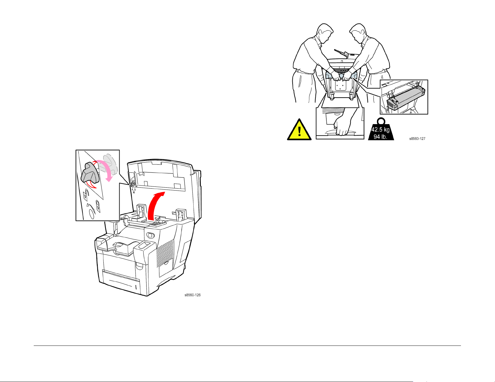
• Always secure the scanhead shipping restraint on the left side of the scanner to lock the
scanhead before removing the scanner portion of the system. Shipping the scanner with
the scanhead unlocked can damage the scanner.
Figure 2 System Lifting Technique
• Always move the system separately from optional Trays 3 and 4.
When shipping the system, repack the system using the original packing material and boxes or
a Xerox repackaging kit. Additional instructions for repacking the system are provided in the
repackaging kit. If you do not have all the original packaging, or are unable to repackage the
system, contact your local Xerox service representative
CAUTION
Failure to repackage the system properly for shipment can result in damage to the system.
Damage to the system caused by improper moving is not covered by the Xerox warranty, service agreement, or Total Satisfaction Guarantee.
Figure 1 Locking the Scanhead
• Always remove the document feeder before shipping the system.
• Always remove the scanner before shipping the system.
• The system is heavy and must be lifted by two people. The illustration below shows the
proper technique for lifting the system.
Introduction
10/2006
Moving the System
viii
Initial Issue
Phaser 8510/8560MFP Multifunction Product
Symbology and Nomenclature
The following reference symbols are used throughout the documentation.
Warnings, Cautions, and Notes
Warnings, Cautions, and Notes will be found throughout the Service Documentation. The
words WARNING or CAUTION may be listed on an illustration when the specific component
associated with the potential hazard is pointed out; however, the message of the WARNING or
CAUTION is always located in the text. Their definitions are as follows:
WARNING
A Warning is used whenever an operating or maintenance procedure, a practice, condition, or statement, if not strictly observed, could result in personal injury.
CAUTION
A Caution is used whenever an operating or maintenance procedure, a practice, condition, or
statement, if not strictly observed, could result in damage to the equipment.
NOTE: A Note is used whenever it is necessary to highlight an operating or maintenance procedure, practice, condition, or statement.
Table 2 Additional Warnings
REP 5.0.2 Scanner Power Supply
REP 5.0.19 Drum Heater Relay Board
WARNING
HIGH VOLTAGE!
DANGER: HAUTE TENSION!
Exercise care when making the voltage check in the following steps.
DANGER: Soyez extrêmement vigilant lorsque vous effectuez les tests de tension au
cours des étapes qui suivent.
WARNING
Personal injury may result from grasping hot areas of Printhead. If a hot Printhead must
be removed, grasp the Printhead by black plastic frame component.
DANGER: Des blessures peuvent résulter si les zones chaudes du module de four sont
touchées. Si un module de four chaud doit être enlevé, le saisir par l'élément en plastique noir du bâti.
Common Warnings and Safety Icons
The following common warnings are used throughout the documentation and the safety icons
are displayed on the machine. Additional specific warnings are included for the listed sections.
Common Warnings
WARNING
To avoid personal injury or shock, do not perform repair or adjustment activities with
the power switch on or electrical power applied to the machine.
DANGER: Afin d'éviter des blessures ou des chocs électriques, ne pas effectuer des
activités de maintenance ou de réglage avec l'équipement sur Marche ou avec le cordon
d'alimentation branché.
The following sections have additional specific warning information.
Table 1 Introduction and Section 4
Introduction - Symbology and Nomenclature
Section 4 - Repairs and Adjustments
WARNING
A Warning is used whenever an operating or maintenance procedure, a practice, conditioning, or statement, if not strictly observed, could result in personal injury.
DANGER: Une note DANGER est utilisée à chaque fois qu’une procédure de maintenance ou qu’une manipulation présente un risque de blessure si elle n’a pas été strictement observée.
The following sections have additional specific warning information.
Table 2 Additional Warnings
REP 2.0.2 Print head Assembly
REP 2.0.8 Left and Right Printhead Restraints
Machine Safety Icons
The following precautionary symbols may appear on the system.
This symbol indicates DANGER high voltage.
Figure 1 High Voltage Symbol
Protective ground (earth) symbol.
Figure 2 Protective Ground (earth) Symbol
These symbols indicate hot surface on or in the printer. Use caution to avoid personal injury.
Figure 3 Hot Surface Symbol
Initial Issue
Phaser 8510/8560MFP Multifunction Product
10/2006
ix
Introduction
Symbology and Nomenclature

The surface is hot while the printer is running. After turning off the power, wait 30 minutes.
Figure 4 Wait 30 Minutes Symbol
Avoid pinching fingers in the printer. Use caution to avoid personal injury.
Figure 5 Pinch Injury Symbol
Voltage Measurement and Specifications
Measurements of DC voltage must be made with reference to the specified DC Common,
unless some other point is referenced in a diagnostic procedure. All measurements of AC voltage should be made with respect to the adjacent return or ACN wire.
Table 3 Voltage Measurement and Specifications
Voltage Specification
INPUT POWER 220 V 198 VAC TO 254 VAC
INPUT POWER 100 V 90 VAC TO 135 VAC
INPUT POWER 120 V 90 VAC TO 135 VAC
+5 VDC +4.75 VDC TO +5.25 VDC
+24 VDC +23.37 VDC TO +27.06 VDC
Logic Voltage Levels
Measurements of logic levels must be made with reference to the specified DC Common,
unless some other point is referenced in a diagnostic procedure.
Use caution (or draws attention to a particular component). Refer to the manual(s) for information.
Figure 6 Use Caution Symbol
Electrostatic Discharge (ESD) Field Service Kit
The purpose of the ESD Protection Program is to preserve the inherent reliability and quality of
electronic components that are handled by the Field Service Personnel. This program is being
implemented now as a direct result of advances in microcircuitry technology, as well as a new
acknowledgment of the magnitude of the ESD problem in the electronics industry today.
This program will reduce Field Service costs that are charged to PWB failures. Ninety percent
of all PWB failures that are ESD related do not occur immediately. Using the ESD Field Service
Kit will eliminate these delayed failures and intermittent problems caused by ESD. This will
improve product reliability and reduce callbacks.
The ESD Field Service Kit should be used whenever Printed Wiring Boards or ESD sensitive
components are being handled. This includes activities like replacing or reseating circuit
boards or connectors. The kit should also be used in order to prevent additional damage when
circuit boards are returned for repair.
The instructions for using the ESD Field Service Kit can be found in ESD Field Service Kit
Usage in the General Procedures section of the Service Documentation.
Table 4 Logic Levels
Voltage H/L Specification
+5 VDC H= +3.00 TO +5.25 VDC
L= 0.0 TO 0.8 VDC
+24 VDC H= +23.37 TO +27.06 VDC L= 0.0 TO 0.8 VDC
DC Voltage Measurements in RAPs
The RAPs have been designed so that when it is required to use the DMM to measure a DC
voltage, the first test point listed is the location for the red (+) meter lead and the second test
point is the location for the black meter lead. For example, the following statement may be
found in a RAP:
There is +5 VDC from TP7 to TP68.
In this example, the red meter lead would be placed on TP7 and the black meter lead on TP68.
If a second test point is not given, it is assumed that the black meter lead may be attached to
the copier frame.
Introduction
Symbology and Nomenclature
10/2006
x
Initial Issue
Phaser 8510/8560MFP Multifunction Product

Electrostatic Discharge Precautions
Some semiconductor components, and the respective sub-assemblies that contain them, are
vulnerable to damage by Electrostatic discharge (ESD). These components include Integrated
Circuits (ICs), Large-Scale Integrated circuits (LSIs), field-effect transistors and other semiconductor chip components. The following techniques will reduce the occurrence of component
damage caused by static electricity.
Be sure the power is off to the chassis or circuit board, and observe all other safety precautions.
• Immediately before handling any semiconductor components assemblies, drain the electrostatic charge from your body. This can be accomplished by touching an earth ground
source or by wearing a wrist strap device connected to an earth ground source. Wearing a
wrist strap will also prevent accumulation of additional bodily static charges. Be sure to
remove the wrist strap before applying power to the unit under test to avoid potential
shock.
• After removing a static sensitive assembly from its anti-static bag, place it on a grounded
conductive surface. If the anti-static bag is conductive, you may ground the bag and use it
as a conductive surface.
• Do not use freon-propelled chemicals. These can generate electrical charges sufficient to
damage some devices.
• Do not remove a replacement component or electrical sub-assembly from its protective
package until you are ready to install it.
• Immediately before removing the protective material from the leads of a replacement
device, touch the protective material to the chassis or circuit assembly into which the
device will be installed.
• Minimize body motions when handling unpacked replacement devices. Motion such as
your clothes brushing together, or lifting a foot from a carpeted floor can generate enough
static electricity to damage an electro-statically sensitive device.
• Handle IC’s and EPROM’s carefully to avoid bending pins.
• Pay attention to the direction of parts when mounting or inserting them on Printed Circuit
Boards (PCB’s).
Regulatory Specifications
Xerox has tested this product to electromagnetic emission and immunity standards. These
standards are designed to mitigate interference caused or received by this product in a typical
office environment.
United States (FCC Regulations)
This equipment has been tested and found to comply with the limits for a Class A digital device,
pursuant to Part 15 of the FCC Rules. These limits are designed to provide reasonable protection against harmful interference when the equipment is operated in a commercial environment. This equipment generates, uses, and can radiate radio frequency energy. If it is not
installed and used in accordance with these instructions, it may cause harmful interference to
radio communications. Operation of this equipment in a residential area is likely to cause harmful interference in which case the user will be required to correct the interference at his/her own
expense.
If this equipment does cause harmful interference to radio or television reception, which can be
determined by turning the equipment off and on, the user is encouraged to try to correct the
interference by one or more of the following measures:
• Reorient or relocate the receiver.
• Increase the separation between the equipment and receiver.
• Connect the equipment into an outlet on a circuit different from that to which the receiver
is connected.
• Consult the dealer or an experienced radio/television technician for help.
Any changes or modifications not expressly approved by Xerox could void the user's authority
to operate the equipment. To ensure compliance with Part 15 of the FCC rules, use shielded
interface cables.
Canada (Regulations)
This Class A digital apparatus complies with Canadian ICES-003.
Cet appareil numérique de la classe A est conforme
à la norme NMB-003 du Canada.
Initial Issue
Phaser 8510/8560MFP Multifunction Product
European Union
This is a class A product. In a domestic environment this product may cause radio interference
in which case the user may be required to take adequate measures.
Xerox Corporation declares, under our sole responsibility, that the product to which this declaration relates is in conformity with the following standards and other normative documents:
10/2006
xi
Electrostatic Discharge Precautions, Regulatory
Introduction
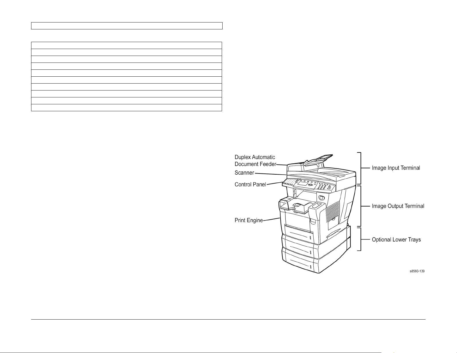
Table 1 Low Voltage Directive 73/23/EEC as amended
EN 60950-1:2001
Table 2 Electromagnetic Compatibility Directive 89/336/EEC as amended
EN 55022:1998 +A1:2000 +A2:2003
EN 55024:1998 +A1:2000 +A2:2003
EN 61000-3-2:2000
EN 61000-3-3:1994
IEC 61000-4-2:1995
IEC 61000-4-3:1995
IEC 61000-4-4:1995
IEC 61000-4-5:1995
IEC 61000-4-6:1996
IEC 61000-4-11:1994
This product, if used properly in accordance with the user’s instructions, is neither dangerous
for the consumer nor for the environment.
A signed copy of the Declaration of Conformity for this product can be obtained from Xerox.
Phaser 8510/8560MFP Overview
The Phaser 8510/8560MFP uses a Printhead and four-color (YMCK) solid-ink sticks, with an
image processor supporting PostScript 3 and PCL5c page description languages. The system
is a high performance, Letter or A4, 24 (8510MFP) or 30 (8560MFP) page per minute (ppm)
multifunction product, supporting resolutions up to 525 x 1200 dots-per-inch (dpi). The product
features USB, Fax, and 10/100 base T Ethernet ports, with an optional Foreign Device Interface (FDI) for specialized installations. The 8510/8560MFP provides a 100-sheet Tray 1 from
which specialty media, card stock, and envelopes are fed. Tray 1 also supports manual feeding. Tray 2 provides 525 sheets of capacity. The Output Tray holds 250 sheets facedown. On
most configurations an Automatic Document Feeder (DADF) is installed providing enhanced
document handling functionality.
Phaser 8510/8560MFP options add memory, media capacity and functionality. RAM memory
upgrades are available to raise installed memory to the 1 GB maximum. A 525-Sheet Feeder is
also available. Two 525-Sheet Feeders may be installed to raise the maximum media input
storage capacity to 1675 sheets. A Configuration Card stores system model identity and configuration parameters.
After a predefined period of time since its last activity, the Phaser 8510/8560MFPP enters a
power saver standby mode. All communications interfaces remain active and have the ability to
wake the system up.
Introduction
Regulatory Specifications, Phaser 8510/8560MFP
10/2006
xii
Figure 1 Phaser 8510/8560MFP Multifunction Product with Optional Trays
Initial Issue
Phaser 8510/8560MFP Multifunction Product

System Configurations
Standard Features
The Phaser 8510/8560MFP offers these standard features:
• Maximum print speed (pages per minute) based on letter-size plain paper:
NOTE: Print speeds for media fed from Tray 1 may be up to 50% slower.
Table 1 Phaser 8510/8560MFP Print Speeds
Phaser 8510MFP Multifunction Product Phaser 8560MFP Multifunction Product
PostScript Print Quality Modes:
– Fast Color: 24 ppm
– Enhanced: 12 ppm
PCL Print Quality Modes:
– 300 x 600 dpi: 13 ppm
– 600 x 600 dpi: 6 ppm
PostScript Print Quality Modes:
– Fast Color: 30 ppm
– Standard: 24 ppm
– Enhanced: 16 ppm
– High Resolution/Photo: 10 ppm
PCL Print Quality Modes:
– 300 x 600 dpi: 16 ppm
– 600 x 600 dpi: 8 ppm
Product Options
Phaser Multifunction Product options include:
• Additional Trays
• Memory
•System Cart
Additional Trays
Trays 1 and 2 are standard on all configurations. The following additional tray combinations are
supported:
• One 525-Sheet Feeder (Tray 3)
• Two 525-Sheet Feeders (Trays 3 and 4)
Memory
All configurations have two memory slots supporting 512 MB, and 1 GB SODIMM modules (up
to maximum of 1 GB DDR2).
System Cart
The System Cart supports a fully-optioned system and provides space for media storage.
• First-page-out: 8 seconds for color prints, 15 seconds for color copies
• Copy, Print, Scan, Fax capabilities (options vary according to configuration and memory)
• Connections: USB, Ethernet 10/100/1000 Base-Tx, RJ-11 Fax Modem, Foreign Device
Interface
Available Configurations
Table 2 lists the standard configurations.
Table 2 Phaser 8510/8560MFP Standard Configurations
Features 8510MFP/N 8510MFP/D 8560MFP/D 8560MFP/T 8560MFP/X
Memory 512 MB 512 MB
Hard Drive No No Yes Yes Yes
Flash Disk Yes Yes No No No
Automatic 2-sided
Printing (DADF)
525-Sheet Feeder No* No* No* Yes Yes
System Cart No* No* Yes Yes Yes
Copy Yes Yes Yes** Yes** Yes**
Scan to PC Yes Yes Yes Yes Yes
Scan to E-mail Yes Yes Yes Yes Yes
Scan to Hard Drive No No Yes Yes Yes
Fax Yes Yes Yes** Yes** Yes**
* This option can be purchased separately for this configuration.
** Hard Drive enables advanced features on this configuration.
No Yes Yes Yes Yes
(2x256)
512 MB 512 MB 512 MB
Metered Printing
Metered printing (PagePack), involves the combination of control software and specialized Ink
Sticks to meter system activity for billing purposes. The Configuration page lists Metered Ink as
Enabled when metering is enabled.
Metered Operation
When a metered printer is initialized at first power-up, the customer sets the printer to Metered
operation using a unique, factory-supplied, 4-digit PIN. Once set to Metered operation, the control software performs the following:
1. The Mode and PIN-entered values in Engine Control Board NVRAM are set.
2. The Control Panel momentarily displays “Metered Ink is now enabled”, then returns to
“Ready” (if no other errors).
3. The First Time Tips pages and the Configuration page are printed.
If an incorrect PIN is entered, “Incorrect numeric password” displays with a prompt “Retry” or
“Do not retry.” Retry returns to the enter prompt, “Do not retry” returns to the Replace Ink Stick
error message. The error persists until the correct PIN is entered.
NOTE: The Hidden Service menu provides an Enable Metered Ink option to restore the
Metered mode parameters to NVRAM should they become lost or corrupt.
Metered Ink
To support metered printing, metered Ink Sticks are available in all four colors. The shape of
the metered Ink Stick differs from the non-metered versions.
Initial Issue
Phaser 8510/8560MFP Multifunction Product
10/2006
xiii
Introduction
System Configurations
Parts of the Product
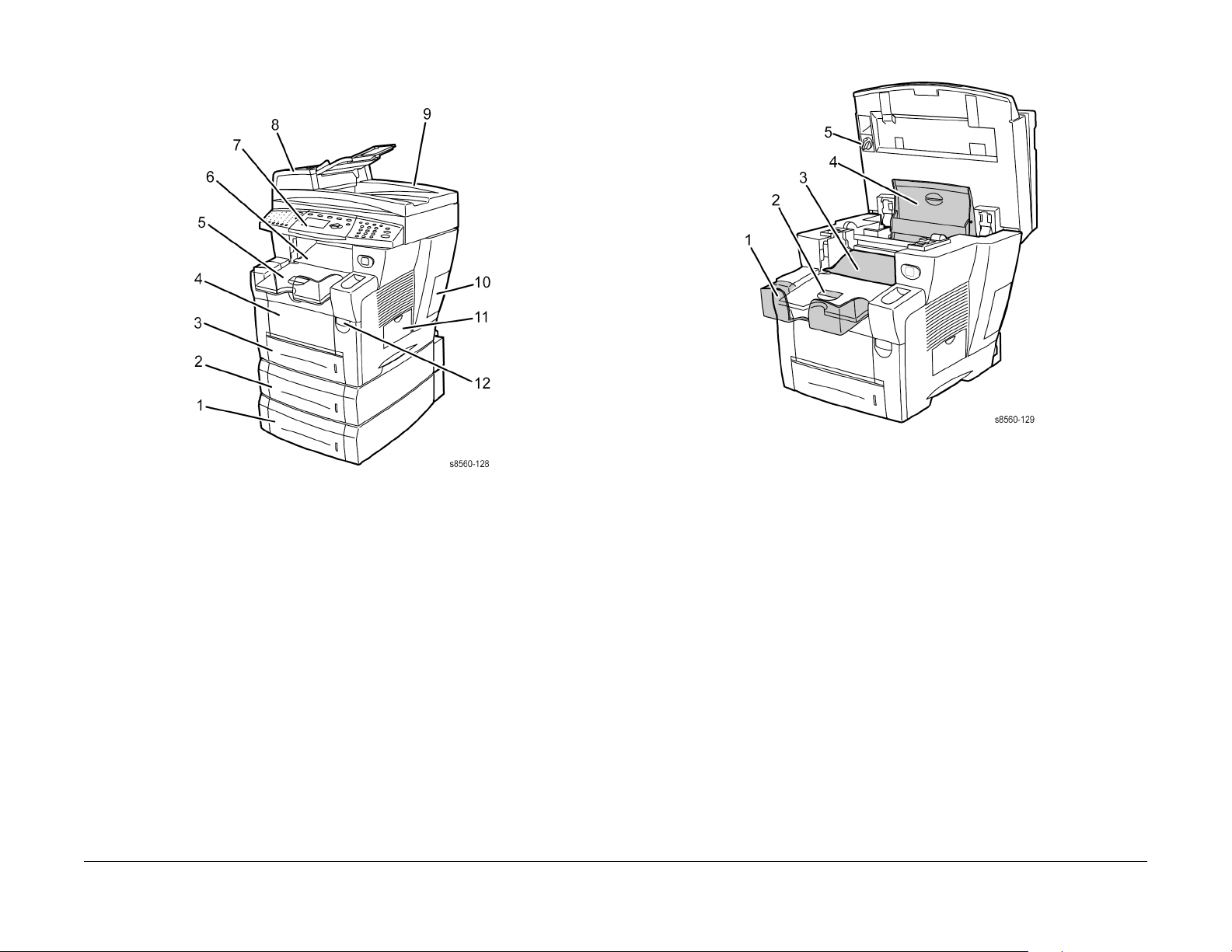
Front View
Figure 1 Front View
1. Tray 4 (optional)
2. Tray 3 (optional)
3. Tray 2
4. Tray 1 (MPT)
5. Output Tray
6. Exit Cover
7. Control Panel
8. Duplex Automatic Document Feeder (DADF) Front Cover
9. DADF
10. Interface Cover
11. Drum Maintenance Kit and Waste Tray access
12. Front Door Latch
Open View
Figure 2 Open View
1. Output Tray
2. Short Paper Stop
3. Exit Cover
4. Ink Loader Cover
5. Scan Head Lock
Introduction
Parts of the Product
10/2006
xiv
Initial Issue
Phaser 8510/8560MFP Multifunction Product
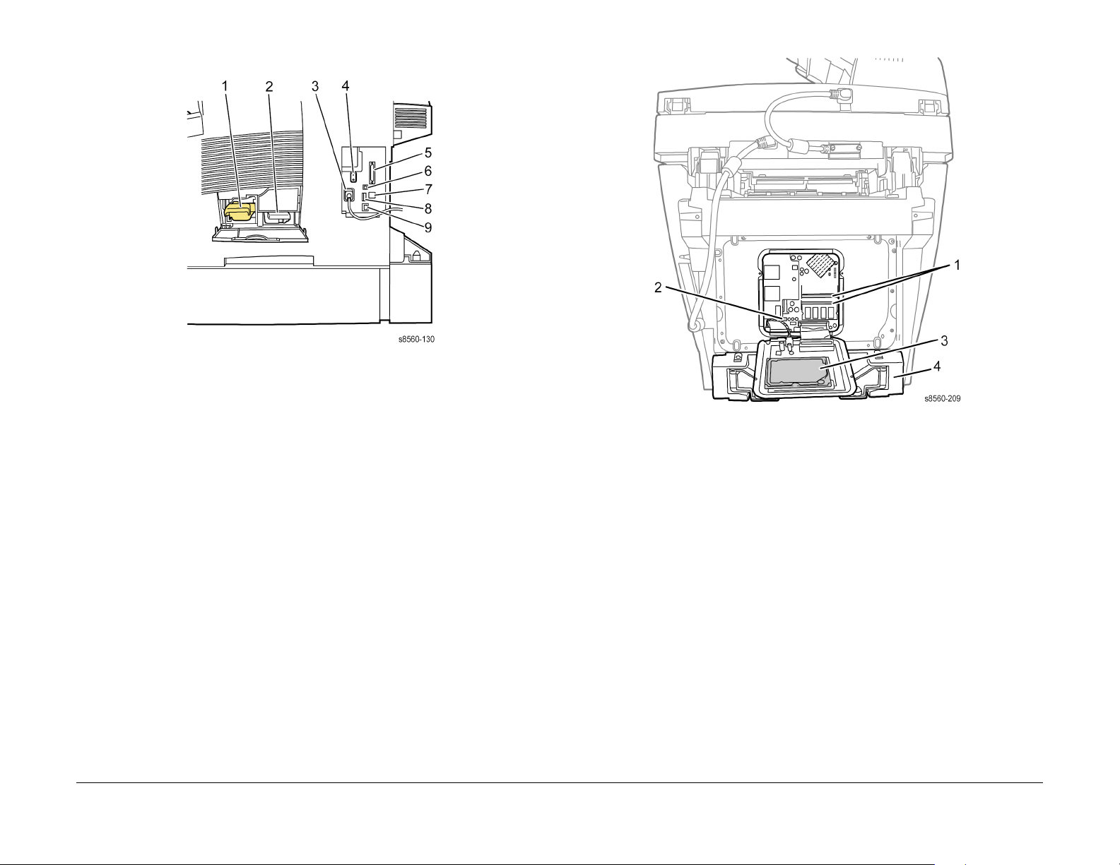
Side View with Interface Connections
Figure 3 Side View with Interface Connections
1. Drum Maintenance Kit
2. Waste Tray
3. AC Power Cord Connection
4. Power Switch
5. Scanner Cable Connection
6. USB Connection
7. Ethernet Connection
8. Configuration Card
9. RJ-11 Fax Modem Connection
Back View - Electronics Module
The system’s main electronics and power supply are enclosed in a metal case called the Electronics Module. The rear panel allows access to the electronics module, RAM, and NVRAM
chips. The system’s Hard Drive is mounted on the rear panel.
Figure 4 Back View
1. RAM Connectors
2. NVRAM Device
3. Hard Drive
4. Printer Stabilizer
NOTE: When replacing the electronics module, transfer these components to the new module.
•RAM
• Configuration Card
• NVRAM Device
• Hard Drive or Flash Disk
Initial Issue
Phaser 8510/8560MFP Multifunction Product
10/2006
xv
Introduction
Parts of the Product

Routine Maintenance Items
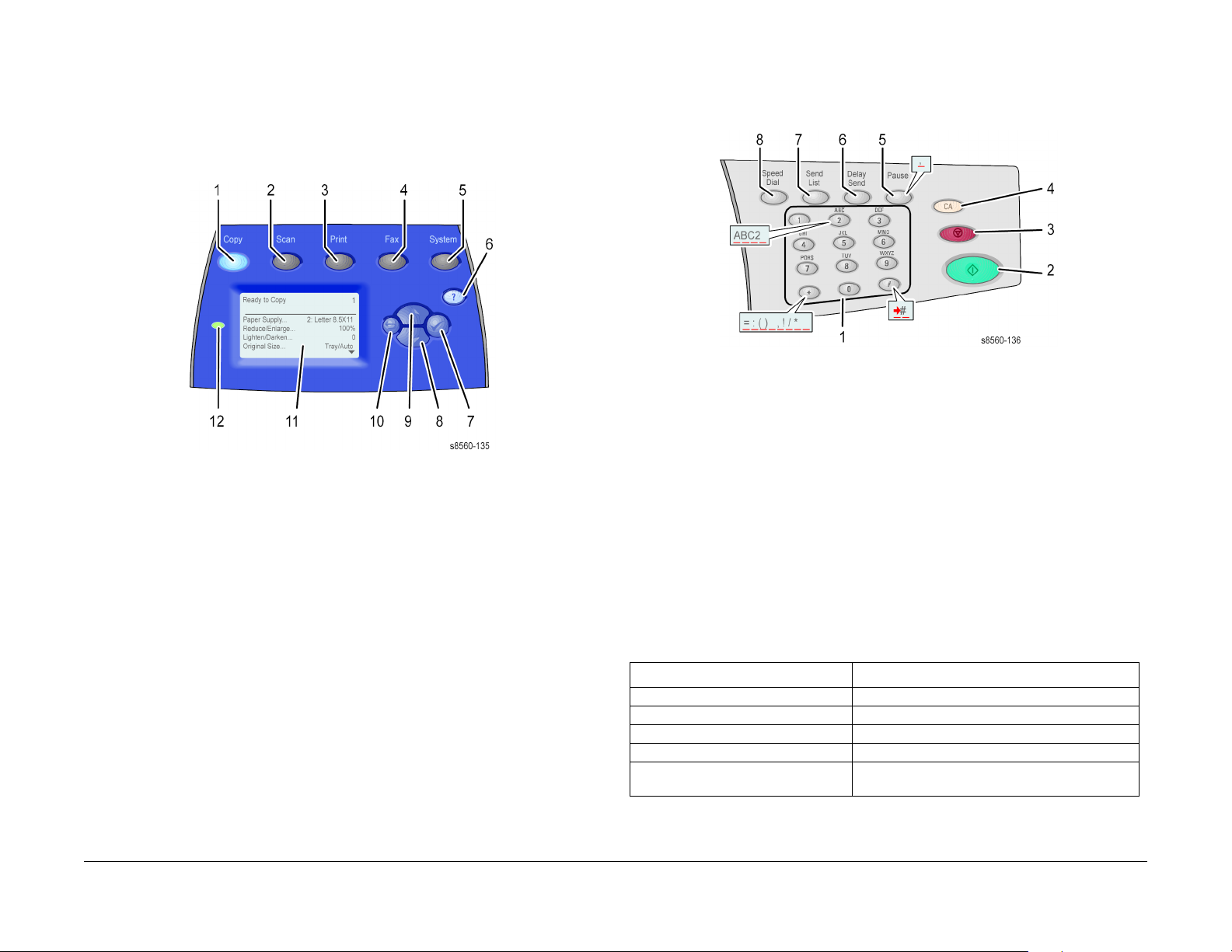
Control Panel Layout
The Control Panel functions are segregated into three areas.
Figure 1 Control Panel
Table 1 Control Panel Functional Areas
Left Side Center Right Side
Copy, Scan, and Fax functions
and indicator LEDs
Control Panel Left
The left side of the control panel contains the following copy, scan, and fax function buttons and
LEDs. A lighted LED indicates the current selection. Figure 2 shows each function’s location.
Display, Mode, Navigation buttons, and status LED’s
Numeric keypad, Stop, Start,
Clear, and Clear All buttons
Figure 5 Routine Maintenance Items and Consumables
Table 1 Routine Maintenance Life Expectancy
Routine Maintenance Items
Extended-Capacity Maintenance Kit 30,000 cycles (0-20% coverage)
20,000 cycles (20-100%) coverage.
Standard-Capacity Maintenance Kit 10,000 cycles
Waste Tray Empty every 7 Purges
DADF Pick Rollers and Separator Pad 50,000 scans
Introduction
Parts of the Product, Control Panel Layout
Figure 2 Left Side Control Panel
1. Color Mode selects black and white or color for copy or scan jobs.
2. Document Type selects the type of document (photo, graphic, mixed text and graphics, or
text only), for copy or scan jobs.
3. Output Quality selects the output quality mode for copies: fast color, standard, enhanced,
or high-resolution/photo.
4. 2-Sided selects either one or 2-sided for the original and one- or 2-sided for the output.
5. Lighten/Darken selects a setting for copy, scan, or fax jobs.
6. Reduce/Enlarge selects scale percentage for output: 25, 50, 100, 150, 200, 400.
10/2006
xvi
Phaser 8510/8560MFP Multifunction Product
Initial Issue
7. The Down Arrow reduces the reduce/enlarge percentage in one percent increments.
8. The Up Arrow increases the reduce/enlarge percentage in one percent increments.
9. Reduce/Enlarge Percentage display indicates the current educe/enlarge setting.
Control Panel Center
The center of the Control Panel contains the display, mode and navigation buttons, as well as
the status LED. Figure 3 shows each function’s location.
Figure 3 Center Control Panel
1. Copy displays the Copy menu.
2. Scan displays the Scan menu.
3. Print displays the Print menu.
4. Fax displays the Fax menu.
5. System displays the System Setup menu.
6. Help(?) provides additional information about the menu or message displayed.
7. OK accepts the highlighted menu selection.
8. Down Arrow scrolls downward through menu selections.
9. Up Arrow scrolls upward through menu selections.
10. Back returns the previous menu to the display.
11. Control Panel display.
12. Status LED uses color to indicate these states of the current function:
• Green indicates the system is ready to print, copy, scan, or fax.
• Yellow indicates a warning condition. The system continues the operation.
• Red indicates a startup or operational error condition.
• Blinking indicates a warm-up or busy condition.
Control Panel Right
The right side of the Control Panel contains the numeric keypad, Start, Stop, and Clear buttons, as well as Fax control functions. Figure 4 shows each function’s location.
Figure 4 Right Side Control Panel
1. Numeric keypad for entering numbers for sending a fax, selecting a number of copies, or
entering a numeric password.
2. Start initiates the selected function (copy, scan. or fax).
3. Stop pauses a print, copy, scan, or fax job. To cancel the job, follow the instructions indicated on the display.
4. Clear All resets all job settings and returns to the top of the default function.
5. Pause enters a pause in a fax number.
6. Delayed Send stores a time for fax transmission.
7. Send List to view or add fax numbers to a list.
8. Speed Dial accesses directories of groups or individual fax numbers.
Control Panel Shortcuts
Table 2 Short Cuts
Mode Press this selection at Power On
Skip execution of POST diagnostics OK
Print Service Diagnostics Map INFO
Reset PostScript NVRAM BACK+ON
Password Bypass UP+DOWN
Enter Service Diagnostics BACK+? before the Xerox logo stops scrolling and
until Beginning Service Mode appears.
Initial Issue
Phaser 8510/8560MFP Multifunction Product
10/2006
xvii
Introduction
Control Panel Layout
Specifications
Functional Specifications
Table 1 Functional Specifications
Characteristic Specifications
Printing Process Four-color (CMYK) solid ink Printhead architecture.
Image System Transfix transfer from oil coated Drum
Color Medium Cyan, Magenta, Yellow, and Black Ink Sticks
Resolution Fast Color: 225 x 400 dpi
Standard: 300 x 450 dpi
Enhanced: 525 x 450 dpi
Photo: 525 x 2400 dpi
First Page-Out (from
Ready)
Warm-up Time Color and Monochrome: 12 minutes from Power On
Memory Specifications
Characteristic Specifications
Minimum RAM 512 MB
Maximum RAM 1 GB
Supported RAM Supports up to 1 GB of DDR2 memory using 2 slots
Flash Disk 256 MB NAND Flash Storage in 8510MFP
Color: 8 seconds
Monochrome: 8 seconds
Table 2 Memory Specifications
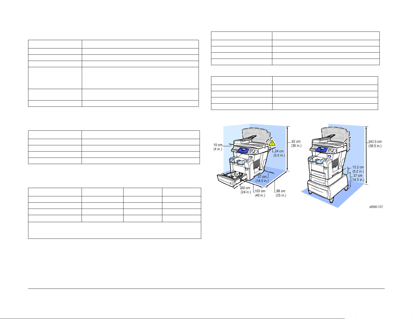
Physical Dimensions and Clearances
Table 4 Print Engine
Dimensions Value
Height 620 mm (24.4 in.)
Width 530 mm (20.9 in.)
Depth 660 mm (26.2 in.)
Weight 42 kg (93 lb.)
Table 5 525-Sheet Feeder
Dimensions Value
Height 132 mm (5.2 in.)
Width 422 mm (16.6 in.)
Depth 514 mm (20.24 in.
Weight 5.2 kg (11.5 lb.)
Media Tray Capacity
Table 3 Tray Capacity
Media and Weight Tray 1 Trays 2 and 3 DADF
Standard Paper 100 Sheets 525 Sheets 50 Sheets
Transparency 100 Sheets 50 Sheets
Envelopes 50
Weight
The DADF accommodates sizes from 114 x 140 mm (4.5 x 5.5 in.) to 216 x 356 mm (8.5 x
14.0 in.). The weight range includes 60-120 g/m2 (16-32 lb. Bond) (22-45 lb.
Cover).
Introduction
75-220 g/m
2
75-255* g/m
2
Specifications
10/2006
xviii
Figure 1 Minimum Clearances
Initial Issue
Phaser 8510/8560MFP Multifunction Product

Print Engine Specifications
Table 6 Print Engine Functional Specifications
Characteristic Specification
Printing process Solid-ink
Controller 500 MHz processor
Color medium Yellow, cyan, magenta, and black ink sticks, each shape-
coded. The system uses the subtractive color system to
produce the colors red, green, and blue
Color Management Automatic, Black & White,
Office: sRGB, Vivid Color, None,
Press: Commercial, Euroscale, SWOP
FPOT, Color Copy < 15 seconds per page/1st copy
subsequent copies at printer speed.
Memory 2 slots; minimum 512 MB, maximum 1 GB, PC133 DRAM
Fonts 137 PostScript 3
81 PCL5c
Warm-up time From Off (cold start): 12 minutes
From power saver: 4 minutes
Table 7 Scanner/DADF Functional Specifications
Characteristic Specification
Noise Standby: < or equal to 45 dB
Scanning: < or equal to 50 dB
Electrical Specifications
Table 8 Electrical Specifications
Characteristic Specification
Primary Line Voltages 90-135 VAC
Primary Line Voltage Frequency Range
Power Consumption at Rated
Voltage Input
Energy Star 70 W
Scanner Power Supply 30 W
180-254 VAC
47 - 63 Hz
300 W (average during printing)
1500 W (peak) - 1000 typical
220 W (idle)
Scanner/DADF Specifications
Table 7 Scanner/DADF Functional Specifications
Characteristic Specification
Printing Process Print Engine
Scan to Capabilities Scan to Disk (mailbox) function
Scan/Copy Process Flatbed platen and C-shape ADF
Copies per Minute DADF: 20 ppm simplex, 10 ppm duplex
Memory 2 MB (1M x 16 SDRAM)
Image Buffer 32 MB SDRAM for Platen
Bit Depth Reading: 48 bits
Optical Resolution 600 x 300 to 600 x 2400 dpi (FS x SS)
Output Resolution from Scan-
ner
Calibration Time less than 2 seconds (performed prior to copier and scan
Power Saver Mode Scanner and DADF are switched OFF. Also, lamps automati-
Scan to PC
Charge Coupled Device scan head
RGB color pack
The scan controller provides 16 bit DMA interface for sending
image data through the scanner board to the image processor board in the electronics module.
128 MB SDRAM for DADF
Output: 24 bits
Always equals optical resolution
operations)
cally turn off after 20 minutes.
Environmental Specifications
Table 9 Environmental Specifications
Characteristic Specification
Operating Storage
Temperature
Humidity 10% - 80% RH Non-Condensing
Altitude 0 to 2,438 meters (8,000 ft.) 0 to 6,092 meters (20,000 ft.)
Acoustic Noise (db) Operating Mode Standby Mode
º
- 32º C / 50º - 90º F operating
10
operating
-30°C to 60°C (-22 F to 140 F)
30% to 95% RH, non-condensing
Initial Issue
Phaser 8510/8560MFP Multifunction Product
10/2006
xix
Introduction
Specifications

Image Specifications
Table 10 Print Engine Only Skew Specifications
Characteristic Specification
Printed Left Side Margin 5.0 mm +
Leading Edge Margin 5.0 mm +
NOTE: To derive the skew specification for a particular media size, measure the width of the
leading edge in millimeters. Next, divide the measured length by 1000, then multiply by the
appropriate Image Area Tolerance specification in milli-radians. For example, A 5 in. by 7 in.
custom page would have a leading edge width, in millimeters, of 127mm (5 in.). Dividing the
127 by 1000 (127/1000), then multiplying the result by the 11 milli-radians specification results
in a maximum skew of 1.4 mm (127/1000) x 11 = 1.4 mm.
Table 11 System Skew Specifications Scan, Copy, Print
Characteristic Specification
Printed Left Side Margin 5.0 mm +
Leading Edge Margin 5.0 mm +
Image Area Tolerance Zone
Image Skew, Envelopes 15.5 milli-radians max across the width of the leading edge.
Image Skew, Index Card 18.0 milli-radians max across the width of the leading edge.
Image Skew, All other sizes 11.0 milli-radians max across the width of the leading edge.
Characteristic Specification
Maximum Print Area 302 mm x 1194 mm
Guaranteed Image Area 297 mm x 1194 mm
Resolution/Gradation Fast Color: 300 x 300 dpi
Standard: 300 x 450 dpi
Enhanced: 563 x 400 dpi
Photo/Hi Res: 525 x 1200 dpi
2.0 mm (0.197 in. + .080 in.)
1.3 mm (0.197 in. + .050 in.)
4.0 mm (0.197 in. + .157 in.)
3.3 mm (0.197 in. + .130 in.)
Table 12 Image Specifications
Media and Tray Specifications
The media trays accommodate most sizes and types of paper, transparencies, or other specialty media. Print the Paper Tips page for a list of supported media.
Media that May Damage the System
The system can use a variety of media for print and copy jobs. However, some media can
cause poor output quality, increased jams, or damage. Unacceptable media includes:
• Rough, plastic, or porous media
• Paper that has been stapled, folded, photocopied, or wrinkled
• Envelopes with windows, metal clasps, padding, or adhesives with release strips
• CD labels
• Media that is less than 60 g/m2 or more than 220 g/m2
Media Storage Guidelines
If media handling problems are a common occurrence, review the following storage guidelines
with the customer.
• Store paper in dark, cool, relatively dry locations. Most paper items are susceptible to
damage from ultraviolet (UV) and visible light. UV radiation, which is emitted by the sun
and fluorescent bulbs, is particularly damaging to paper items. The intensity and length of
exposure to visible light on paper items should be reduced as much as possible.
• Maintain constant temperatures and relative humidity
• Avoid light, heat, and dampness.
• Avoid attics, kitchens, garages, and basements for storing paper. Inside walls are drier
than outside walls where moisture can collect.
• Store paper flat. Paper should be stored on pallets, cartons, shelves, or in cabinets.
• Avoid having food or drinks in the area where paper is stored or handled.
• Do not open sealed packages of paper until needed. Leave paper in the original packaging. For most commercial grades, the wrapper’s inner lining protects the paper.
• Some specialty media is packaged inside sealed plastic bags. Leave the media inside the
bag until needed; return unused media to the bag.
DADF Media Guidelines
The DADF accommodates sizes from 114 x 140 mm (4.5 x 5.5 in.) to 216 x 356 mm (8.5 x 14.0
in.), with weights within the following range: 60–120 g/m2 (16–32 lb. Bond) (22–45 lb. Cover).
Follow these guidelines when loading originals into the document feeder:
• Load originals face-up, so the top of the document enters first.
• Place only loose sheets of paper in the document feeder.
• Adjust the paper guides so they fit against the originals.
• Insert paper in the document feeder only when the ink on the paper is completely dry.
Use the glass rather than the document feeder to copy or scan the following types of originals:
• Paper with paper clips or staples attached
• Paper with wrinkles, curls, folds, tears, or notches
• Coated or carbonless paper, transparencies, or items other such as cloth or metal
• Envelopes
Supported Media
The following sections provide information about paper sizes and weights that can be used in
the system trays. For more detailed information about supported paper and other media, print
the Paper Tips page:
1. On the Control Panel, press the System button.
2. Select Information, and then press the OK button.
3. Select Information Pages, and then press the OK button.
4. Select Paper Tips, and then press the OK button to print.
See also: Recommended Media List at www.xerox.com/paper
Introduction
Specifications
10/2006
xx
Initial Issue
Phaser 8510/8560MFP Multifunction Product

Service Call Procedures.................................................................................................. 1-3
Initial Actions................................................................................................................... 1-4
Routine Maintenance Activities ....................................................................................... 1-5
Cleaning Procedures....................................................................................................... 1-5
Final Actions.................................................................................................................... 1-6
1 Service Call Procedures
Initial Issue
Phaser 8510/8560MFP Multifunction Product
10/2006
1-1
Service Call Procedures

Service Call Procedures
This section describes an overview of the steps a service technician should take, using this
manual, to service the system and attached options. The system’s diagnostic routines report
problems using error messages and fault codes displayed on the Control Panel, logged in the
Service Usage Profile, or by flashing LEDs. These error indications serve as the entry point
into the troubleshooting process. System problems not directly indicated by or associated with
an error message or fault code are covered in Section 6, General Procedures. Print-quality
problems are covered in Section 3, Image Quality.
The steps listed here are a guide for performing any service on this system. If you choose not
to use these steps, it is recommended that you start at the appropriate troubleshooting procedure and proceed from there. When servicing the system, follow the safety measures detailed
in Service Safety Summary.
1. Identify the problem.
• Verify the reported problem does exist.
• Check for any error codes and write them down.
• Print normal customer prints and service test prints.
• Make note of any print-quality problems in the test prints.
• Make note of any mechanical or electrical abnormalities present.
• Make note of any unusual noise or smell coming from the printer.
• Print a Service Usage Profile, if the printer is able to print.
• View the Engine Error and Jam Histories under the Service Tools menu.
• Verify the AC input from the wall outlet is within specifications.
2. Inspect and clean the system.
• Follow the cleaning instructions given in Section 6.
• Verify that the power cord is in serviceable condition.
• Restart the system to check if the error reoccurs.
3. Find the cause of the problem.
• Use the troubleshooting procedures to find the root cause of the problem.
• Use Service Diagnostics to check the system and optional components.
• Use the Wiring Diagrams and Plug/Jack Locator to locate test points.
• Take voltage readings as instructed in the troubleshooting procedure.
4. Correct the problem.
• Use the Parts List to locate a part number.
• Use the Repair procedures to replace the part.
5. Final checkout
• Test the printer to verify the problem is corrected and no new problems arose.
Accessing Engine Fault History
Listed below are three ways in which you can access fault history records.
1. Print (if possible) the Status page from the Troubleshooting menu --> Service Tools. The
Engine Error History and Jam History are listed on the second page of the report.
2. View the system’s fault history on the Control Panel. Go to Troubleshooting->Service
Tools --> Engine Error History.
NOTE: Definitions of the codes that appear in the Fault and Jam History appear in Section 2.
3. If the system is connected to a network and has a TCP/IP address, view the system’s web
page using a web browser.
a. Open a web browser.
b. Enter the system’s IP address as the URL.
c. Select the Support --> Troubleshooting --> Diagnostics Logs and the fault history dis-
plays.
Technician’s Tool Kit
Table 1 lists required, recommended, and optional tools used to service this and other similar
products.
Table 1 Service Tools
Description Detail
Required Tools
Torx Driver Bits T5, T8, T10, T15, T20
Phillips Drivers Phillips # 2 and # 1 5.0 x 75 mm, 3.0 x 75 mm, 6.0 x 100 mm
Flathead Drivers 5.0 x 75 mm, 3.0 x 75 mm
Torque Screw Driver Required for this system P/N 003082700
Hex Bit 2.5mm Hex Bit, T-20 P/N 003086600
Driver Extension
Small Channel lock Pliers
Needle Nose Pliers
Wire Cutters
Flashlight
Assorted Nut Drivers
Lint-Free Cloths
Lubricant/Grease Reolube P/N 070E00890
Cleaners Multipurpose surface cleaner and Alcohol
ESD Strap
Highly Recommended Tools
Nut Driver 5.5mm (magnetic) P/N 600T2123
Network Cross-over cable Tech
Scanner Calibration page P/N 109K01910
Toner Vac Toner and general cleaning
Multimeter Volts, Ohms, Current
Initial Issue
Phaser 8510/8560MFP Multifunction Product
10/2006
1-3
Service Call Procedures
Service Call Procedures

Table 1 Service Tools
Description Detail
Optional Tools
Canned Air
3 -Prong Claw Part-Retriever
Pointer with Magnetized Head
Tweezers
Utility Knife
Dental Mirror
Screw Box
Soldering Iron
Heat Shrink tubing
Electrical Tape
Jeweler's Screwdriver Kit
Precision/Hobby tool set phillips, flathead, pliers, small torx drivers
Serial & Parallel Loop Back
Plugs
Bootable CDs and Floppy
Disks
IC Chip Puller
Initial Actions
Purpose
Use the following procedure to determine the reason for the service call and to identify and
organize the actions which must be performed.
Procedure
1. Gather the information about the service call and the condition of the copier/printer.
a. Question the operator(s). Ask about the location of most recent paper jams. Ask
about the image quality and the copier/printer performance in general, including any
unusual sounds or other indications.
b. After informing the customer that the machine will not be available for copying and
printing, disconnect the machine from the customer’s network.
c. If a new installation, be sure all packing material is removed.
d. Check that the power cords are in good condition, directly plugged in to the power
source, and free from defects. Repair or replace the power cords as required. Check
that the circuit breaker, if present, is not tripped.
e. If the system appears is inoperative, go to Electrical Troubleshooting and repair the
problem. Then continue below.
f. Inspect any rejected copies. Inquire as to, or otherwise determine, the paper quality
and weight. Print the Paper Tips page for specific media specifications. Look for any
damage to the copies, oil marks, image quality defects, or other indications of an
unreported problem.
NOTE: If a fault code is displayed while performing a diagnostics procedure, go to
that fault code RAP and repair the fault. Return to Diagnostics and continue with the
procedure that you were performing.
g. Display and review the information in the Fault History, Jam History, Service Usage
Profile. Classify this information into categories:
Information that is related to the problem that caused the service call.
Information that is related to secondary problems.
Information that does not require action, such as a single occurrence of a prob-
lem.
2. Perform any required routine maintenance activities. Refer to the Routine Maintenance
Activities section.
3. If any DADF feed jams are reported, or fault codes are logged, replace the Feed Roll Kit.
4. Try to duplicate the problem by running the same jobs that the customer ran once repairs
are complete to verify repairs are effective.
5. Go to General Procedures to further investigate the problem.
Service Call Procedures
Service Call Procedures, Initial Actions
10/2006
1-4
Initial Issue
Phaser 8510/8560MFP Multifunction Product

Routine Maintenance Activities
Procedure
1. Clean the Pick Rollers on every call.
2. Use the Control Panel to check maintenance item counters.
3. Compare the counter values to those listed in Table 1.
4. Advise the customer of any routine maintenance items that are approaching or over the
service limit.
Table 1 Routine Maintenance Item Life Expectancy
Routine Maintenance Items
Extended-Capacity Maintenance Kit 30,000 cycles (0-20% coverage)
20,000 cycles (20-100%) coverage.
Standard-Capacity Maintenance Kit 10,000 cycles
Waste Tray Empty every 7 Purges
DADF Pick Rollers and Separator Pad 50,000 scans
Cleaning Procedures
Purpose
The purpose is to provide cleaning procedures to be performed at every call.
Procedure
CAUTION
Do not use any solvents unless directed to do so in this manual.
General Cleaning
Use a dry lint free cloth or a lint free cloth moistened with water for all cleaning unless directed
otherwise in this manual. Wipe with a dry, lint free cloth if a moistened cloth is used.
1. Feed Components (Rolls and Pads)
Follow the General Cleaning procedure above.
2. Jam Sensors
Clean the sensors with a dry cotton swab.
3. Scanner
a. Using the optical Cleaning Cloth, clean the Document Glass.
b. Clean the Document Cover.
4. DADF
Check the paper path for debris or damage. Clean the rolls with a clean cloth and Film
Remover as required.
Initial Issue
Phaser 8510/8560MFP Multifunction Product
10/2006
1-5
Service Call Procedures
Routine Maintenance Activities, Cleaning Proce-

Final Actions
Purpose
The intent of this procedure is to be used as a guide to follow at the end of every service call.
Procedure
1. Check that the exterior of the system and the adjacent area is clean. Use a dry cloth or a
cloth moistened with water to clean the exterior of the system. Do not use solvents.
2. Check the supply of consumables. Ensure that an adequate supply of consumables is
available according to local operating procedures.
3. Conduct any operator training that is needed. Ensure the operator understands the periodic maintenance procedures in the User Guide.
4. Reconnect the system to the customer network. Verify function by printing one or more
test prints. Present these to the customer as examples of system performance.
5. Issue copy credits as needed.
6. Discuss the service call with the customer to ensure that the customer understands what
has been done and is satisfied with the results of the service call.
Service Call Procedures
Final Actions
10/2006
1-6
Initial Issue
Phaser 8510/8560MFP Multifunction Product

Power On Self Tests ....................................................................................................... 2-3
NVRAM Reset................................................................................................................. 2-5
Error Message Troubleshooting...................................................................................... 2-7
1,00X.4x 525-Sheet Feeder Faults ................................................................................. 2-8
1,000.6x 525-Sheet Feeder Program Faults................................................................... 2-9
2,00X.xx I/O Board Errors............................................................................................... 2-9
2,006.xx I/O Board Program Faults................................................................................. 2-10
2,0XX.6x Configuration Card Faults................................................................................ 2-10
3,0XX.6x IPC Program Faults......................................................................................... 2-11
4,0xx.4x Process Control Errors ..................................................................................... 2-11
4,024.42 Wiper Alignment Fault...................................................................................... 2-12
4,025.46 Drum Transfix Fault.......................................................................................... 2-12
4,0xx.6x Process Control Program Faults....................................................................... 2-13
5,0xx.4x Y-Axis Sub-System Faults................................................................................ 2-13
5,0xx.6x Y-Axis Sub-System Program Faults ................................................................. 2-14
6,0xx.4x X-Axis Fault ...................................................................................................... 2-15
6,0xx.6x X-Axis Program Faults...................................................................................... 2-15
7,002.44 Process Drive Fault.......................................................................................... 2-16
7,006.4x Head Tilt Solenoid Fault................................................................................... 2-16
7,007.49 Process Drive Fault.......................................................................................... 2-17
7,008.41 Printhead Tilt Fault........................................................................................... 2-17
7,009.42 Printhead Restraint Fault ................................................................................. 2-18
7,01X.4x Process Faults ................................................................................................. 2-19
7,0xx.6x Program Faults ................................................................................................. 2-20
8,0XX.4x Wiper or Media Drive Faults............................................................................ 2-21
8,0xx.6x Media Drive Program Faults............................................................................. 2-22
9,0XX.4x Ink Loader Faults............................................................................................. 2-22
9,009.44 and 9,00X.6x Ink Loader Program Faults ........................................................ 2-23
11,0XX.xx Electronics Module Interface Faults............................................................... 2-24
11,100.60 Electronics Module Temperature Fault .......................................................... 2-25
12,000.60 Program Faults............................................................................................... 2-25
13,000.48 Printhead Thermal Fault................................................................................. 2-26
13,003.42 and 13,007.46 Thermal Faults ....................................................................... 2-26
13,008.47 and 13,010.49 Drum Thermal Faults ............................................................. 2-27
13,067.43, 13,069.45, 13,071.47 Drum Temp Sensor Faults ......................................... 2-28
13,XXX.4x Preheater Thermal Faults ............................................................................. 2-28
13,1XX.4x Left Jetstack Thermal Faults ......................................................................... 2-29
13,2XX.4x Right Jetstack Thermal Faults....................................................................... 2-29
13,XXX.xx Printhead Reservoir Thermal Faults.............................................................. 2-30
13,XXX.xx Ink Loader Thermal Faults ............................................................................ 2-30
13,00x.6x Thermal Program Faults................................................................................. 2-31
19,0XX.4x Printhead Calibration Faults .......................................................................... 2-32
19,0XX.6x Waveform Program Faults............................................................................. 2-32
21,000.69 Diagnostic Firmware Version Mismatch......................................................... 2-33
22,0XX.6x Jam Fault....................................................................................................... 2-33
23,0XX.6x NVRAM Faults............................................................................................... 2-34
26,0XX.6x Printing Faults................................................................................................ 2-34
27,0XX.6x Profile Library ................................................................................................ 2-35
2 Error Messages and Codes
29,0XX.6x Jam Manager Faults ...................................................................................... 2-35
31,001.40 Mechanical Initialization Jam.......................................................................... 2-36
31,0XX.6x Program Faults.............................................................................................. 2-36
33,00X.4x Tray 1 Width Sensor Faults............................................................................ 2-37
34,00X.4x Printhead NVRAM Faults ............................................................................... 2-37
36,000.40 Drum Maintenance Faults .............................................................................. 2-38
36,001.67 Drum Maintenance Drive Faults..................................................................... 2-38
36,002.44 Drum Maintenance Kit Fault........................................................................... 2-39
37,0XX.xx PEST Heater Faults....................................................................................... 2-39
37,01X.41 PEST Fan Faults............................................................................................ 2-40
37,016.43 PEST 50 Volt Supply Fault............................................................................. 2-40
37,0XX.4x PEST Clutch/Solenoid Faults ........................................................................ 2-41
37,024.48 PEST Tray 2 Lift Motor Fault.......................................................................... 2-42
37,026.44 PEST Purge Pump Fault................................................................................ 2-42
37,02X.4x PEST Relay Board Faults .............................................................................. 2-43
37,03X.4x PEST X-Axis Motor Faults ............................................................................. 2-43
37,035.44 and 37,036.45 PEST Y-Axis Motor Faults...................................................... 2-44
37,037.46 and 37,038.47 PEST Media Drive Faults....................................................... 2-44
37,039.48 and 37,040.40 PEST Process Drive Faults.................................................... 2-45
37,0XX.4x PEST Power Supply Faults ........................................................................... 2-45
39,002.40 and 39,003.41 Scanner Subsystem Test Faults ............................................ 2-46
39,004.42 Scanhead Locked or Shipping Restraint Faults ............................................. 2-47
39,005.43 Scanner Missing Fault.................................................................................... 2-47
39,010.8 Document Feeder Disconnected or Missing .................................................... 2-48
39,011.40 and 39,012.40 DADF Subsystem Test Faults................................................ 2-49
39,013.42 Document Feeder Jam................................................................................... 2-49
39,014.43 Document Feeder Calibration Fault ............................................................... 2-50
Jam Codes ...................................................................................................................... 2-50
Initial Issue
Phaser 8510/8560MFP Multifunction Product
10/2006
2-1
Error Messages and Codes
Power On Self Tests
This section covers the start-up, Power On Self Test (POST), Service Diagnostics, and power
supply operations of the system to aid in troubleshooting problems not associated with a
reported error. For problems associated with an error message or code, see Error Message
Troubleshooting. Troubleshooting tips are available at: www.xerox.com/support.
Check the main menu for current data and historical error data.
• Status Page
• Usage Profile
• Fault History
• Diagnostic History
Power-Up Error Messages and LED Codes
The system has three sets of tests that are run when first powered on:
• Built-In Self Tests (BIST)
• Power On Self Tests (POST)
• Print Engine Self Tests (PEST)
NOTE: BIST and POST errors are not stored in the fault history logs.
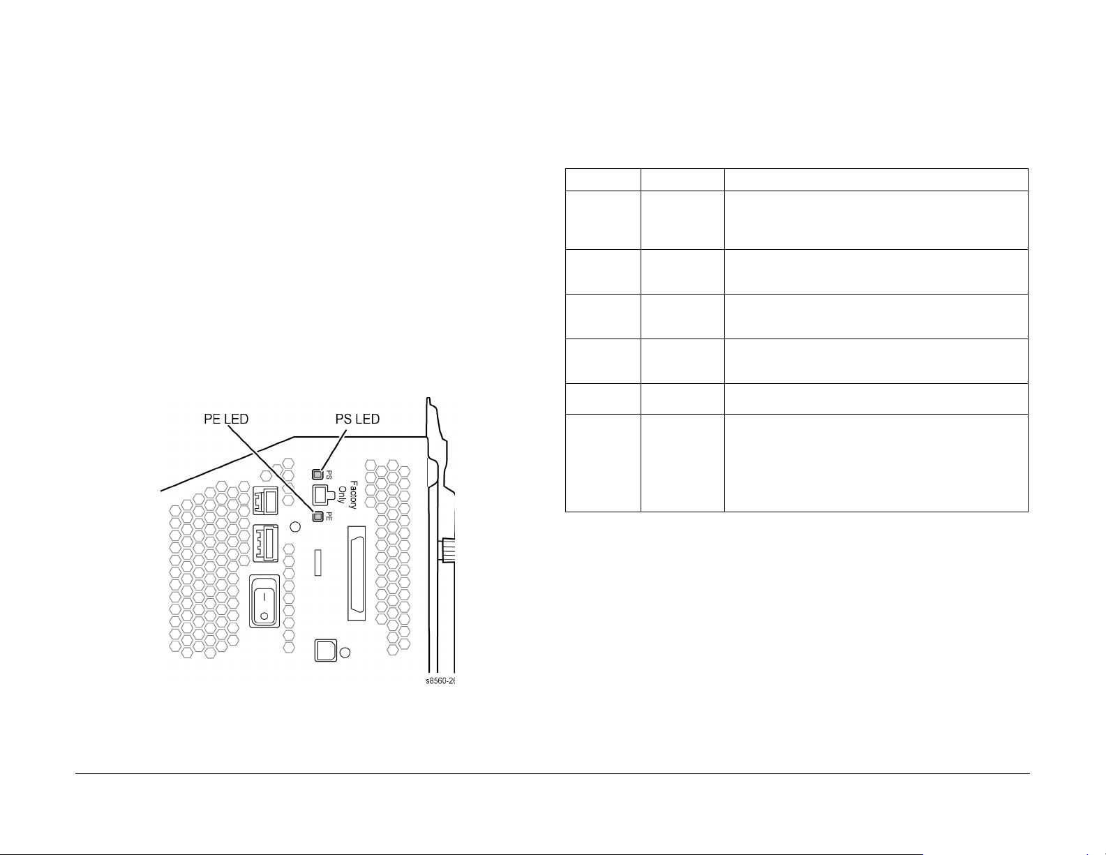
In addition to the numeric error codes appearing on the Control Panel display, the system uses
the Control Panel, PS, and PE LEDs to communicate errors. Figure 1 shows location of the PS
and PE LEDs on the Electronics Module.
BIST Error Reporting
BIST verifies basic Electronics Module CPU operation and reports failures using PS and PE
LEDs. These LEDs are located on the Electronics Module directly above the Scanner Assembly connection. BIST tests occur immediately at power-up, before POST tests are run or the
Control Panel is initialized.
The following table defines the blink patterns associated with a failure:
Table 1 BIST Blink Pattern Error Reporting
PE LED PS LED Description
Off or 1 blink,
then Off
On solid (dim) On solid (dim) Initialization failure. The system is held in reset mode. This
Off PS and Control
1 Rapid Blinking The CPU and/or PCI bus is not communicating. Reboot the
2 Rapid Blinking ROM not responding. Reboot the system, if the error still
3 Rapid Blinking System hangs during initialization
Off or 1 blink,
then Off
Panel blink at 1/
2 sec. intervals
The power supply could not remain regulated when DC
power was applied so it shut down. Follow the troubleshooting procedures for electrical shorts (see Electrical Troubleshooting) and check the power supply fuses.
can be caused by an Electronics Module fault or a +3.3 V
power supply failure. See Electrical Troubleshooting.
Boot loader memory test failure. Ensure the systems RAM is
properly seated and that the correct RAM type is installed.
system. If the error persists, replace the Electronics Module
(REP 5.0.5).
occurs, replace the Electronics Module (REP 5.0.5).
1. Unplug all connections to the Electronics Module.
2. Plug in the Power Cable.
3. Power on the system.
4. If the problem persists, reseat the RAM Modules.
5. Replace the Electronic Module (REP 5.0.5).
Figure 1 PS and PE LED Locations
Initial Issue
Phaser 8510/8560MFP Multifunction Product
POST Error Reporting
POST checks the communication paths within the Electronics Module and to other various system components
POST testing initializes the Control Panel, and in most cases if an error occurs, a text message
is displayed on the Control Panel along with an LED blink code flashing on all three LEDs
(Control Panel LED, PS LED and PE LED). If initialization of the Control Panel fails, POST
errors will still report using the LED blink patterns. The sum of the flashes equal the error code.
If the code has more than 5 flashes, there is a brief pause between each set of 5 flashes to
make them easier to count. After all flashes occur within the code, there is a long pause and
then the flash pattern repeats.
“Soft” POST errors, that do not prevent the system from powering up completely, are displayed
on the Control Panel for 5 seconds, and then the system continues through the remainder of
POST. There are no rear panel LED codes associated with soft errors. Most soft errors will
cause the system to print a Startup Page with the error message on it.
10/2006
2-3
Error Messages and Codes
Power On Self Tests
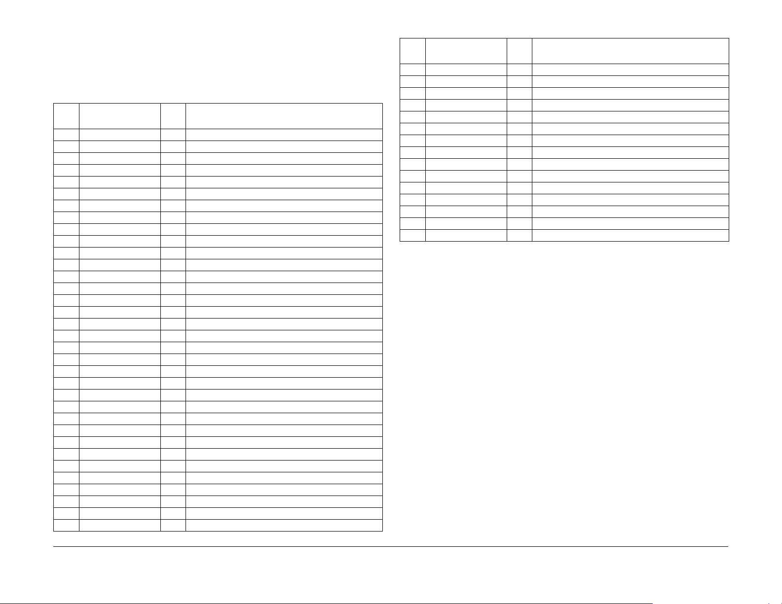
NOTE: Before replacing the Electronics Module for any POST errors, do the following:
1. Unplug all wiring and/or cables to the Electronics Module.
2. Plug in the AC power cable and power on the Electronics Module.
3. If the error blink pattern is now different from the original error reported before Step 1, the
problem may not be in the Electronics Module. See Electrical Troubleshooting.
Table 2 POST Blink Pattern Error Reporting
Error
PS, PE, and Control
Code
Panel LED s
01.01 Flutter then 01 blinks Hard Bad error code
02.01 Flutter then 02 blinks Hard Failed machine check
02.02 Flutter then 02 blinks Hard System panic
03.01 Flutter only Soft ID read failure
03.02 Flutter then 03 blinks Hard Mismatch
03.03 Flutter only Soft Version mismatch
03.04 Flutter then 03 blinks Hard Access failure
04.01 Flutter then 04 blinks Hard ID read failure
04.02 Flutter then 04 blinks Hard ID mismatch
04.03 Flutter then 04 blinks Hard TMVL mismatch, read/write failed
04.04 Flutter then 04 blinks Hard TMVL mismatch, read/write failed
05.01 Flutter then 05 blinks Hard I/O Board serial communication error.
05.02 Flutter only Soft I/O Board serial mismatch error.
6.08 No indication Soft Hard Drive failure
07.01 Flutter only Soft Control Panel communications error
07.02 Flutter only Soft Control Panel version mismatch
08.01 Flutter only Soft Control Panel failed to initialize
09.01 Flutter only Soft Control Panel data error
10.01 Flutter then 10 blinks Hard Power control link failure
10.02 Flutter only Soft Power control link invalid, mismatch error
11.01 Flutter then 11 blinks Hard EEPROM read failure
11.02 Flutter then 11 blinks Hard EEPROM write failure
11.03 Flutter then 11 blinks Hard EEPROM re-read failure
11.04 Flutter then 11 blinks Hard EEPROM data failure
12.nn Flutter only Soft Configuration Card failure
13.01 Flutter then 13 blinks Hard PHY reset failure (Low)
13.02 Flutter then 13 blinks Hard PHY ID error
14.nn Flutter then 14 blinks Hard USB ASIC error
15.01 Flutter then 15 blinks Hard CPU interrupt error
15.02 Flutter then 15 blinks Hard CPU interrupt error
15.03 Flutter then 15 blinks Hard CPU interrupt error, IRQ
15.04 Flutter then 15 blinks Hard CPU interrupt error
15.05 Flutter then 15 blinks Hard CPU interrupt error
15.06 Flutter then 15 blinks Hard CPU interrupt error
Error
Type Description
Table 2 POST Blink Pattern Error Reporting
Error
PS, PE, and Control
Code
Panel LED s
15.07 Flutter then 15 blinks Hard CPU interrupt error
15.08 Flutter then 15 blinks Hard CPU interrupt error
15.09 Flutter then 15 blinks Hard CPU interrupt error
15.10 Flutter then 15 blinks Hard CPU interrupt error
15.11 Flutter then 15 blinks Hard CPU interrupt error
16.01 Flutter only Soft Real Time Clock read failure
16.02 Flutter only Soft Real Time Clock write failure
16.03 Flutter only Soft Real Time Clock re-read failure
16.04 Flutter only Soft Real Time Clock failure
17.01 Flutter then 17 blinks Hard Insufficient RAM memory
18.01 Flutter then 18 blinks Hard IPCB ID read failure
18.02 Flutter then 18 blinks Hard IPCB ID mismatch
18.03 Flutter then 18 blinks Hard IPCB PCI configuration failure
18.04 Flutter only Soft IPCB version mismatch
19.01 Flutter then 19 blinks Hard Hard Drive failure
PEST Error Reporting
PEST tests occur after POST tests have been run and PostScript has been initialized. PEST
checks the connections and operation of various system components.
Error codes for PEST tests are displayed on the Control Panel and are all in the 37,XXX.xx
series. For troubleshooting PEST error codes, see Error Message Troubleshooting.
Error
Type Description
Error Messages and Codes
Power On Self Tests
10/2006
2-4
Initial Issue
Phaser 8510/8560MFP Multifunction Product

NVRAM Reset
Many of the troubleshooting procedures in this section include an NVRAM reset as a procedural step. Following an NVRAM reset, the system is unable to communicate on the network
and has lost several parameters specific to the customer’s configuration. If possible, print a
Configuration page to capture networking parameters. and discuss the customer’s configuration to document these settings before resetting NVRAM.
Table 1 lists the parameters reset by NVRAM Reset. Required parameters (Yes) must be configured to restore default system operation on the network.
Table 1 Parameters Reset with the Service Diagnostics NVRAM Reset Command
Menu Parameter Default Required
TCP/IP Setup TCP/IP On Yes
DHCP/BOOTP On Yes
AutoIP On Yes
TCP/IP Address 0.0.0.0 Yes
TCP/IP Network Mask 0.0.0.0 Yes
TCP/IP Gateway 0.0.0.0 Yes
Port 9100 On Yes
LPR On Yes
IPP On Yes
SLP On Yes
SSDP On Yes
CentreWare IS On Yes
Network Setup Ethernet Speed Auto Yes
EtherTalk On Yes
USB Setup USB Port On Yes
Wait Timeout (USB) 30 Yes
Page Description Language (USB) AutoSelect Yes
Control Panel Setup Control Panel Language English No
Control Panel Brightness 5 No
Control Panel Contrast 5 No
Accessible Control panel Off No
Copy Defaults Setup Color Mode Color No
2-Sided Copying 1-1 No
Output Quality Enhanced No
Document Type Mixed No
Paper Supply Tray 2 No
Color Balance -> Cyan Color Balance 0 No
Color Balance -> Magenta Color Balance 0 No
Color Balance -> Yellow Color Balance 0 No
Color Balance -> Black Color Balance 0 No
Laser Original Off No
Prescan Glass On No
Table 1 Parameters Reset with the Service Diagnostics NVRAM Reset Command
Menu Parameter Default Required
Copy Main Number of Copies 1 No
Paper Suppy Tray 2 No
Original Size Supply No
Prescan Glass On No
Preset Reduce/Enlarge None No
Collate Auto No
Edge Erase -> Left 0.0 No
Edge Erase -> Right 0.0 No
Edge Erase -> Top 0.0 No
Edge Erase -> Bottom 0.0 No
Margin Shift -> Long Edge 0.0 No
Margin Shift -> Short Edge 0.0 No
Auto Center Off No
Book Copy -> Both Pages ->Gutter Erase 0.0 No
Book Copy -> Left Page -> Gutter Erase 0.0 No
Book Copy -> Right Page -> Gutter Erase 0.0 No
Auto Suppression Off No
Covers -> Cover Tray Tray 1 No
Blank Separator Off No
Blank Separator Tray Tray 2 No
Create Booklet (8560MFP Only) Off No
Repeat Image (8560MFP Only) Off No
Repeat Image -> Rows 1 No
Repeat Image -> Columns 1 No
N-Up Off No
Poster Off No
Color Balance -> Cyan Color Balance 0 No
Color Balance -> Magenta Color Balance 0 No
Color Balance -> Yellow Color Balance 0 No
Color Balance -> Black Color Balance 0 No
Laser Original Off No
Fax Main Fax To None No
Resolution Standard No
Original Size Automatic No
Auto Suppression Off No
Transmission Report On No
Starting Rate Super G3 No
Initial Issue
Phaser 8510/8560MFP Multifunction Product
10/2006
2-5
Error Messages and Codes
NVRAM Reset
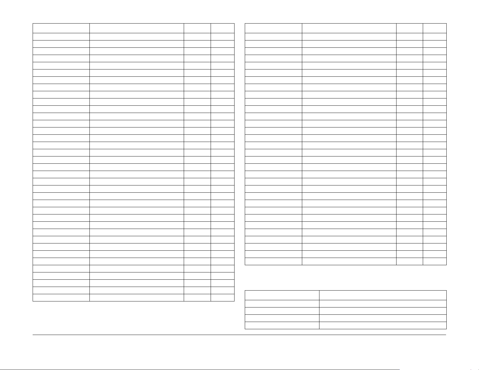
Table 1 Parameters Reset with the Service Diagnostics NVRAM Reset Command
Menu Parameter Default Required
Fax Send Setup Transmission Report Never No
Reduced Image (8560 only) Off Yes
Redial Count 3 No
Redial Time Interval 15 No
Auto Resend Policy Unsent Pg Yes
Auto Resend Count 3 Yes
Document Type Mixed No
Resolution Standard No
Transmission Header (8560 only) On No
Fax Receive Setup Paper Suplly Tray 2 Yes
Fax Receive On Yes
Answer Delay 0 Yes
Secure Receive (8560 only) Off Yes
Secure Receive Password (8560 only) None Yes
Junk Fax Prevention Off Yes
2-Sided Fax Printing 1-1 No
Fax Configuration Line Name None Yes
Dial Type Tone Yes
Line Monitor Volume 2 No
Auto Activity Report Off No
Starting Rate Super G3 Yes
Error Correction Mode On Yes
Fax Configuration Dial Pause 3 No
Dial Delay 0 No
Max Compression JBIG/MMR No
File Security Daily Removal Off Yes
Remove At 00:00 Yes
Age-based Removal Off Yes
Remove at Age 24 Yes
Paper Handing Setup Load Paper Timeout 3 min. No
Tray 1 Mode Dynamic No
Tray 1 Prompt 30 sec. No
Tray 2 ~ [N] Mode Dynamic No
Tray 2 ~ [N] Prompt None No
Letter/A4 Substitution On No
Custom Units Inches/mm No
Cleaning Page Source Highest No
Table 1 Parameters Reset with the Service Diagnostics NVRAM Reset Command
Menu Parameter Default Required
System Controls Startup Page On No
Auto Clear Timeout 60 sec. No
Power Saver Timeout 4 hours No
Date and Time None No
Intelligent Ready On No
Default Function Copy No
Color Copy Password Disabled No
Print Job Interrupt (8560 only) On No
Paper Tray Setup Tray 1 Paper - Media Size Guide Size No
Tray 1 Paper - Media Type Plain No
Tray 2 Paper - Media Type Plain No
Tray 3 Paper - Media Type (if installed) Plain No
Tray 4 Paper - Media Type (if installed) Plain No
Print Defaults Setup Paper Source Auto No
2-Sided Printing Disabled No
PS-PCL Setup Pitch 10.00 No
Point Size 12.00 No
Symbol Set PC8 No
Oreientation Portrait No
Form Length 6 No
Line Termination On No
Draft Mode Off No
Color Mode Color No
Scan Default Setup Color Mode Color No
Document Type Mixed No
Scan Resolution 100x100 No
Laser Original Off No
Scan Main Scan To Public No
Scan Resolution 100x100 No
Original Size Automatic No
Auto Suppression Off No
Laser Original Off No
Table 2 summarizes system parameters not affected by an NVRAM Reset.
Table 2 System Parameters Not Affected by an NVRAM Reset
Parameter Comment
Metric Defaults
MAC Address Set by the Configuration Card
Serial Number
Model number
Error Messages and Codes
NVRAM Reset
10/2006
2-6
Initial Issue
Phaser 8510/8560MFP Multifunction Product

Table 2 System Parameters Not Affected by an NVRAM Reset
Parameter Comment
License Number
PostScript Version
PostScript Revision
Activation Date The activation date is stored in Usage Profile NVRAM.
Adobe Serial Number
System Date and Time
Fax Country Fax Configuration
Fax Line ID Fax Configuration
Overwrite Removals File Security
Speed Dial Individual Directory Fax Send
Speed Dial Group Directory Fax Send
Tray Media Types and Sizes Unconfirmed following NVRAM Reset.
Metered Supplies Metered operation
Print Counter System Print Count
Billing Meters
Substituted Jets Jet Substitution Mode
Warm-up Mode Set in CWIS
Warm-up Settings Set in CWIS
Stand-by Settings Set in CWIS
Error Message Troubleshooting
This section covers troubleshooting procedures utilizing Control Panel error messages and
codes. Some procedures require running Service Diagnostic test functions to verify that a component is operating correctly. Procedures that direct a test to be run are referencing tests from
within the Hidden Service menu. For information on Service Diagnostics, see Service Diagnostics.
For troubleshooting problems not associate with an error code or message, such as startup or
power on, media, paper path, print-quality or image problems, and electrical failures, see General Troubleshooting.
Fault Code Error Reporting
Fault codes are saved to NVRAM and can be retrieved from the printer’s fault history.
In normal customer mode, the printer will reboot each time an error occurs. If three of the same
errors occur within 72 hours, or 1000 pages, the fault will be displayed on the printer’s Control
Panel.
Interpreting Fault Codes
• Failing system (XX,yyy.zz)
• Failing subsystem (xx,YYY.zz)
• Checksum (xx,yyy.zZ)
• Type of problem (xx,yyy.Zx)
• Print engine page count when the error occurred (xx,yyy.zz:123)
Device faults are indicated by a 4 in the tenths place of the fault code (xx,yyy.4x). This indicates
a hardware problem. The most common device faults troubleshooting procedures are documented in this section.
Initial Issue
Phaser 8510/8560MFP Multifunction Product
Program faults are indicated by a 6 in the tenths place of the fault code (xx,yyy.6x). Unfortunately, there are too many program faults to enumerate them all and most program faults will
not mean anything unless you are intimately familiar with the code base. Some of the more
common program faults are documented in this section.
CPU exceptions are indicated by a 7 in the tenths place of the fault code (xx,yyy.7z). The error
code indicates both the Power PC exception number and the region of firmware that was executing when the exception occurred: Engine, PostScript, Network, or Operating System.
NOTE: A CPU exception can either be caused by hardware or firmware error. Refer to the
infoSMART Knowledge Base for descriptions of the most common faults.
10/2006
2-7
NVRAM Reset, Error Message Troubleshooting
Error Messages and Codes
 Loading...