


 Loading...
Версия 22.05.2009
Руководство по техническому обслуживанию
PHASER 8400/8500/8550/8560
Документация изменена и дополнена:
1. Добавлены технические бюллетени для аппаратов Phaser 8400/8500/8550/8560.
Xerox
Office Service Bulletin 2-Feb-2004
Group
Phaser 8400 |
SB 607 |
|
Washer On The Drum Assembly’s Lower Right Mounting Screw May Cause Dog-earing On Prints
LOWER RIGHT DRUM SCREW USES NO WASHER
A washer added to the lower right screw that holds the Drum Assembly to the Chassis on the right side prevents the right Labyrinth Seal from seating in its proper location. This can cause the Stripper Carriage to also not be properly located. In very rare cases this results in prints on lighter-weight papers having one corner folded over on the leading edge (dog-ear) as they are stripped from the Drum. Occasional dog-earing is normal.
WHAT TO DO
When servicing a drum assembly ensure there is no washer on the lower right drum mounting screw. Update your service manual’s Drum Disassembly/Assembly Procedure indicating all the drummounting screws use washers except the lower right screw.
Phaser |
Xerox Office Group Service Bulletin |
SB 607 |
|
|
|
2.Retighten the rear screw to 25 in-lbs.
3.Tighten the lower screw (without washer) and torque to 25 inlbs.
4. Tighten the front screw to 25 in-lbs.
When troubleshooting a persistent dog-ear print problem, ensure the Stripper Carriage Assembly works correctly and the stripper blade is not damaged. Also ensure an appropriate paper is being used.
PARTS STRATEGY
Do not replace the Drum Assembly to correct a dog-ear print problem. Remount the assembly and ensure the screws are correctly installed and tightened.
TE
No washer
s8400-160a
The proper sequence for tightening the right-side drum screws is: 1. Loosen the three drum screws.
Service Manual Update SB607 SB 607 |
Page 1 of 2 |
|
Copyright © 2003 Xerox Corporation. All rights reserved. XEROX®, the stylized X®, and Phaser® |
Page 2 of 2 |
|
trademarks of Xerox Corporation in the United States and/or other countries. |
|
|

Xerox
Office Service Bulletin 16-Aug-2004
Group
Phaser 8400 |
SB 608, Rev 1 |
Some FRU part numbers are not orderable
SERVICE MANUAL LISTS FRU PART NUMBERS THAT CANNOT BE ORDERED BY THE FIELD ORGANIZATION
Four part numbers listed in the service manual cannot be ordered by the field organization. Alternate 650part numbers have been set up to use instead.
FRU Part |
Old (unusable) |
New part number you |
||
|
part number |
should order with |
||
525-Sheet Feeder |
097S03174 |
650-4331-00 |
||
(HCF) with Tray |
|
|
|
|
Main Tray |
097S03195 |
650-4332-00 |
||
|
|
|
||
|
|
|
|
|
Hard Drive Assy |
097S03172 |
|
650-4299-00 |
|
|
|
|
||
Hard Drive Assy with |
097S03173 |
650-4330-00 |
||
Japanese Fonts |
|
|
|
|
WHAT TO DO
Update your service manual with the new, replacement part numbers. Do not use the old part numbers to order an FRU.
PART INVENTORY STRATEGY
Do not stock these parts. Order them only when needed for a printer repair.
TME
Service Manual Update |
Rev 1 Page 1 of 1 |
Copyright © 2003 Xerox Corporation. All rights reserved. XEROX®, the stylized X®, and Phaser® trademarks of Xerox Corporation in the United States and/or other countries.
Xerox
Office Service Bulletin
Group
6-August-2004
Phaser 8400 SB624Rev2 SB 624 Rev3
SB 624 Rev 2
Printhead Exhibits Random Missing Jets
INFORMATION: SERIAL-NUMBERED PRINTERS RPC030017 TO RPC044425 REQUIRE PRINTHEAD FIRMWARE CODE UPDATE
Printhead engineering has developed new drift compensation algorithms that improve reliability of the Phaser 8400 printer’s printhead. All printers serial-numbered below RPC044426 need to have their printhead’s firmware updated via a downloadable snippet file. Printers RPC044426 and above already have the new algorithm built in.
The snippet file and a readme file are packaged as files 8400_fw_update.exe (PC) or 8400_fw_update.dmg (Mac). They are available at:
http://www.office.xerox.com/cgi-bin/formeng.pl?form=8400printheadfirmware
Follow the readme instructions to download the snippet to a printer.
About a year or so after the printer was manufactured, a printhead that is not updated will exhibit numerous, random missing jets. The missing jets may clear with a cleaning cycle but other jets drop out. Downloading the update file to the printer resolves this problem. There is no means to determine the printhead’s firmware version. Only downloading the snippet to the printer will tell you if the printhead firmware is up-to-date or not. Following the download, the printer prints a download status print.
WHAT TO DO |
|
|
As you service a Phaser 8400 printer, |
|
|
check its serial number. If it is between |
|
|
RPC030017 to RPC044425, download the |
|
|
printhead firmware update snippet to |
|
|
the printer. For update tracking |
|
|
purposes, indicate in your Tech Notes |
With an indelible marker, |
|
when you have updated a printer. Also |
||
mark the underside of the exit |
||
mark the underside of the exit door with |
door with a “PH” |
a “PH” to indicate the printer has been updated.
PART INVENTORY STRATEGY |
|
None. |
TME |
|
|
Firmware Issue |
Page 1 of 1 |
Copyright © 2003 Xerox Corporation. All rights reserved. XEROX®, the stylized X®, and Phaser® trademarks of Xerox Corporation in the United States and/or other countries.

Xerox
Office Service Bulletin 21-July-2004
Group
Phaser 8400 |
SB 633 |
|
EMI Suppression Changes SB633 633
NEWER PRINTERS FEATURE NEW EMI SUPPRESSION DEVICES
Newer printers may include new EMI countermeasures. These include:
•Choke coil on the left umbilical wiring harness
•Media path motor-to-drum motor bracket ground strap
•X-axis motor bracket-to-drum fan bracket ground strap
•X-axis motor bracket-to-chassis ground strap
•0-ohm Y-axis motor ground wire (replaces 100k ohm ground wire)
Choke coil
Braided cables
O-ohm ground wire
Service Manual Update |
Page 1 of 2 |
Copyright © 2003 Xerox Corporation. All rights reserved. XEROX®, the stylized X®, and Phaser® trademarks of Xerox Corporation in the United States and/or other countries.
Phaser |
Xerox Office Group Service Bulletin |
SB 633 |
|
|
|
WHAT TO DO
Ensure these EMI countermeasures are correctly re-installed when you service printers featuring these parts.
Older printers that do not feature these EMI countermeasures do not need to be updated.
Update your service manual with this information.
PART INVENTORY STRATEGY
None
TME
Page 2 of 2

SERVICE BULLETIN
Date Issued: 10 Oct 2006
SB 634 Rev 1
Product: Phaser 8400, 8500, 8550, C2424
Operational Groups: OPB, NADC
INSUFFICIENT AC POWER CAN CAUSE 37,002 THRU 37,013 PEST FAULT CODES
AC power supplied by power sources such as uninterruptible power supplies (UPSs) or DC-to-AC inverter systems may not supply correct voltage to properly power up the printer. Likewise, other devices sharing the same AC circuit can cause AC voltage sags that cause the printer to fail its AC heater PEST tests (Print Engine Self Test).
In both cases the printer may produce any of the following disconnected heater errors:
•Printhead jet-stack 37,002.47 or 37,003.48
•Reservoir heater, 37,004.40 or 37,005.41
•Drum heater error 37,006.42
•Preheater error 37,008.44
•Ink melters errors 37,009.45 thru 37,013.40
SOLUTION
Verify the AC power source when you troubleshoot a printer exhibiting any of these errors. Try powering up the printer on a different AC circuit on a different breaker. Turn off other devices, such as laser printers and coffee makers on the same circuit.
PART INVENTORY STRATEGY
None.
TME
Pub. No.:
CAUSE
The printer features several heaters controlled by printer electronics and powered by AC electricity. The printer itself can power up despite insufficient or irregular AC voltage but it may fail its AC heater tests. This is due the test not measuring sufficient current flowing through the heater at the moment the test runs.
Devices sharing the AC circuit shared with the printer, such as a laser printer pulse-heating its fuser, a coffee maker heating its warming plate via a thermo-breaker, or a space heater turning on, may be placing heavy intermittent demand on the AC circuit. This sudden inductive demand creates momentary AC voltage sag that causes the PEST test to fail.
Copyright © 2006 Xerox Corporation. All rights reserved. XEROX®, the stylized X®, and Phaser® |
1 of 1 |
|
|
trademarks of Xerox Corporation in the United States and/or other countries. |
|

Xerox
Office Service Bulletin 21-July-2004
Group
Phaser 8400 |
SB 635 |
|
SB635 635
Undocumented Error Codes 11,001 thru 11,100
UNDOCUMENTED/CORRECTED ERROR CODES
|
11,001.47 - |
Upper feeder –Tray 2 – broken serial communication timeout |
|
ECM_UHCF_SER_LINK_ |
failure detected. Seven consecutive frames occurred with |
|
BROKEN |
errors. Ensure the ground integrity of the printer. Inspect |
|
|
and reseat all connectors. Reset NVRAM and retest. |
|
11,002.41 - |
Lower feeder –Tray 3 – broken serial communication timeout |
|
ECM_LHCF_SER_LINK_ |
failure detected. Seven consecutive frames occurred with |
|
BROKEN |
errors. Ensure the ground integrity of the printer. Inspect |
|
|
and reseat all connectors. Reset NVRAM and retest. |
|
|
Replace the Tray 3 feeder assembly. |
|
11,003.42 - |
Front panel broken serial communication timeout failure |
|
ECM_FP_SER_LINK_ |
detected. Seven consecutive frames occurred with errors. |
|
BROKEN |
Ensure the ground integrity of the printer. Inspect and reseat |
|
|
all connectors. Reset NVRAM and retest. Replace the front |
|
|
panel. |
|
11,004.43 - |
I/O board broken serial communication timeout failure |
|
ECM_IO_SER_LINK_ |
detected. Seven consecutive frames occurred with errors. |
|
BROKEN |
Ensure the ground integrity of the printer. Inspect and reseat |
|
|
all connectors. Reset NVRAM and retest. Replace the I/O |
|
|
board. |
|
11,005.44 - |
Power control board broken serial communication timeout |
|
ECM_PCTL_SER_LINK_ |
failure detected. Seven consecutive frames occurred with |
|
BROKEN |
errors. Ensure the ground integrity of the printer. Inspect |
|
|
and reseat all connectors. Reset NVRAM and retest. |
|
|
Replace the electronics module. |
|
11,006.45 - |
Printhead broken serial communication timeout failure |
|
ECM_HEAD_SER_LINK_ |
detected. Seven consecutive frames occurred with errors. |
|
BROKEN |
Ensure the ground integrity of the printer. Inspect and reseat |
|
|
all connectors. Reset NVRAM and retest. Replace the |
|
|
printhead |
|
11,007.44 - |
A PCI anomaly or PCI core bit error occurred. Ensure the |
|
ECM_PCI_ERROR |
ground integrity of the printer. Inspect and reseat all |
|
|
connectors. Reset NVRAM and retest. Replace the |
|
|
electronics module |
|
11,008.45 - |
A DMA transfer error was detected. Ensure the ground |
|
ECM_DMA_TRANSFER_ |
integrity of the printer. Inspect and reseat all connectors. |
|
FAILURE |
Reset NVRAM and retest. Replace the electronics module. |
|
11,009.46 - |
PostScript communication timeout failure detected. This |
|
|
indicates the PS microcontroller received no response for |
|
|
|
|
Service Manual Update |
Page 1 of 2 |
Copyright © 2003 Xerox Corporation. All rights reserved. XEROX®, the stylized X®, and Phaser® trademarks of Xerox Corporation in the United States and/or other countries.
|
Phaser |
Xerox Office Group Service Bulletin |
SB 635 |
|
|
|
|
||
|
|
|
||
|
ECM_PS_COM_FAILURE |
800ms. Ensure the ground integrity of the printer. Inspect |
||
|
|
|
and reseat all connectors. Reset NVRAM and retest. |
|
|
|
|
Replace the electronics module. |
|
|
11,010.48 - |
|
PS hardware version mismatch. This indicates that the PS |
|
|
ECM_PS_HW_VERSION_ |
hardware does not match the expected version. Replace the |
||
|
MISMATCH |
|
electronics module. |
|
|
11,011.48 - |
|
PS software version mismatch. This indicates that the PS |
|
|
ECM_PS_SW_VERSION_ |
software does not match the expected version. Replace the |
||
|
MISMATCH |
|
electronics module. |
|
|
11,010.47 - |
|
PS hardware version mismatch. This indicates that the |
|
|
ECM_PS_HW_VERSION_ |
PostScript hardware does not match the expected version. |
||
|
MISMATCH |
|
Replace the electronics module. |
|
|
11,012.49 - |
|
Power Control PLD version mismatch. This indicates that the |
|
|
ECM_PCTL_PLD_ |
|
power control programmable logic device does not match the |
|
|
VERSION_MISMATCH |
|
expected version. Replace the electronics module. |
|
|
11,013.41 - |
|
I/O PLD version mismatch. This indicates that the I/O |
|
|
ECM_IO_PLD_VERSION_ |
programmable logic device does not match the expected |
||
|
MISMATCH |
|
version. Replace the I/O board. |
|
|
11,014.42 - |
|
Front panel version mismatch. This indicates that the front |
|
|
ECM_FP_PLD_VERSION |
panel programmable logic device does not match the |
|
|
|
MISMATCH |
|
expected version. Replace the front panel. |
|
|
11,015.43 - |
|
Head PLD version mismatch. This indicates that the Head |
|
|
ECM_HEAD_PLD_ |
|
programmable logic device does not match the expected |
|
|
VERSION_MISMATCH |
|
version. Replace the printhead. |
|
|
11,016.44 - |
|
Bottom HCF programmable logic device version mismatch. |
|
|
ECM_BTM_HCF_PLD_ |
|
This indicates that the bottom HCF programmable logic |
|
|
VERSION_MISMATCH |
|
device does not match the expected version. Replace the |
|
|
|
|
Tray 3 feeder assembly. |
|
|
11,017.45 - |
|
Top HCF PLD version mismatch. This indicates that the top |
|
|
ECM_TOP_HCF_PLD_ |
|
HCF programmable logic device does not match the |
|
|
VERSION_MISMATCH |
|
expected version. Replace the Tray 2 feeder assembly |
|
|
11,018.46 - |
|
Titan version mismatch. This indicates that Titan chip does |
|
|
ECM_TITAN_VERSION_ |
not match the expected version. Replace the electronics |
||
|
MISMATCH |
|
module. |
|
|
11,100.60 - |
|
Generally, the root problem for this error is temperature |
|
|
ECM: PS UC FOUND A |
|
sensitivity with the power-supply’s opto-isolator chips. |
|
|
PARITY ERROR WITH |
|
Replace the electronics module. |
|
|
THE LAST ECM XMIT |
|
|
|
WHAT TO DO
Update your service manual with this information.
PART INVENTORY STRATEGY
None
TME
Page 2 of 2

Xerox
Office Service Bulletin 27-July-2004
Group
Phaser 8400 |
SB 636 |
|
Troubleshooting the 37,016 Error Code SB636 636
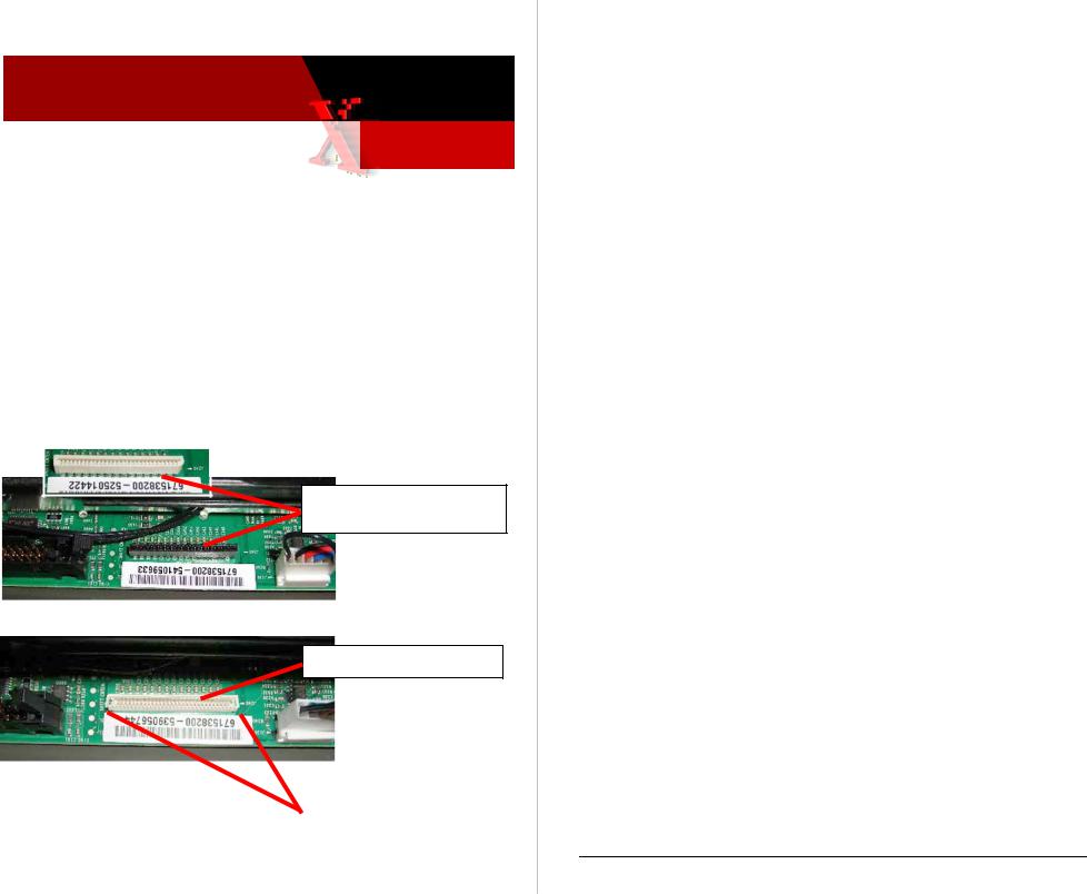
TECHNIQUES FOR TROUBLESHOOTING THE 50V POWER SUPPLY FAULT ERROR CODE
37,016.4x - PEST_FAULT_HM_CLUTCH_DISCONNECT
Despite the “clutch disconnect” message, this error code indicates that the 50V power supply failed its PEST test. (The 50V supply is loaded with the head maintenance wiper clutch in order to test; hence the message when the test fails.) Follow these steps in the order listed to find a short that is causing the 50v supply to fail:
1.Checking for a short in electronics module. Turn off the printer and wait 30 seconds for power supply capacitors to discharge. Damage to circuits within the electronics module may occur if the power supply capacitors are not allowed to fully discharge.
NOTE: It is possible that the power supply is not shorted but instead is out of spec, which leads to an error condition. You can measure the 50V power supply output. The test point is located on the Power Control board below the main board’s RAM DIMMs.
50v power supply test point
Typically, the power supply should measure 50v (47 to 52v).
Service Manual Update |
Page 1 of 4 |
Copyright © 2003 Xerox Corporation. All rights reserved. XEROX®, the stylized X®, and Phaser® trademarks of Xerox Corporation in the United States and/or other countries.
Phaser 8400 |
Xerox Office Group Service Bulletin |
SB 636 |
|
|
|
2.Unplug the following electronics module connectors. This step disconnects all other external circuits so the electronics module can be tested alone:
•Power Control to I/O board (J800 - gray ribbon cable on right side)
•Power Control right (J400 – 16 wire, multi-color)
•Printhead data interface (J130 – gray ribbon cable on top side)
•Wave amp signal (J790) short gray ribbon cable located on left side)
•Power Control left (J390 – 34 wire, multi-color)
•Y-Axis motor (J280)
3.Turn on power to the printer.
4.If the PE and PS indicators do not flash, the short is inside the electronics module. Replace the electronics module and retest the printer. If PE and PS indicators flash, continue with the next step.
5.Checking for short on the I/O board. Turn off the printer and wait 30 seconds for power supply capacitors to discharge.
6.Unplug the front panel connector (J220) on the I/O board. This removes the front panel from the I/O board.
7.Plug in the Power Control to I/O board connector (J800). This step adds the I/O board back to the working electronics module - nothing else is connected.
8.Turn on power to the printer. If the PE and PS indicators do not flash, the short is on the I/O board or related cabling.
If the 50V PS LED (viewed thru the cooling grill below the power cord receptacle) illuminates, the short is on one of the external devices you unplugged earlier. In this case, systematically turn off the printer, plug a wiring harness back in, and turn the printer on until the 50V supply fails.
9.Turn off the printer. Verify the short is on the I/O board by using an ohmmeter to check the resistance on I/O board J270, pin 1 to ground. Resistance of less than 1K ohm indicates a problem.
10.To isolate the problem to the I/O board or its related cabling, unplug the I/O board connectors. Leave the control panel (J220) plugged in:
•Umbilical Right J1
•Waste Tray Sense J110
•Stripper Solenoid J250
•Paper Tray Sense J610
Page 2 of 4

Phaser 8400 |
Xerox Office Group Service Bulletin |
SB 636 |
|
|
|
•Front Door Sense J600
•Ink load Signal J910
•DMU Sense J860
•Drum Thermistor J870
•Exit Module J680
•Heater Relay Control J950
11.Retest the resistance of the I/O board. If the resistance is still less than 1K ohm, replace the I/O board, reinstall all cables and retest printer. If the I/O board resistance is not shorted, plug in the I/O board connectors one at a time and retest the resistance. Replace the component that creates a short at J270.
12.Turn on the printer.
13.If the PE and PS indicators do not flash, the short is on the front panel. Replace the front panel and retest the printer.
14.Checking for a short circuit on 50V within the printhead. Turn off printer and wait 30 seconds for power supply capacitors to discharge.
15.Plug in the printhead interface connector (J130) to the electronics module. This step adds the printhead back to a working electronics module and I/O board.
16.Turn on power to the printer.
17.If the PE and PS indicators do not flash, the short is on the printhead. Replace the printhead and retest the printer. Test the printer to ensure damage to the electronics module did not occur due to the shorted printhead.
18.Run the Head Maintenance Clutch test.
19.Check the Head Maintenance Clutch wiring.
20.Connect the Wave Amp signal cable (J790) at the left side of the Electronics Module.
21.Turn on power to the printer. If the PE and PS indicators do not flash, the short is on the wave amp. Replace the wave amp.
22.Reinstall all printer cables.
23.Test the printer.
Page 3 of 4
Phaser 8400 |
Xerox Office Group Service Bulletin |
SB 636 |
|
|
|
WHAT TO DO
Update your service manual with this information.
PART INVENTORY STRATEGY
None
TME
Page 4 of 4

Xerox
Office Service Bulletin 3-Aug-2004
Group
Phaser 8400 |
SB 637 |
|
Troubleshooting Dead or Hung Printers SB637 637
Techniques For Troubleshooting Printers That Are Hung At Power-Up Or Appear Dead
Dead or hung printers can fail to power-up for a variety of reasons ranging from improper AC power source to defective components. The following steps can help resolve dead or hung printers:
1.Verify the printer is in a hung condition
2.Eliminate corrupted data in the printer’s memory
3.Isolate the printer from the network
4.Isolate the hard drive (if installed)
5.Verify the power source
Verify The Printer Is Hung
The printer can take several minutes to reach its operating temperature. Cold environments require more time. If the printer appears to be hung (unable to respond), open the front cover.
•If the front panel message changes from “Warming Up” to “Close Front Cover to Continue”, the printer is not hung. Instead, it may be in the process of warming up, canceling a large job, or even processing a job.
•If the front panel message does not change after opening the front cover, the printer is hung (unable to respond).
Eliminate Corrupted Data From Memory
If there is corrupted data in the printer’s memory, the printer may be unable to generate embedded pages. Use the following procedure to eliminate the corrupted data:
Service Manual Update |
Page 1 of 4 |
Copyright © 2003 Xerox Corporation. All rights reserved. XEROX®, the stylized X®, and Phaser® trademarks of Xerox Corporation in the United States and/or other countries.
Phaser 8400 |
Xerox Office Group Service Bulletin |
SB 637 |
|
|
|
1.Turn off the printer. Wait for it to completely shut down. Unplug the printer’s AC power cord.
2.After at least 30 seconds, reconnect the power cord and turn on the printer.
•If the printer powers-up correctly, try printing the
Configuration Page or Startup Page (or any embedded page). If the embedded pages print normally, the problem has been solved.
•If the printer does not power-up correctly, go to the next procedure.
Isolating Network Issues
Corrupted network traffic, print files, or printer drivers can cause the printer to hang. Use the following procedure to isolate the printer from the network:
1.Disconnect all communication cables from the printer, power down the printer for 30 seconds, and then turn on the printer.
•If the printer does power-up, try printing an embedded page such as the Configuration page or Startup.
•If the embedded pages do not print, there may be corrupted data in the printer’s RAM. Complete the procedure “Eliminate Corrupted Data from RAM”.
•If the embedded pages print normally, go to Step 2.
•If the printer does not power-up correctly, proceed to the “Isolate the Hard Drive” topic.
2.Try printing an embedded page when the printer is connected to the network.
•If the embedded pages print normally, go to Step 3.
•If the printer stops responding while connected to the network, there may be corrupt network information getting to the printer.
3.Send a print job to the printer using the network connection. If the printer stops responding only after sending the print job, the file or printer driver may be corrupted. Try to isolate the file and/or reinstall the printer driver. Reviewing the printer's Network Logs
(front panel Troubleshooting menu > Network Log Pages) can offer clues to a network event that might be confusing the printer.
Page 2 of 4
Phaser 8400 |
Xerox Office Group Service Bulletin |
SB 637 |
|
|
|
Isolate the Hard Drive (if installed)
If the printer is a DX model equipped with a hard drive, corrupted files on the hard drive may prevent the printer from completing its start-up sequence. Use the following procedure to isolate problems to the hard drive. Observe ESD precautions:
1.Turn the printer off.
2.At the rear of the printer, open the access panel (held in place with two thumbscrews). The hard drive mounts to the access panel.
3.Disconnect the wide, gray data cable from the Hard Drive Assembly.
4.Turn on the printer.
•If the printer powers on normally, the hard drive must be replaced.
•If the printer fails to power on go on to the next procedure.
Verify the Power Source
Verify the printer is plugged into a stable power source that can supply enough current for the printer’s initial warm-up. Always plug the printer directly into a known-to-be-good outlet. If other devices are plugged into the same circuit, there may not be enough power available for the printer.
The printer can tolerate AC power level fluxuations (brown-outs). But it cannot tolerate loss of AC cycles (blips, interruptions) or AC frequency changes. Also, the printer power must be a standard sinewave waveform.
Note: Many DC-to-AC inverter systems, gas-powered AC generators, and uninterruptible power supply devices do not output proper sinewave-shaped AC power. This makes them unsuitable as power sources for the printer. Likewise, many of those devices cannot output the current necessary to power the printer.
If the printer is unable to power on, use the following procedure to verify the power source:
1.Disconnect the printer from the suspect outlet.
2.Plug the printer directly into a stable, known-to-be-good wall outlet. If possible, monitor the line voltage. For testing purposes, do not use any of the following:
•Power strip/surge protector
•Uninterruptible power supply (UPS)
Page 3 of 4
Phaser 8400 |
Xerox Office Group Service Bulletin |
SB 637 |
|
|
|
•Circuits that connect to several other devices.
If the power-up problem only occurs when the printer is plugged into a surge protector, power strip, UPS, or one specific outlet, then the problem is with that device or outlet.
3.Verify that both ends of the power cord are firmly plugged in.
4.Turn on the printer.
•If the printer powers on normally, the problem has been solved.
•If the printer does not power on, go to Step 5.
5.Did the printer start power cycling (turning off and on) after a power surge from an electrical storm or power outage?
•If yes, turn the printer off and unplug it. After waiting at least 2 hours, plug the printer into a stable, known-to-be-good wall outlet and turn it on.
•If no, complete the next procedures found in the printer Service Manual.
6.Check for illuminated LEDs on the printer’s power supply. Refer to Service Manual topic “Verifying Power Supply Operation” for locations of the LEDs. Refer to Service Manual topic "Printer Fails to Power-Up: PS, PE and the 3.3 V Indicator LEDs are Not Illuminated" for troubleshooting instructions.
WHAT TO DO
Update your service manual with this information.
PART INVENTORY STRATEGY
None
TME
Page 4 of 4

Xerox
Office Service Bulletin 20-Aug-2004
Group
Phaser 8400, 8200, 860, 850 |
SB 640 |
|
JetFix Snippets Available To
Correct Weak And Missing Jets SB640 640
DOWNLOADABLE SNIPPETS EFFECTIVE FOR CLEARING WEAK OR MISSING PRINTHEAD JETS
A technique, referred to as JetFix, has been developed that is effective in clearing stubborn weak or missing jets that a printer’s regular printhead purge cycle cannot clear. The technique consists of raising the printhead drive voltage to 255, printing several solid fills of the missing jet color, returning the drive setting to its default 128 setting, and then performing a printhead clean/purge cycle. The technique is effective about 50% of the time in clearing a stubborn weak or missing jet.
This technique has been encapsulated into two sets of downloadable snippet files to simplify performing the technique. One set of files is for the Phaser 8400. The other set is for the 8200, 860 and 850. (The technique is not very effective in the Phaser 840 because of the age of the printheads).
Each set consists of four snippets; one for each ink color. When a printer receives a JetFix snippet it will print five double-coverage solid fills and then perform a printhead clean/purge cycle.
Note: It is normal for the solid-fill prints to show many light stripes; this will clear with the purge cycle.
If process should be interrupted by a power glitch or a hang, powerdown the printer, wait 30 seconds, and turn on the printer. The 255 Head Adjust setting automatically will be overwritten by the 128 value retrieved from the printer’s NVRAM on power-up.
Information |
Page 1 of 2 |
Copyright © 2004 Xerox Corporation. All rights reserved. XEROX®, the stylized X®, and Phaser® trademarks of Xerox Corporation in the United States and/or other countries.
Phaser 850, 860, 8200, 8400 Xerox Office Group Service Bulletin |
SB 640 |
|
|
WHAT TO DO
Before replacing a printhead for a weak or missing jet issue (not caused by non-Xerox ink) upload the appropriate JetFix snippet to the printer. Use the snippet that corresponds to the jet’s missing color. JetFix is effective in clearing printheads with one or two missing jets that cannot be cleared using the printer’s “Eliminate Light Stripes” cleaning cycles.
Obtain the snippets from the Customer Support Resources website: http://www.office.xerox.com/partners. Select 8400 from the Printer Info pulldown to retrieve the 8400’s snippets. Select 8200 or 860 from the Printer Info pulldown for the 8200/860/850 snippets.
A readme file is included with instructions on different methods of uploading a snippet to a printer.
Important Note: Always follow and complete the latest version of the
Troubleshooting Printhead Checklist. Be sure to include sample prints as noted in the checklist. Also be sure to correctly complete the green card.
PART INVENTORY STRATEGY
None
TME
Page 2 of 2

Xerox
Office Service Bulletin
Group
29 June 2005
|
|
|
|
SB 647 Rev 1 |
Phaser 8400, |
WorkCentre C2424, |
|
||
|
|
|||
Phaser 8500/8550 |
|
|
|
|
Camshafts Incorrectly Illustrated
In Service Manual
INFORMATION
The illustration on page 9-6 of the Service Manuals incorrectly shows the Drum Maintenance Camshaft and Transfix Camshaft assemblies. The camshaft drawings are transposed. Items highlighted in yellow indicate updates to original bulletin.
WHAT TO DO
Item 11 should point to the Drum Maintenance Camshaft (which has a gear at each end of the shaft). Item 10 should point to the Transfix Camshaft (it has no gear on its left end). The Drum Maintenance Camshaft should be located below the Transfix Camshaft. Modify your Service Manual similar to the following illustration.
PART INVENTORY STRATEGY
N/A |
JMK |
|
|
Service Manual Update |
Page 1 of 1 |
Copyright © 2004 Xerox Corporation. All rights reserved. XEROX®, the stylized X®, and Phaser® trademarks of Xerox Corporation in the United States and/or other countries.

Xerox
Office Service Bulletin 8-Dec 2004
Group
Phaser 8400 SB655 SB 655 sb655 sb 655 |
SB 655 |
|
Paper Path Motor Cooling Fan deleted, Left Side Power Control Harness and Exit Module Assembly modified
INFORMATION
The Paper Path Motor Cooling Fan is no longer installed on printers serial-numbered RCP148641 and above. The Left Side Power Control Wiring Harness has been modified to remove the fan’s receptacle and to include a resistor to simulate the presence of the fan to the printer’s boot up firmware. The exit module assembly has been modified to remove the motor cooling fan.
Ongoing reliability testing has determined that the motor cooling fan is not necessary. Therefore it is being removed for the remaining printers being built.
WHAT TO DO
Update you service manual with these new part numbers:
Paper Path Motor Cooling Fan |
No longer available |
Exit Module Assembly |
441-2239-81 |
Cable, Power Control Left Side |
174-4494-81 |
Parts Issue/Service Manual Update |
Page 1 of 2 |
Copyright © 2004 Xerox Corporation. All rights reserved. XEROX®, the stylized X®, and Phaser® trademarks of Xerox Corporation in the United States and/or other countries.
Phaser 8400 |
Xerox Office Group Service Bulletin |
SB 655 |
|
|
|
Service tips:
If a motor cooling fan has failed, remove it and replace the Left Side Power Control Wiring Harness with the new -81 version harness.
If you replace the exit module assembly, move the motor cooling fan from the old exit module assembly to the new assembly.
If you replace an old Left Side Power Control Wiring Harness (which does not have a paper path cooling fan plug receptacle), remove the paper path motor cooling fan.
The printer will produce the power-on error code 37,015.42 FAULT MP MOTOR DISCONNECT if the printer boots up with an old Left Side Power Control Wiring Harness but no Paper Path Cooling Fan.
PART INVENTORY STRATEGY
Do not stock these parts. Order them only when needed for a printer repair.
TME
Page 2 of 2

Xerox
Office Service Bulletin 06 Sept 2005
Group
Phaser 8400 |
SB 657 Rev 2 |
|
Ripping sound during transfixing; prints show poor transfix print quality
PIVOT PLATES CRACKING RESULTS IN INSUFFICIENT DRUM OILING
Cracking of the drum maintenance pivot plate results in the pivot plate not pushing the drum maintenance unit forward enough to provide sufficient oiling of the imaging drum during a print cycle. The result is poor ink transfixing and poor print quality.
The pivot plate may crack at either the left end or the right end or both. This results in a print quality defect, such as dropout or smear, at the corresponding left or right sides of the prints.
WHAT TO DO
Replace the original (white) pivot plate with the new (black) pivot plate.
Hardware Issue |
Page 1 of 2 |
Copyright © 2004 Xerox Corporation. All rights reserved. XEROX®, the stylized X®, and Phaser® trademarks of Xerox Corporation in the United States and/or other countries.
Phaser 8400 |
Xerox Office Group Service Bulletin |
SB 657 Rev 2 |
|
|
|
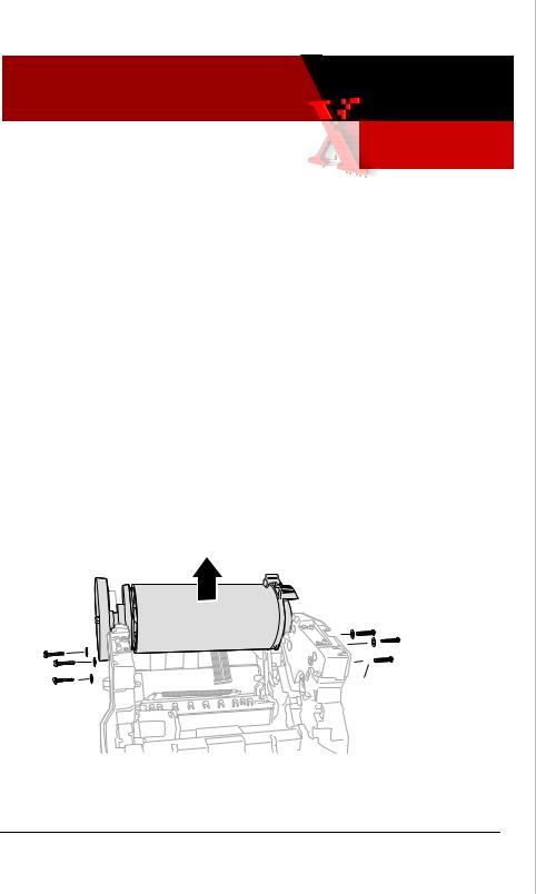
To replace the pivot plate:
1.Power-down the printer.
2.Remove the drum maintenance kit.
3.Remove the left and right side covers.
4.Unplug the pivot plate wiring harness from I/O board J860.
5.Remove the ground clip (lower-left corner of drum fan) from the right end of the drum maintenance shaft.
6.Remove the KL-clips securing each end of the drum maintenance shaft. Slide the shaft out of the printer frame.
7.Remove the pivot plate thru the drum maintenance kit cavity.
Observe standard ESD
Wiring harness precautions routes thru hole
Shaft
Pivot Plate
Lightly grease the metal plates on which the drum maintenance cams ride, using a small amount of Rheolube 768 grease (P/N 006- 7997-00). Also fill the pocket under the shaft ground with grease. Reverse the removal steps to install the new pivot plate.
Tip It you have difficulty seating the left end of the shaft thru the left side frame; remove the paper preheater for better access to the left end of the shaft and the pivot plate. Use needle-nose pliers to fish the wiring harness thru the right-side frame hole.
PART INVENTORY STRATEGY
Order this part as needed, and keep no more than one in trunk stock.
TME
Page 2 of 2

Xerox
Office Service Bulletin 21 Sept 2005
Group
Phaser 8550/8500 |
SB 700 |
|
Service Manual Corrections
INFORMATION
The tables below list errors, corrections and omissions in the Phaser 8400/8500/8550 Service Manual.
Table 1 Replaceable Parts List Changes
|
Page |
|
Item or Wording was: |
Correction or Change is: |
|
|||||||||
# |
|
|
|
|
|
|
|
|
|
|
|
|
|
|
9-5 |
|
Drum Maintenance Door |
|
Drum Maintenance Door (Side) |
|
|||||||||
|
|
|
|
(Side) 802K93870 |
|
802E |
|
93870 |
|
|
|
|||
|
|
|
|
|
|
|
|
|
|
|
|
|||
9-6 |
|
Illustrations of items 10 and |
|
Item 11has a gear on each end |
|
|||||||||
|
|
|
|
11 are swapped. |
|
of the camshaft. Item 10 only |
|
|||||||
|
|
|
|
|
|
|
|
has a gear on the right end |
|
|||||
9-7 |
|
Ink Loader Assy and Door |
|
Ink Loader Assy and Door |
|
|||||||||
|
|
|
|
133K25030 |
|
133K25031 |
(8500/8550) |
|
||||||
|
|
|
|
|
|
|
|
Ink Loader Assy and Door, |
|
|||||
|
|
|
|
|
|
|
|
PagePack 133K25660 (8550M) |
|
|||||
9-7 |
|
Printhead Wiper Assembly |
367053480 (8400/8500/8550) |
|
||||||||||
|
|
|
|
8500/8550 require ver. 4.302 |
|
033E05080 |
(8500/8550) |
|
||||||
|
|
|
|
firmware |
|
|
|
|
|
|
|
|
||
9-7 |
|
Belt, Wiper Drive |
214501280 (8400/8500/8550) |
|
||||||||||
|
|
|
|
8500/8550 require ver. 4.302 |
|
023E30660 |
(8500/8550) |
|
||||||
|
|
|
|
firmware |
|
|
|
|
|
|
|
|
||
|
9-7 |
|
|
Purge Pressure Pump |
|
|
Purge Pressure Pump |
|
|
|||||
|
|
|
|
604K31120 |
|
|
|
119641180 |
|
|
|
|
||
|
|
|
|
|
|
|||||||||
9-7 |
|
Transfix Camshaft Assy |
|
Transfix Camshaft Assy |
|
|||||||||
|
|
|
|
068K02160 |
|
008K02160 |
|
|
|
|||||
9-7 |
|
Transfix Roller |
|
Transfix Roller |
|
|||||||||
|
|
|
401102780 (8400) |
|
401102780 (8400) |
|
|
|||||||
|
|
|
|
022E32280 (8500/8550) |
|
022E32290 |
(8400/8500/8550) |
|
||||||
9-7 |
|
Drum Maintenance Pivot |
|
Drum Maintenance Pivot Plate |
|
|||||||||
|
|
|
|
Plate Assy 367053180 |
|
Assy 367053181 |
|
|||||||
|
|
|
|
|
|
|
|
|
|
|
|
|
|
|
Service Manual Update |
|
|
|
|
|
|
Page 1 of 4 |
|||||||
Copyright © 2004 Xerox Corporation. All rights reserved. XEROX®, the stylized X®, and Phaser® trademarks of Xerox Corporation in the United States and/or other countries.
|
|
Phaser 8500-8550 |
Xerox Office Group Service Bulletin |
SB 700 |
|||||
|
|
|
|
|
|
|
|
||
|
|
9-9 |
|
|
|
|
|
||
|
Outer Duplex Paper Guide |
|
Outer Duplex Paper Guide with |
|
|||||
|
|
9-9 |
with Sensors 351113681 |
|
Sensors 351113680 |
|
|
||
|
|
525-Sheet Feeder and Tray |
|
525-Sheet Feeder and Tray |
|
|
|||
|
|
9-11 |
059K50030 |
|
|
650-4331-00 |
|
|
|
|
|
Gearbox Media Drive with 2 |
|
Gearbox Media Drive with 2 |
|
|
|||
|
|
9-13 |
Clutches 807K16050 |
|
Clutches 807E16050 |
|
|
||
|
|
128 MB SDRAM 156486100 |
|
128 MB SDRAM 156483700 (8400) |
|
||||
|
|
|
(8400) |
|
|
256 MB SDRAM 156466300 (8400) |
|
||
|
|
|
256 MB SDRAM 156466300 |
|
128 MB SDRAM 856000200 |
|
|
||
|
|
|
(8400) |
|
|
(8500/8550) |
|
|
|
|
|
|
128 MB SDRAM 537E66480 |
|
256 MB SDRAM 856000300 |
|
|
||
|
|
|
(8500/8550) |
|
|
(8500/8550) |
|
|
|
|
|
|
256 MB SDRAM 537E66490 |
|
512 MB SDRAM 856000400 |
|
|
||
|
|
|
(8500/8550) |
|
|
(8500/8550) |
|
|
|
|
|
|
512 MB SDRAM 537E66500 |
|
|
|
|
|
|
|
|
9-13 |
(8500/8550) |
|
|
|
|
|
|
|
|
Config Card-N 069E00360 |
|
Config Card-N 069E00360 |
|
|
|||
|
|
|
(8500/8550) |
|
|
(8500/8550) |
|
|
|
|
|
|
Config Card-DN 069E00370 |
|
Config Card-DN 069E00370 |
|
|
||
|
|
|
(8500/8550) |
|
|
(8500/8550) |
|
|
|
|
|
9-15 |
|
|
|
|
|
||
|
|
Safety Interlock Switch (Mech) |
|
Safety Interlock Switch (Mech) |
|
||||
|
|
9-16 |
119645581 |
|
|
119645580 |
|
|
|
|
|
Mechanical Kit (Hardware) |
|
Mechanical Kit (Hardware) |
|
|
|||
|
|
9-16 |
650429700 |
|
|
604K31780 |
|
|
|
|
|
Frame Replacement Screw |
|
Frame Replacement Screw |
|
|
|||
|
|
|
(silver tint) |
|
|
(red tint) |
|
|
|
|
|
9-16 |
|
|
|
|
|
|
|
|
|
Repackaging Kit (8500/8550) |
|
Repackaging Kit (8500/8550) |
|
|
|||
|
|
|
695K22810 |
|
|
659K22810 |
|
|
|
|
|
9-17 |
Memory (8500) |
|
Memory (8500) |
|
|
||
|
|
|
128 MB, SDRAM ZMD128 |
|
128 MB, SDRAM 097S03380 |
|
|
||
|
|
9-17 |
256 MB, SDRAM ZMD256 |
|
256 MB, SDRAM 097S03381 |
|
|
||
|
|
Memory (8550) |
|
Memory (8500) |
|
|
|||
|
|
|
256 MB, SDRAM ZMD256 |
|
256 |
MB, SDRAM 097S03381 |
|
|
|
|
|
|
512 MB, SDRAM ZMD512 |
|
512 |
MB, SDRAM 097S03382 |
|
|
|
|
|
|
|
|
|
|
|
|
|
|
|
|
Not listed |
|
|
Metered Solid Ink Cyan |
|
|
|
|
|
|
|
|
|
(6 sticks) 108R00706 (8550M) |
|
||
|
|
|
|
|
|
Metered Solid Ink Magenta |
|
|
|
|
|
|
|
|
|
(6 sticks) 108R00707 (8550M) |
|
||
|
|
|
|
|
|
Metered Solid Ink Yellow |
|
|
|
|
|
|
|
|
|
(6 sticks) 108R00708 (8550M) |
|
||
|
|
|
|
|
|
Metered Solid Ink Black |
|
|
|
|
|
9-18 |
|
|
|
(6 sticks) 108R00709 (8550M) |
|
||
|
|
not listed |
|
|
Rainbow Pack (1 each color) |
|
|
||
|
|
|
|
|
|
108R00612 (8400) |
|
|
|
|
|
|
|
|
|
058K00200 (8500/8550) |
|
|
|
|
|
|
|
|
|
|
|
|
|
|
|
|
|
Page 2 of 4 |
|
|
|||

Phaser 8500-8550 Xerox Office Group Service Bulletin SB 700
Table 2 Fault Codes Corrections and Updates
Page |
Error |
Description |
Action |
|
# |
code |
|
|
|
3-10 |
2,008.67 |
Configuration Card is |
1. |
Turn off printer |
|
|
missing. |
2. |
Verify that config card is |
|
|
|
|
correct card for printer |
|
2,009.68 |
Configuration Card is |
|
|
|
3. |
Insert or replace config |
||
|
|
bad. |
||
|
|
|
card. |
|
|
|
|
|
|
|
2,010.69 |
Configuration Card is |
4. |
Turn on printer. |
|
|
blank. |
5. |
If problem continues, |
|
|
|
|
replace the electronics |
|
2,011.61 |
Configuration Card is |
|
|
|
|
module. |
||
|
|
for the wrong product. |
|
|
|
2,012.62 |
Configuration Card is |
|
|
|
|
an invalid model. |
|
|
|
|
|
|
|
3-14 |
5,004.44 |
Y-axis General |
There is a problem with the |
|
|
|
Failure |
Y-axis motion sub-system. |
|
|
|
|
Troubleshoot the same as |
|
|
|
|
for a 5,003.43 error code. |
|
3-23 |
9,035.43 |
Ink Stick Count Fault |
The clear ISC Fault menu |
|
|
thru |
|
item is located in the |
|
|
9,038.46 |
|
internal diagnostics |
|
|
|
|
Functions Menu. This must |
|
|
|
|
be performed following an |
|
|
|
|
ink loader replacement. |
|
3-32 |
19,005.63 |
Wave Amp |
This error can occur in too- |
|
|
|
overcurrent |
low humidity conditions |
|
3-32 |
26,962.64 |
“Fall out” code |
Check the previous error is |
|
|
|
|
the fault history and |
|
|
|
|
troubleshoot that code. |
|
3-35 |
36,002.44 |
Printer can’t write to |
1. |
Ensure the DMU seats |
|
|
Drum Maintenance |
|
correctly in the pivot |
|
|
Unit |
|
plate. |
|
|
|
2. |
Replace the DMU. |
|
|
|
3. |
Replace the drum |
|
|
|
|
maintenance pivot plate |
|
|
|
|
assy. |
Phaser 8500-8550 |
Xerox Office Group Service Bulletin |
SB 700 |
|
|
|
WHAT TO DO
Note these corrections in the hard copy of your Service Manual.
PART INVENTORY STRATEGY
Not applicable.
TME
Page 3 of 4 |
Page 4 of 4 |

Xerox
Office Service Bulletin 21 Sept 2005
Group
SB 701
Phaser 8500 8550
Updated Firmware Code and Wiper Belts Now Shipping with Phaser 8500/8550 Printers
INFORMATION
Firmware. Printers manufactured since September 12, 2005 contain a new version of firmware code. Its code version is vxWorks: 4.302;
Engine: 18.P1.4.8.0; NW: 25.28.08.19.2005; PS: 4.8.0.
Wiper Belts. Printers manufactured since September 12 are also being built with wide-style wiper drive belts. The narrow wiper drive belts shipped on the earlier printers are prone to a phenomenon called “wiper chatter.” Wiper chatter can lead to jet color mixing following a printhead cleaning cycle. The color mixing usually clears after a few prints. Using wide belts requires that firmware code Ver 4.302 be installed on the printer.
Narrow wiper drive belt |
Wide wiper drive belt |
Printers manufactured with the new version code and the wide wiper belts are serial numbered WYP1xxxxx (8550) and WYN1xxxxx (8500).
Repair Notes Rev 0 Page 1 of 4
Copyright © 2003 Xerox Corporation. All rights reserved. XEROX®, the stylized X®, and Phaser® trademarks of Xerox Corporation in the United States and/or other countries.
Phaser 8500 8550 |
Xerox Office Group Service Bulletin |
SB 701 |
|||
|
|
|
|
|
|
New Version 4.302 Firmware Features |
|
|
|||
|
|
|
|
|
|
|
Description |
|
Comments |
|
|
|
Adds support for wide-style |
By default, printers running version |
|
|
|
|
wiper drive belts (same belts |
4.302 require wide-style wiper belts |
|
|
|
|
used on Phaser 8400) |
|
installed in the printer. Alternately, the |
|
|
|
|
|
snippet 8500-8550useThinBelts.ps can |
|
|
|
|
|
be sent to the printer to enable support |
|
|
|
|
|
for narrow-wiper belts instead. |
|
|
|
Implements support for |
Enabling metered ink mode allows the |
|
||
|
metered ink. |
|
printer to be used in the Pack |
|
|
|
|
|
Pack/eClick supplies program. |
|
|
|
|
|
|
|
|
|
Correct incrementing Usage |
The Usage Profile was incorrectly |
|
|
|
|
Profile Token #1041 for |
scaling down the resolution for the |
|
|
|
|
HQ/Photo mode |
|
High Resolution/Photo mode tally. It |
|
|
|
|
|
value was 1/4th what it should be. |
|
|
|
|
|
|
||
|
Implements Direct PDF |
Requires a Phaser HD hard drive be |
|
||
|
printing |
|
installed on the printer. |
|
|
|
|
|
|
|
|
|
Implements scalable |
|
Increases the current limit of 200 |
|
|
|
Protected jobs |
|
PRDM (Print Ready Document |
|
|
|
|
|
Management) jobs to 2,000 jobs. |
|
|
|
|
|
These jobs are only viewable to print |
|
|
|
|
|
from CWIS and do not show up within |
|
|
|
|
|
the printer's control panel. |
|
|
|
|
|
|
||
|
Implement support for an |
Allow the Power Saver mode timeout |
|
||
|
extended Power Saver mode |
to be changed to any value longer than |
|
||
|
timeout. |
|
240 minutes by sending a properly |
|
|
|
|
|
coded PostScript snippet to the printer. |
|
|
|
|
|
|
||
|
Corrects a SNMP status flag |
SNMP for hrDeviceStatus with Ink Low |
|
||
|
for the Low Ink condition |
condition is incorrect while in Power |
|
|
|
|
while in Power Saver Mode. |
Saver mode. |
|
|
|
|
|
|
|
|
|
Page 2 of 4

Phaser 8500 8550 |
Xerox Office Group Service Bulletin |
SB 701 |
|
|
|
WHAT TO DO
Update a printer’s firmware only if the update is needed to support one of the issues noted in the Version 4.302 Firmware Features list.
The new version firmware is available for download at:
Service Partners http://www.office.xerox.com/partners/products/Phaser8500/Phaser8500Series.html
Internal Support http://cpidserv.opbu.xerox.com/products/Phaser8500/Phaser8500Series.html
Ordinarily, a replacement FRU electronics module will contain the latest version firmware. If it does not, download the new printer firmware code and upload it to the printer.
Wiper Belts. Old printer code (ver 4.278) only supports narrow wiper drive belts. Using older-version firmware code with wide wiper belts can result in 08,xxx.4x Wiper Faults.
Printers with the new firmware code can support either narrow or wide wiper belts. By default, the code is set to support wide belts. Uploading the snippet 8500-8550useThinBelts.ps will set the code to use narrow wiper belts.
Only the new-version code has dual wiper belt capability. Uploading the snippet 8500-8550useThickBelts.ps will set the printer to use wide wiper belts. The belt snippets are available at the support websites listed above.
Uploading the new-version firmware code to an older printer with narrow wiper belts, without also uploading the thinbelt snippet to the printer, can result in 08,xxx.4x Wiper Faults.
To avoid issues with wiper chatter and color mixing, when you replace a wiper assembly use the 8400 wiper assembly p.n. 367- 0534-80 and belts. Be sure to upload the new firmware code to the printer as well.
Phaser 8500 8550 |
Xerox Office Group Service Bulletin |
SB 701 |
|
|
|
PART INVENTORY STRATEGY
The Electronics Module part number (p.n. 137E14020) remains the same for all printer models.
Only use the 8400 Printhead Wiper Assembly p.n. 367-0534-80 and the wide-style wiper belts p.n. 214-5012-80. The 8500/8550 wiper and narrow belts are discontinued.
TE
Page 3 of 4 |
Page 4 of 4 |
Xerox
Office Service Bulletin 9 Jan 2007
Group
SB 705 R1
Phaser 8400
Blurry Prints Caused by Oil-Contaminated Drum Encoder
OIL ON THE ENCODER WHEEL CAUSES DRUM ROTATION POSITION PROBLEMS
Oil on the drum encoder’s disk produces erroneous positioning signals to the electronics
module. This results in the drum rotating at the wrong speed during imaging. The resulting prints appear blurry, with the image distorted in the Y-axis, vertical direction. Figure 1 illustrates the problem.
Horizontal, X-axis printhead movement is not affected.
|
Figure 1 |
|
The problem is caused by oil |
|
|
migrating from the drum |
|
|
assembly’s bearing and |
|
|
contaminating the encoder |
|
|
disk as shown in Figure 2. |
|
|
By design the encoder disk |
|
|
is immune to some |
|
|
contamination, but too much |
|
|
contamination overwhelms |
|
|
the system. |
Figure 2 |
|
|
|
|
Hardware Issue |
Rev 0 |
Page 1 of 3 |
Copyright © 2003 Xerox Corporation. All rights reserved. XEROX®, the stylized X®, and Phaser® trademarks of Xerox Corporation in the United States and/or other countries.
Phaser 8400 |
Xerox Office Group Service Bulletin |
SB 705 |
|
|
|
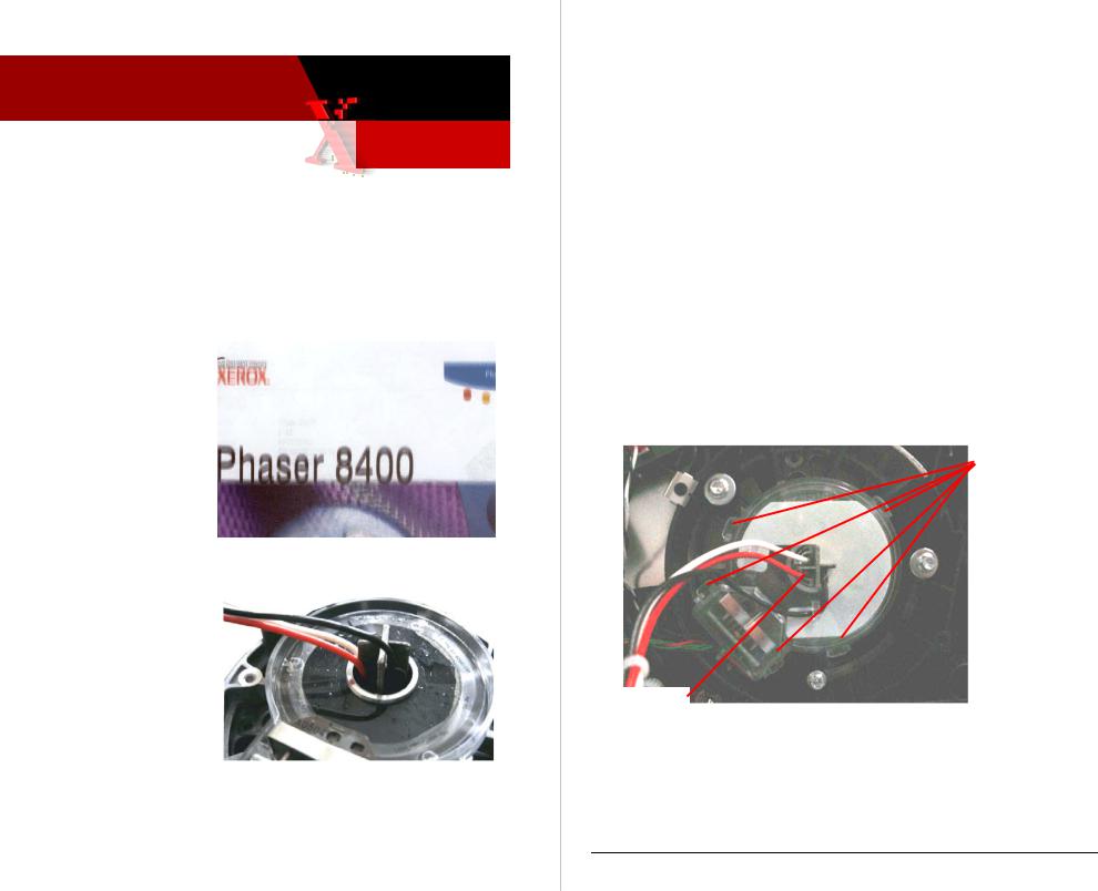
WHAT TO DO
Carefully disassemble the drum encoder’s cover to access the encoder disk and then clean the disk.
1.Turn off the printer.
2.Remove the right side cover.
3.Remove the drum fan.
4.Disconnect the drum assembly’s encoder wiring harness from the I/O board. Disconnect the drum heater wiring harness from the drum relay board.
NOTE: Observe for reassembly how the AC wiring harness routes thru the encoder disk cover and the heater frame.
5.Free the encoder wiring from the encoder cover.
6.Carefully pry off the transparent encoder cover by releasing its five snap-fit latches.
Snap-fit latches
Note wire routing
Figure 3
Page 2 of 3
Phaser 8400 |
Xerox Office Group Service Bulletin |
SB 705 |
|
|
|
7.Gently feed the AC wiring thru the encoder cover to move the cover out of the way.
8.With a cleaning swab, gently clean the oil off the encoder disk. If available, use Xerox cleaning fluid (p.n. 008R90176) to “cut” the oil.
9.Carefully reassembly the drum encoder. Be sure to correctly route the drum heater AC wiring thru the encoder disk cover and the heater frame.
10. Print some test prints.
PART INVENTORY STRATEGY
If cleaning repairs are not effective, replace the drum assembly, p.n. 105-1150-08
TE
Page 3 of 3

Xerox
Office Service Bulletin 01 Dec 2005
Group
SB 709
Phaser 8400/8500/8550
Revised Service Manual Available
INFORMATION
An updated version of the Phaser 8400/8500/8550 Color Printer Service Manual is available in PDF format. The files are available on the in the Phaser 8400 and the Phaser 8500/8550 pages of the Service Support website http://cpidserv.opbu.xerox.com/. The same files are also accessible thru the Service Partner website www.officeprinting.xerox.com/partners.
The single-file version of the service manual is a change-bar marked manual that indicates which topics are updated.
The individual chapter files do not contain the change bars.
The updated manual can be identified by the revision date Oct 24, 2005 on the title page.
WHAT TO DO
Download the manual files of your choice.
PART INVENTORY STRATEGY
Printed copies of the updated service manual will be available to order in January 2006 using part number 721P58550.
TE
Service Manual Rev 0 Page 1 of 1
Copyright © 2003 Xerox Corporation. All rights reserved. XEROX®, the stylized X®, and Phaser® trademarks of Xerox Corporation in the United States and/or other countries.

Xerox
Office Service Bulletin 14 Dec 2005
Group
SB 711
Phaser 8500/8550
Clarifications regarding using Jet Substitution and the Light Stripes Test Page
INFORMATION
Use the Light Stripes Test Page to determine the jet number of an unrecoverable weak or missing jet that you will want to fix using jet substitution. A weak or missing jet will always appear weak or missing on the Light Stripes Test print even when Jet Substitution is being used. Once jet substation is activated, a small, black dot is printed next to the jet number of a jet that will be substituted during normal printing.
Jet Substitution dot A sub’ed jet will still show as missing on Light Stripes print
Missing Jet |
Missing jet that will be substituted |
|
during regular printing |
WHAT TO DO
Note that Jet Substitution mode is enabled during normal printing but is not used when printing the Light Stripes Test page.
PART INVENTORY STRATEGY
None TE
Repair Notes
Rev 0
Page 1 of 1
Copyright © 2003 Xerox Corporation. All rights reserved. XEROX®, the stylized X®, and Phaser® trademarks of Xerox Corporation in the United States and/or other countries.

Xerox
Office Service Bulletin 14 Dec 2005
Group
SB 712
Phaser 8500/8550
Only Newest Firmware-Version Electronics Module (p.n. 137E14021) is Available; Uploading NarrowStyle Wiper Belt Snippet May Be Necessary
8,XXX.4X WIPER MOVEMENT ERROR CODES MAY OCCUR IF PRINTER FIRMWARE AND WIPER DRIVE BELTS DO NOT MATCH
Only replacement FRU electronic modules which contain the latest version firmware are now orderable. These electronic modules contain engine code version: vxWorks: 4.302; Engine: 18.P1.4.8.0; NW: 25.28.08.19.2005; PS: 4.8.0. As detailed in Service Bulletin 701, this firmware level implements metered printing capability as well as support for wide-style wiper drive belts.
WHAT TO DO
When you install a replacement electronics module in a printer you must verify what style of wiper drive belts are used in the printer.
Narrow wiper drive belt |
Wide wiper drive belt |
|
|
|
|
Repair Notes |
Rev 0 |
Page 1 of 2 |
Copyright © 2003 Xerox Corporation. All rights reserved. XEROX®, the stylized X®, and Phaser® trademarks of Xerox Corporation in the United States and/or other countries.
Phaser 8500/8550 |
Xerox Office Group Service Bulletin |
SB 712 |
|
|
|
If the printer uses narrow-style belt, you must upload the snippet 8500-8550useThinBelts.ps to set the firmware code to use narrow wiper belts.
Snippets to set the electronics module’s firmware to work with either narrowor wide-style belts are available at:
Service Partners http://www.office.xerox.com/partners/products/Phaser8500/Phaser8500Series.html
Internal Support http://cpidserv.opbu.xerox.com/products/Phaser8500/Phaser8500Series.html
By default, the electronics module is set to work with wide-style belts.
Be sure that the style of wiper drive belts matches the firmware version of the electronics module.
Refer to Service Bulletin 701. Be sure that the firmware version of the electronics module is correct for the style of wiper drive belts used.
FW Version 4.302 Default support for wide wiper belts Can be set to support narrow wiper belts
FW Version 4.278 Only support narrow wiper belts
Wiper movement error codes 08,xxx.4x may result if the firmware does not match the wiper belts.
PART INVENTORY STRATEGY
Order electronics modules only as needed.
Electronics Module |
137E14021 |
Wiper Assembly – wide style |
367053480 |
Wiper Drive Belts – wide style |
214501280 |
8400/8500/8550 |
|
TE
Page 2 of 2

Xerox
Office Service Bulletin 04 Jan 2006
Group
SB 714
Phaser 8400/8500/8550
Jam Open Front Cover (C3T) after Replacing or Reinstalling the Process Drive Assembly
PROCESS DRIVE ASSEMBLY ALIGNMENT PROBLEM
After replacing the process drive assembly, pivot plate or the drum maintenance camshaft (or any other procedure requiring the removal of the process drive assembly), the printer may experience jams from Tray 2. The jam occurs with paper in the preheater and C3T jam errors (strip flag timeout during transfix) recorded in the Jam History. In many cases, Tray 1 (MPT) prints with no jams.
These symptoms indicate that the transfix load module is incorrectly timed and is therefore not advancing the paper to the strip flag within the correct timeframe. Therefore the printer reports a front cover jam and records the C3T jam error.
WHAT TO DO
The majority of the time, the problem is that the drum maintenance camshaft is out of position by one or two teeth. Correct by:
1. Rotate the drum
maintenance camshaft |
|
Pin the process drive to |
||
clockwise to tilt the |
|
secure its missing tooth |
||
printhead forward to its |
|
gears |
||
home position. (This |
|
|
|
|
|
|
|
|
|
disengages the |
|
|
|
|
printhead and its tilt |
|
|
|
|
gear from the camshaft.) |
|
Drum maintenance |
||
2. Pin the process drive |
|
|||
|
camshaft |
|||
assembly to keep its two |
|
|
|
|
missing tooth gears in their disengaged positions. |
|
|
|
|
|
|
|
|
|
Repair Notes |
Rev 0 |
Page 1 of 2 |
||
Copyright © 2003 Xerox Corporation. All rights reserved. XEROX®, the stylized X®, and Phaser® trademarks of Xerox Corporation in the United States and/or other countries.
Phaser 8400/8500/8550 |
Xerox Office Group Service Bulletin |
SB 714 |
|
|
|
3. Remove the process drive assembly.
4. Press against the drum maintenance kit to force it (and the pivot plate) against the drum maintenance cams. This forces the drum maintenance shaft end gear to it home position. The camshaft’s homed
position is indicated by the hole in the drum maintenance camshaft gear aligning with the embossed arrow on the metal plate below the gear.
Note: When properly aligned, the hole in the camshaft gear points to the 6:00 or 5:30 position. If the hole does not point at the arrow, while the DMU is being pressed against the cams, a cam may be broken on the drum maintenance camshaft.
5.With the drum maintenance camshaft held in its home position, install the pinned process drive.
6. Once the process |
DMU horizontal |
drive assembly is |
|
secured in place, |
|
remove the lock |
|
pins. |
|
|
Camshaft gear |
|
alignment hole should |
|
be in this position |
PART INVENTORY STRATEGY
None
TE
Page 2 of 2

Xerox
Office Service Bulletin 20 Mar 2006
Group
SB 716 Rev 1
Phaser 8500/8550
Installing Pick Clutch Ground Clip Prevents 19,005.4 Error Codes, Printer Hangs During Printing, and some Jams Behind Front Cover
GROUND CLIP PREVENTS STATIC CHARGE BUILD-UP
Static build up at the pick roller during printing can lead to a static discharge thru the pick roller clutch into the electronics module. This results in either:
•A 19,005.41 error code displayed on the front panel.
•The printer hanging while printing with the electronics fan on full.
•Occasional Jams Behind the Front Cover messages. This jam is usually accompanied by error 19,005.41 in Fault History.
The static buildup occurs while printing in very low-humidity environments.
WHAT TO DO
Install a ground clip from the Y-axis motor bracket to the pick clutch.
1. Remove the lower-right |
|
|
|
|
|
|
|
|
|
|
|
|
|
Remove |
|
|
|
Y-axis motor mounting |
|
|
|
|
|
screw. It is the screw |
|
|
screw |
|
|
closest to the paper pick |
|
|
|
|
|
clutch. |
|
|
|
|
|
|
|
|
|
|
|
|
|
|
|
|
|
Repair Notes |
Rev 0 |
Page 1 of 2 |
Copyright © 2003 Xerox Corporation. All rights reserved. XEROX®, the stylized X®, and Phaser® trademarks of Xerox Corporation in the United States and/or other countries.
Phaser 8500/8550 |
Xerox Office Group Service Bulletin |
SB 716 |
|
|
|
2.Loosely install the ground clip and then the washer with the screw you just removed. The other end of the ground clip should contact the end of the paper pick clutch.
3.Position the ground clip so its end rests against the face of the pick clutch body. The corner of the ground clip end should contact the plastic frame of the media path drive module.
4.Tighten the screw to secure the ground clip in position.
Loosely install ground clip and washer
Position the clip so its edge contacts the clutch face and the plastic housing
PART INVENTORY STRATEGY
Update any Phaser 8500 or 8550 you service with a static ground clip as needed to solve 19,005.43 errors, some printer hangs during printing, and random jamming behind the front cover.
Pick Clutch Ground Clip Kit - Part Number 650-4427-00
TE
Page 2 of 2
Xerox
Office Service Bulletin 09-April-2006
Group
Phaser 8500/8550 |
SB 719 |
|
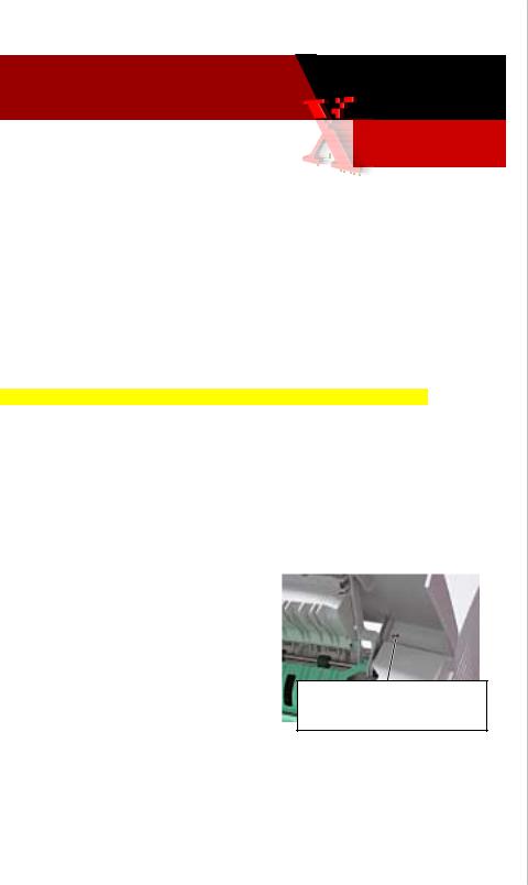
New Locking-Style ZIF Connector Being Used for Printhead Flex Cable
INFORMATION: THREE TYPES OF PRINTHEAD FLEX CABLE CONNECTORS ARE USED; ONE OF THEM IS A LOCKING ZIF CONNECTOR
Until recently, the Phaser 8500/8550 printers used two different non-locking style flex cable connectors. In order to meet new Reduction of Hazardous Substances (RoHS) standards, a third locking-style ZIF connector will be used. It replaces the use of the previous two connectors. Only the new locking-style ZIF connector meets electrical specifications and the RoHS standards.
Non-locking style connectors (white or black)
Locking style ZIF connector
|
Lift up on small tabs on |
|
|
each end of the connector |
|
|
to release the lock |
|
|
|
|
Part Issue |
Page 1 of 2 |
|
Copyright © 2006 Xerox Corporation. All rights reserved. XEROX®, the stylized X®, and Phaser® trademarks of Xerox Corporation in the United States and/or other countries.
Phaser |
Xerox Office Group Service Bulletin |
SB 719 |
|
|
|
WHAT TO DO
As you service a Phaser 8500 or 8550 printer, be aware that you may need to unlock and lock the flex cable when disconnecting and reconnecting the cable.
•Use care when locking and unlocking the connector.
•Failing to unlock a ZIF connector, before removing the cable, may damage the connector.
•Ensure the cable is fully inserted into the connector before locking the connector.
PART INVENTORY STRATEGY
None.
TME
Page 2 of 2

Xerox
Office Service Bulletin 11-April-2006
Group
Phaser 8500/8550 |
SB 720 |
Printer Produces Gradually Lighter Prints
INFORMATION: PRINTERS BELOW SERIAL-NUMBER WYP142312 AND WYN142344 BENEFIT FROM PRINTHEAD FIRMWARE UPDATE
Printhead engineering has developed new drift compensation algorithms that maintain the print quality/density of the Phaser 85xx printer’s printhead. All printers serial-numbered below WYN142344 (Phaser 8550) and WYP142312 (Phaser 8500) benefit from having their printhead’s firmware constants updated via a downloadable snippet file. Printers above the serial number break already have the new algorithm built in.
The snippet file and a readme file are contained in file 8500-8550_phfw- update.zip. The file is available at:
http://www.office.xerox.com/perl-bin/product.pl?page=sprt&product=8500_8550
Follow the readme instructions to upload the snippet to a printer.
As the printhead ages over the years, the prints it produces will gradually become lighter and lighter. There is no means to determine the printhead’s firmware constants settings. Only downloading the snippet to the printer will tell you if the printhead is up-to-date or not. Following the download, the printer prints a download status print.
WHAT TO DO
As you service a Phaser 8500 or 8550 printer, check its serial number. If it is below WYP142312 or WYN142344, download the printhead update snippet to the printer. For update tracking purposes, indicate in your call closure details or notes that you have updated a printer with the printhead snippet.
PART INVENTORY STRATEGY
None.
TME
Firmware Issue |
Page 1 of 1 |
Copyright © 2006 Xerox Corporation. All rights reserved. XEROX®, the stylized X®, and Phaser® trademarks of Xerox Corporation in the United States and/or other countries.

Xerox
Office Service Bulletin 8 May 2006
Group
Phaser 850/860/8200/8400/8500/ |
SB 723 |
8550/C2424 |
|
Back Channel Trace and Diagnostics using a USB-to-Serial Adapter
USING A USB-TO-SERIAL PORT ADAPTER TO OBTAIN A BACK CHANNEL TRACE OR TO RUN PHASER 850 DIAGNOSTICS
Many newer Laptops or PC’s do not have serial ports available. An alternate method of communicating with the printers is available by using a USB-to-Serial Port Adapter and its software to communicate in a serial manner.
WHAT TO DO
Obtain a USB-to-Serial Port Adapter and software for your Laptop or PC and Load the software as per the instructions provided.
An example of how to load and operate the Port Adapter is provided below.
Obtaining a VX Works Trace using a USB Adapter – This method was tested with a Phaser 850. You can also use the adaptor for running external Diagnostics after modifying the Diags.INI file.
NOTE The instructions contained in this service bulletin were developed using a Belkin USB/Serial Adapter, P/N F5U109 and the Windows XP O/S. Other USB-to-Serial adapters are available; however software installation procedures may vary by brand.
NOTE Xerox is not responsible for any changes made to your laptop or PC setup to make the adapter software function properly.
Testing Issue |
Page 1 of 3 |
Copyright © 2004 Xerox Corporation. All rights reserved. XEROX®, the stylized X®, and Phaser® trademarks of Xerox Corporation in the United States and/or other countries.
Solid Ink Printers |
Xerox Office Group Service Bulletin |
SB 723 |
|
|
|
1.Load the software from the CD and reboot the PC. Follow the instructions included with your adapter to install the necessary software.
2.Connect the USB/Serial adapter to an available USB port on your PC. Attach the port adapter to the 9 pin Serial cable (012-1535-00) and the diagnostic pig tail (012-1543-00), and plug it into the service port on the back of the printer
3.Configure the USB port for diagnostics. For Windows XP, go to [My Computer] - [Control Panel] - [System], select the [Hardware] tab, and then select [Device Manager]. Click on the “+” next to [Ports (COM & LPT)], then right click on the USB-to-Serial Port device and select [Properties]. Make a note of the port number (usually COM3 or COM4)
NOTE Check the USB/Serial adapter instructions for acceptable COM ports. Some adapters may require that the adapter use COM3 or COM4.
4.Click on the [Port Settings] tab. Set “Bits per second” to 19200, and set “Flow control” to Hardware, then click [OK].
5.Set up a Hyper Terminal port on the PC. Click [Start] - [Programs] - [Accessories] - [Communications] - [Hyper Terminal].
6.Name the new connection with the model number of the printer. Configure the new connection using the COM port configured in step 3, then click [OK]. Set “Bits per second” to 19200, and set “Flow control” to Hardware, then click [OK].
7.From the Hyper Terminal tool bar, click on [Transfer] and select [Capture Text]. Click on [Browse], and in the browse window, navigate to the desktop (or another file where you wish to save your diagnostic results). Enter a file name for your trace and click [Save].
8.For the Phaser 850, 860, and 8200 put rear panel DIP-switch 3 in the down position and turn on the printer. For the Phaser 8400/8500/8550 & C2424, no switch is needed. Follow the
Page 2 of 3

Solid Ink Printers |
Xerox Office Group Service Bulletin |
SB 723 |
|
|
|
instructions in the service manual for performing a backchannel trace.
9.The backchannel trace should be displayed in the Hyper Terminal window. When you have captured the necessary trace data, click [Transfer] – [Capture Text] – [Stop] to end data capture. This data will be saved as a text file to the location specified in step #7, and may now be faxed or e- mailed to EHS for help with troubleshooting problems on power up or other out of the ordinary problems where normal diagnostics may not run.
PHASER 850 DIAGNOSTICS
To run diagnostics using a USB-to-serial adapter you must edit the DIAGS.INI file to launch the correct baud rate and COM port. Edit the file with a program such as WordPad. You will also need to verify that your USB/Serial adapter software supports the COM port you want to use. Some manufacturers may require that the adapter is used on COM1 through COM4.
It is recommended that the NO-Floppy diagnostics from the Partners Web site be used for easy diagnostic operation. Always place switch 1 only in the down position on the Phaser 850 printer to run diagnostics.
The following are the settings that need to be changed in the DIAGS.INI file. Set the Port for the Com port you wish to use. The baud rate is normally set at 19200. Save the file and launch diagnostics.
PORT0 = COM1 |
baud: 0 |
= 9600 |
PORT1 = COM2 |
baud: 1 |
= 19200 |
PORT2 = COM3 |
baud: 2 |
= 38400 |
PORT3 = COM4 |
|
|
NOTE Beginning with the Phaser 860, all printers have built-in diagnostics capabilities and do not require the use of external diagnostics.
Page 3 of 3
Loading...