


TL-PA511
AV500 Mini Powerline Adapter
Rev: 1.0.0
1910010503
COPYRIGHT & TRADEMARKS
Specifications are subject to change without notice.  is a registered trademark of TP-LINK TECHNOLOGIES CO., LTD. Other brands and product names are trademarks or registered trademarks of their respective holders.
No part of the specifications may be reproduced in any form or by any means or used to make any derivative such as translation, transformation, or adaptation without permission from TP-LINK TECHNOLOGIES CO., LTD. Copyright © 2011 TP-LINK TECHNOLOGIES CO., LTD. All rights reserved.
http://www.tp-link.com

FCC STATEMENT
This equipment has been tested and found to comply with the limits for a Class B digital device, pursuant to part 15 of the FCC Rules. These limits are designed to provide reasonable protection against harmful interference in a residential installation. This equipment generates, uses and can radiate radio frequency energy and, if not installed and used in accordance with the instructions, may cause harmful interference to radio communications. However, there is no guarantee that interference will not occur in a particular installation. If this equipment does cause harmful interference to radio or television reception, which can be determined by turning the equipment off and on, the user is encouraged to try to correct the interference by one or more of the following measures:
•Reorient or relocate the receiving antenna.
•Increase the separation between the equipment and receiver.
•Connect the equipment into an outlet on a circuit different from that to which the receiver is connected.
•Consult the dealer or an experienced radio/ TV technician for help.
This device complies with part 15 of the FCC Rules. Operation is subject to the following two conditions:
1)This device may not cause harmful interference.
2)This device must accept any interference received, including interference that may cause undesired operation.
Any changes or modifications not expressly approved by the party responsible for compliance could void the user’s authority to operate the equipment.
CE Mark Warning
This is a class B product. In a domestic environment, this product may cause radio interference, in which case the user may be required to take adequate measures.
Important Safety Instructions
1.Do not open this product or attempt to service it; it may expose you to dangerous high voltage or other risks.
2.Do not operate this product near water.
3.Do not place or operate this product near a radiator or a heat register.
4.Do not expose this product to dampness, dust or corrosive liquids.
5.Do not connect this product or disconnect it from a wall socket during a lightning or a thunderstorm
6.Do not block the ventilation slots of this product, for insufficient airflow may harm it.
7.Do not put anything on this product.
8.Plug this product directly into a wall socket (100V~240V, 50~60Hz). Do not use an extension cord between this product and the AC power source.
9.When plugging this product into a wall socket, make sure that the electrical socket is not damaged, and that there is no gas leakage.
10.Place the connecting cables properly so that people won’t stumble or walk on it.
11.This product should be operated from the type of power indicated on the marking label. If you are not sure of the type of power available, consult the qualified technician.
12.Unplug this product from the mains and refer the product to qualified service personnel for the following conditions:
¾If liquid has been spilled on the product
¾If the product has been exposed to rain or water
13.Unplug this product from the wall socket before cleaning. Use a damp cloth for cleaning. Do not use liquid cleaners or aerosol cleaners.
14.The specification of the fuse is T2.5AL250V. To avoid damage, please do not change the fuse.
15.The Operating temperature is 0 ~40 (32 ~104 ).
16.The Storage temperature is -40 ~70 (-40 ~158 ).
|
CONTENTS |
|
Chapter 1 Introduction........................................................................................................................... |
1 |
|
1.1 |
LED Indicator.............................................................................................................................. |
2 |
1.2 |
Physical Interface ....................................................................................................................... |
3 |
Chapter 2 Connecting Mechanism........................................................................................................ |
4 |
|
2.1 |
Introduction ................................................................................................................................ |
4 |
2.2 |
Connection Instruction................................................................................................................ |
4 |
2.3 |
Hardware Connection – Computer ............................................................................................. |
4 |
2.4 |
Hardware Connection – Internet................................................................................................. |
5 |
Chapter 3 Installing Management Utility .............................................................................................. |
7 |
|
Chapter 4 Using the Management Utility............................................................................................ |
11 |
|
4.1 |
Main ......................................................................................................................................... |
11 |
|
4.1.1 Rename........................................................................................................................ |
13 |
|
4.1.2 Enter Password ............................................................................................................ |
14 |
|
4.1.3 Add Device ................................................................................................................... |
15 |
|
4.1.4 Reset ............................................................................................................................ |
16 |
4.2 |
Privacy ..................................................................................................................................... |
16 |
4.3 QoS .......................................................................................................................................... |
18 |
|
4.4 |
Diagnostics............................................................................................................................... |
18 |
4.5 About ........................................................................................................................................ |
20 |
|
Chapter 5 Advanced Feature: How to Use the Pair Buttons............................................................. |
21 |
|
5.1 |
Pair (Secure with 128 bits-AES) ............................................................................................... |
21 |
5.2 |
Set Up a Secured Powerline AV Network with the Pair Button ................................................. |
21 |
Appendix A: Troubleshooting Guide .................................................................................................. |
23 |
|
Appendix B: Specifications ................................................................................................................. |
24 |
|

TL-PA511 AV500 Mini Powerline Adapter
Chapter 1 Introduction
This device is an AV500 Mini Powerline Adapter which transforms your house’s existing electrical wiring into a ubiquitous networking infrastructure. Simply plug this AV500 Mini Powerline Adapter into an ordinary AC power outlet which will easily extend your Cable/xDSL broadband connection or existing Ethernet (LAN) network to any other electrical outlet in any room of a house without the need of any new cabling.
This Mini Powerline Adapter supports up to 500Mbps data rate over the existing household power circuit. With data rates of 500Mbps, full multimedia application can easily be supported throughout the whole house in addition to Internet access. This Mini Powerline Adapter uses the existing power lines installed in a home as a path to transmit digital data, voice, audio and video between devices.
To ensure data communication’s security and multimedia applications, this Mini Powerline Adapter support built-in 128-bit AES encryption. With minimum setup, you can install and use this Mini Powerline Adapter within minutes. The adapter adds two useful functions.
1 Existing connection with a new unassociated device added via the Pair Button.
2 Reset to default setting via the Management Utility.
A. System Requirement
a)At least two AC 100V ~ 240V (50~60Hz) power outlets with standard home power wiring
b)A computer with the following:
¾Operating System with TCP/IP installed
¾Pentium III compatible processor and above
¾Ethernet LAN card installed with TCP/IP protocol
¾64 MB RAM or more
¾50 MB of free disk space (Minimum)
¾CD-ROM Drive
B. Package Contents
The AV500 Mini Powerline Adapter package contains the following items:
¾One AV500 Mini Powerline Adapter (There are two AV500 Mini Powerline Adapters in Starter Kit)
¾One CAT-5 Ethernet Cable (There are two CAT-5 Ethernet Cables in Starter Kit)
¾One Quick Installation Guide
¾One Resource CD (Management Utility and User Guide)
If any of the above items is damaged or missing, please contact your dealer immediately.
1
TL-PA511 AV500 Mini Powerline Adapter
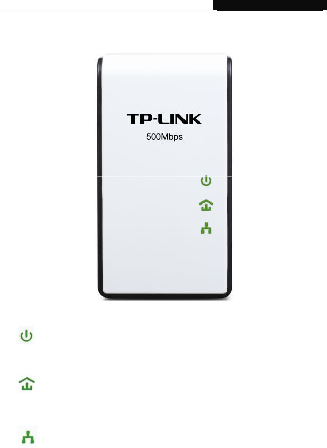
1.1 LED Indicator
The LED indicator displays information about the device’s status.
|
|
Item |
|
Status |
|
Indication |
|
|
|
|
On |
|
The adapter is on. |
|
|
Power LED |
|
Blinking |
The adapter is in power-saving mode. |
|
|
|
|
Off |
The adapter is off. |
||
|
|
|
|
|||
|
|
|
|
Green |
|
Data rate is more than or equal to 80Mbps. |
|
|
|
|
Orange |
|
Data rate is between 48Mbps and 80Mbps. |
|
|
Powerline LED |
|
Red |
|
Data rate is less than or equal to 48Mbps. |
|
|
|
|
Off |
|
The adapter isn’t connected to any powerline network or |
|
|
|
|
|
is in power-saving mode. |
|
|
|
|
|
|
|
|
|
|
|
|
On |
|
The Ethernet port is connected, but there is no data |
|
|
|
|
|
being transferred. |
|
|
|
|
|
|
|
|
|
|
Ethernet LED |
|
Blinking |
The Ethernet port is transferring data. |
|
|
|
|
|
Off |
The Ethernet port isn’t connected. |
|
) Note: |
|
|
|
|
||
5 minutes after the device connected to the adapter is turned off, the adapter will automatically switch to the power-saving Mode.
2
TL-PA511 AV500 Mini Powerline Adapter
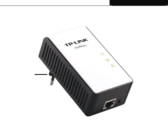
1.2 Physical Interface
There are four physical interfaces on this Mini Powerline Adapter.
Power Plug
|
|
|
|
|
Pair Button |
|
|
|
|
|
|
||
|
|
|
|
|
||
|
|
|
|
|
Ethernet Port |
|
|
|
|
|
|
||
|
|
|
|
|
|
|
Interface |
Description |
|||||
Ethernet Port |
A 10/100Mbps Ethernet port for connecting the adapter to the PC or |
|||||
the broadband device with a network cable. |
||||||
|
||||||
|
|
|
|
|
|
|
Power Plug* |
A Power Plug for connecting the adapter to a 100V ~ 240V |
|||||
(50~60Hz) AC power socket. |
||||||
|
|
|
|
|
|
|
|
Pair buttons are used to secure a powerline network. To secure |
|||||
|
your network, please follow the steps below. Firstly, plug in a new |
|||||
|
adapter, and press its pair button for one second; then plug in |
|||||
Pair Button |
another adapter and press its pair button for one second as well. |
|||||
|
The two buttons should be pressed within 2 minutes of each other. |
|||||
|
After that, wait about 60 seconds so that the two adapters can finish |
|||||
|
connecting. |
|||||
|
|
|
|
|
|
|
* The provided power plug may differ from the picture due to different regional power specifications. Here we take the EU version as an example.
) Note:
1.If you press the pair button for more than 10 seconds, the powerline adapter will leave the network which it has joined and its new network name assumes a random value. The Power LED turns off when it disconnects from the powerline network.
2.For detailed information about the pair button, please refer to Charpter 5 Advanced Feature: How to Use the Pair buttons.
3

TL-PA511 AV500 Mini Powerline Adapter
Chapter 2 Connecting Mechanism
2.1 Introduction
The Powerline Adapter supports up to 500Mbps data rate. With this high speed connection rate, this Powerline Adapter allows you to set up a high speed home network by using your home existing electrical wiring. Simply plug this Powerline Adapter into an ordinary power outlet to extend your Cable/xDSL broadband connection or existing LAN network to any other electrical outlet in any room of your house.
Note that this Powerline Adapter works in pairs. You need to plug one Powerline Adapter into a power outlet for each computer and connect the Powerline Adapter to the computer’s LAN card with an Ethernet cable; you will also need another Powerline Adapter connected to your Cable/xDSL broadband so as to extend your broadband connection or Internet surfing. With clean power line, the distance between two Powerline Adapters can reach 300 meters at lease, but the actual distance may vary due to the environment.
Section below describes the connection instructions and hardware connection mechanism.
2.2 Connection Instruction
To ensure the optimum performance of the Powerline Adapter and significantly improve the transmission capacity of the network, we recommend that you comply with the following connection rule:
yPlug the Powerline Adapter directly into a wall socket but not the multiple sockets.
2.3 Hardware Connection – Computer
For those computers you wish to be networked by Powerline Adapter, each of the computers must be properly connected with a Powerline Adapter through an Ethernet (RJ-45) cable.
Following are the steps to properly connect the Powerline Adapter to your computer:
1 Connect one end of the provided Ethernet (RJ-45) cable to the Powerline Adapter’s Ethernet port.
2 Connect the other end of the Ethernet (RJ-45) cable to you computer’s LAN port.
3 Plug the Powerline Adapter into a wall socket next to the computer.
4 Turn on your computer.
5 Check and confirm that the Power LED  and Ethernet LED


 on the Powerline Adapter are
ON.
4
 Loading...