


TD851W
Table of contents
 Loading...
TD851W
150Mbps Wireless N ADSL2+ Modem Router
Rev: 1.0.0
1910010472

COPYRIGHT & TRADEMARKS
Specifications are subject to change without notice. is a registered trademark
of TP-LINK TECHNOLOGIES CO., LTD. Other brands and product names are trademarks or
registered trademarks of their respective holders.
No part of the specifications may be reproduced in any form or by any means or used to make any
derivative such as translation, transformation, or adaptation without permission from TP-LINK
TECHNOLOGIES CO., LTD. Copyright © 2011 TP-LINK TECHNOLOGIES CO., LTD. All rights
reserved.
http://www.tp-link.com
FCC STATEMENT
This equipment has been tested and found to comply with the limits for a Class B digital device,
pursuant to part 15 of the FCC Rules. These limits are designed to provide reasonable protection
against harmful interference in a residential installation. This equipment generates, uses and can
radiate radio frequency energy and, if not installed and used in accordance with the instructions,
may cause harmful interference to radio communications. However, there is no guarantee that
interference will not occur in a particular installation. If this equipment does cause harmful
interference to radio or television reception, which can be determined by turning the equipment off
and on, the user is encouraged to try to correct the interference by one or more of the following
measures:
• Reorient or relocate the receiving antenna.
• Increase the separation between the equipment and receiver.
• Connect the equipment into an outlet on a circuit different from that to which the receiver
is connected.
• Consult the dealer or an experienced radio/ TV technician for help.
This device complies with part 15 of the FCC Rules. Operation is subject to the following two
conditions:
1) This device may not cause harmful interference.
2) This device must accept any interference received, including interference that may cause
undesired operation.
Any changes or modifications not expressly approved by the party responsible for compliance
could void the user’s authority to operate the equipment.
Note: The manufacturer is not responsible for any radio or tv interference caused by unauthorized
modifications to this equipment. Such modifications could void the user’s authority to operate the
equipment.

FCC RF Radiation Exposure Statement
This equipment complies with FCC RF radiation exposure limits set forth for an uncontrolled
environment. This device and its antenna must not be co-located or operating in conjunction with
any other antenna or transmitter.
“To comply with FCC RF exposure compliance requirements, this grant is applicable to only
Mobile Configurations. The antennas used for this transmitter must be installed to provide a
separation distance of at least 20 cm from all persons and must not be co-located or operating in
conjunction with any other antenna or transmitter.”
CE Mark Warning
This is a class B product. In a domestic environment, this product may cause radio interference, in
which case the user may be required to take adequate measures.
National restrictions
This device is intended for home and office use in all EU countries (and other countries following
the EU directive 1999/5/EC) without any limitation except for the countries mentioned below:
Country Restriction Reason/remark
Bulgaria None
Outdoor use limited to
France
Italy None
Luxembourg None
Norway Implemented
Russian
Federation
10 mW e.i.r.p. within the
band 2454-2483.5 MHz
None Only for indoor applications
General authorization required for outdoor use
and public service
Military Radiolocation use. Refarming of the 2.4
GHz band has been ongoing in recent years to
allow current relaxed regulation. Full
implementation planned 2012
If used outside of own premises, general
authorization is required
General authorization required for network and
service supply(not for spectrum)
This subsection does not apply for the
geographical area within a radius of 20 km from
the centre of Ny-Ålesund
Note: Please don’t use the product outdoors in France.

TP-LINK TECHNOLOGIES CO., LTD
DECLARATION OF CONFORMITY
For the following equipment:
Product Description: 150Mbps Wireless N ADSL2+ Modem Router
Model No.: TD851W
Trademark: TP-LINK
We declare under our own responsibility that the above products satisfy all the technical
regulations applicable to the product within the scope of Council Directives:
Directives 1999/5/EC
The above product is in conformity with the following standards or other normative documents
ETSI EN 300 328 V1.7.1: 2006
ETSI EN 301 489-1 V1.8.1:2008& ETSI EN 301 489-17 V2.1.1:2009
EN60950-1:2006
Recommendation 1999/519/EC
EN62311:2008
Directives 2004/108/EC
The above product is in conformity with the following standards or other normative documents
EN 55022:2006 +A1:2007
EN 55024:1998+A1:2001+A2:2003
EN 61000-3-2:2006
EN 61000-3-3:1995+A1:2001+A2:2005
Directives 2006/95/EC
The above product is in conformity with the following standards or other normative documents
EN60950-1:2006
Directive(ErP) 2009/125/EC
Audio/Video, information and communication technology equipment- Environmentally conscious
design
EN62075:2008
Person is responsible for marking this declaration:
Yang Hongliang
Product Manager of International Business
TP-LINK TECHNOLOGIES CO., LTD.
South Building, No.5 Keyuan Road, Central Zone, Science & Technology Park, Nanshan,
Shenzhen, P. R. China

CONTENTS
Package Contents .................................................................................................... 1
Chapter 1. Introduction ......................................................................................... 2
1.1 Product Overview ..................................................................................2
1.2 Main Features .......................................................................................2
1.3 Conventions ..........................................................................................3
Chapter 2. Hardware Installation .......................................................................... 4
2.1 The Front Panel.....................................................................................4
2.2 The Back Panel .....................................................................................5
2.3 Installation Environment ........................................................................6
2.4 Connecting the Modem Router..............................................................6
Chapter 3. Quick Installation Guide ..................................................................... 8
3.1 Configure PC.........................................................................................8
3.2 Login....................................................................................................11
Chapter 4. Software Configuration..................................................................... 15
4.1 Status ..................................................................................................15
4.1.1 Device Info............................................................................................... 15
4.1.2 Statistics ..................................................................................................17
4.1.3 Wizard...................................................................................................... 18
4.2 Setup...................................................................................................18
4.2.1 WAN ........................................................................................................18
4.2.2 LAN..........................................................................................................23
4.2.3 WLAN ......................................................................................................28
4.3 Advanced ............................................................................................42
4.3.1 Route ....................................................................................................... 43
4.3.2 NAT.......................................................................................................... 44
4.3.3 QoS.......................................................................................................... 50
4.3.4 CWMP .....................................................................................................55
4.3.5 Port mapping............................................................................................ 57
4.3.6 Others ...................................................................................................... 59
4.4 Service ................................................................................................59
4.4.1 IGMP Proxy..............................................................................................60
4.4.2 UPnP .......................................................................................................60

4.4.3 SNMP ......................................................................................................61
4.4.4 DNS ......................................................................................................... 62
4.4.5 DDNS....................................................................................................... 63
4.5 Firewall ................................................................................................64
4.5.1 MAC Filter................................................................................................ 64
4.5.2 IP/Port Filter............................................................................................. 66
4.5.3 URL Filter................................................................................................. 67
4.5.4 ACL..........................................................................................................68
4.6 Maintenance........................................................................................71
4.6.1 Update ..................................................................................................... 71
4.6.2 Password ................................................................................................. 74
4.6.3 System Restart ........................................................................................74
4.6.4 Time.........................................................................................................75
4.6.5 Log...........................................................................................................76
4.6.6 Diagnostic ................................................................................................77
Appendix A: Specifications ................................................................................... 82
Appendix B: Troubleshooting ............................................................................... 83
Appendix C: Technical Support ............................................................................ 92

TD851W 150Mbps Wireless N ADSL2+ Modem Router User Guide
Package Contents
The following contents should be found in your package:
¾ One TD851W 150Mbps Wireless N ADSL2+ Modem Router
¾ One Power Adapter for TD851W 150Mbps Wireless N ADSL2+ Modem Router
¾ Quick Installation Guide
¾ One RJ45 cable
¾ Two RJ11 cables
¾ One ADSL splitter
¾ One Resource CD, which includes this User Guide
Note:
)
Make sure that the package contains the above items. If any of the listed items are damaged or
missing, please contact your distributor.
1

TD851W 150Mbps Wireless N ADSL2+ Modem Router User Guide
Chapter 1. Introduction
Thank you for choosing the TD851W 150Mbps Wireless N ADSL2+ Modem Router.
1.1 Product Overview
The device is designed to provide a simple and cost-effective ADSL Internet connection for a
private Ethernet or IEEE 802.11n/ IEEE 802.11g/ IEEE 802.11b wireless network.
The TD851W connects to an Ethernet LAN or computers via standard Ethernet ports. The ADSL
connection is made using ordinary telephone line with standard connectors. Multiple workstations
can be networked and connected to the Internet using a single Wide Area Network (WAN)
interface and single global IP address. The advanced security enhancements, MAC Filter, IP/Port
Filter, URL Filter and ACL can help to protect your network from potentially devastating intrusions
by malicious agents from the outside of your network.
Wizard of the Web-based Utility is supplied and friendly help messages are provided for the
configuration. Network and Router management is done through the Web-based Utility which can
be accessed through local Ethernet using any web browser.
ADSL
The TD851W supports full-rate ADSL2+ connectivity conforming to the ITU and ANSI
specifications. In addition to the basic DMT physical layer functions, the ADSL2+ PHY supports
dual latency ADSL2+ framing (fast and interleaved) and the I.432 ATM Physical Layer.
Wireless
In the most attentive wireless security, the Router provides multiple protection measures. It can be
set to turn off the wireless network name (SSID) broadcast so that only stations that have the
SSID can be connected. The Router provides wireless LAN 64/128-bit WEP encryption security,
WPA-PSK/WPA2-PSK authentication, as well as TKIP/AES encryption security.
1.2 Main Features
¾ Wireless AP, Router, 4 Port Switch and Firewall
¾ Support ITU-T G.992.1 (G.dmt), ANSI T1.413, G.992.2 (G.Lite), ADSL2 and ADSL2+
¾ Support 802.11n, compatible with 802.11b and 802.11g
¾ Up to 54 Mbps wireless operation rate
¾ 64/128 bits WEP for security
¾ WPA and WPA2 support
¾ 1 10/100MBase-T Ethernet interface (LAN)
2

¾ RFC-1483/2684 LLC/VC-Mux bridge/route mode
¾ RFC-1577 Classical IP over ATM
¾ RFC-2516 PPPoE
¾ RFC-2364 PPPoA
¾ ITU-T 1.610 F4/F5 OAM send and receive loop-back
¾ 802.1d Spanning-Tree Protocol
¾ DHCP Client/Server/Relay
¾ NAT
¾ RIP v1/v2
¾ DNS Relay Agent
¾ Support DMZ, virtual server, ALG
¾ IGMP Proxy/Snooping
¾ Protection against Denial of Service attack
¾ IP Packet filtering
TD851W 150Mbps Wireless N ADSL2+ Modem Router User Guide
¾ MAC filtering
¾ URL filtering
¾ IP QoS
¾ Dynamic DNS
¾ UPnP support
¾ System log support, can record the state of the router
¾ Remote management
¾ SNMP v1/v2/Trap
¾ Firmware upgrade through FTP, TFTP and HTTP
¾ Configuration backup/restore
¾ Diagnostic tools
1.3 Conventions
The Router or device mentioned in this User Guide stands for TD851W without any explanations.
Parameters provided in the pictures are just references for setting up the product, which may differ
from the actual situation.
3
TD851W 150Mbps Wireless N ADSL2+ Modem Router User Guide
Chapter 2. Hardware Installation
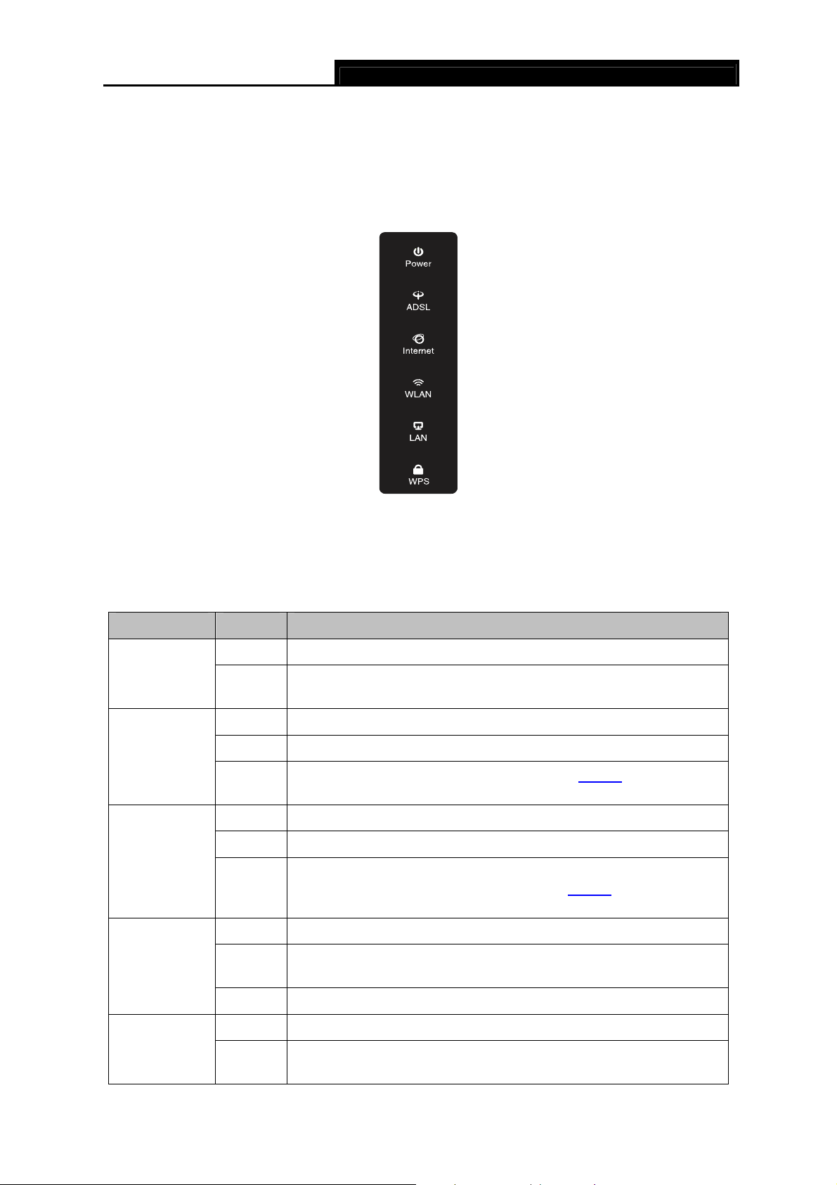
2.1 The Front Panel
Figure 2-1
The LEDs locate on the front panel. They indicate the device’s working status. For details, please
refer to LED Explanation.
LED Explanation
Name Status Indication
On The modem router is powered on.
Power
ADSL
Internet
Off
On ADSL line is synchronized and ready to use.
Flash The ADSL negotiation is in progress.
Off
On The network is available with a successful Internet connection.
Flash There is data being transmitted or received via the Internet.
Off
The modem router is off. Please ensure that the power adapter is
connected correctly.
ADSL synchronization fails. Please refer to Note 1
troubleshooting.
There is no successful Internet connection or the modem router is
operating in Bridge mode. Please refer to Note 2
troubleshooting.
for
for
WLAN
On Wireless is enabled but no data is being transmitted.
Flash
Off Wireless function is disabled.
On There is a device connected to this LAN port. LAN
Flash
The modem router is sending or receiving data over the wireless
network.
The modem router is sending or receiving data over this LAN
port.
4
Off There is no device connected to this LAN port.
TD851W 150Mbps Wireless N ADSL2+ Modem Router User Guide
On
WPS
Note:
)
1. If the ADSL LED is off, please check your Internet connection first. Refer to 2.4 Connecting
the Modem Router for more information about how to make Internet connection correctly. If
you have already made a right connection, please contact your ISP to make sure if your
Internet service is available now.
2. If the Internet LED is off, please check your ADSL LED first. If your ADSL LED is also off,
please refer to Note 1. If your ADSL LED is GREEN ON, please check your Internet
configuration. You may need to check this part of information with your ISP and make sure
everything have been input correctly. Refer to 4.1.1 Device Info
information.
Flash
Off
A wireless device has been successfully added to the network by
WPS function.
WPS handshaking is in process and will continue for about 2
minutes. Please press the WPS button on other wireless devices
that you want to add to the network while the LED is flashing.
The WPS function is disabled or the wireless device fails to be
added to the network in 2 minutes after WPS function is enabled.
Please refer to 4.2.3.6 WPS
for more information.
and 4.2.1 WAN for more
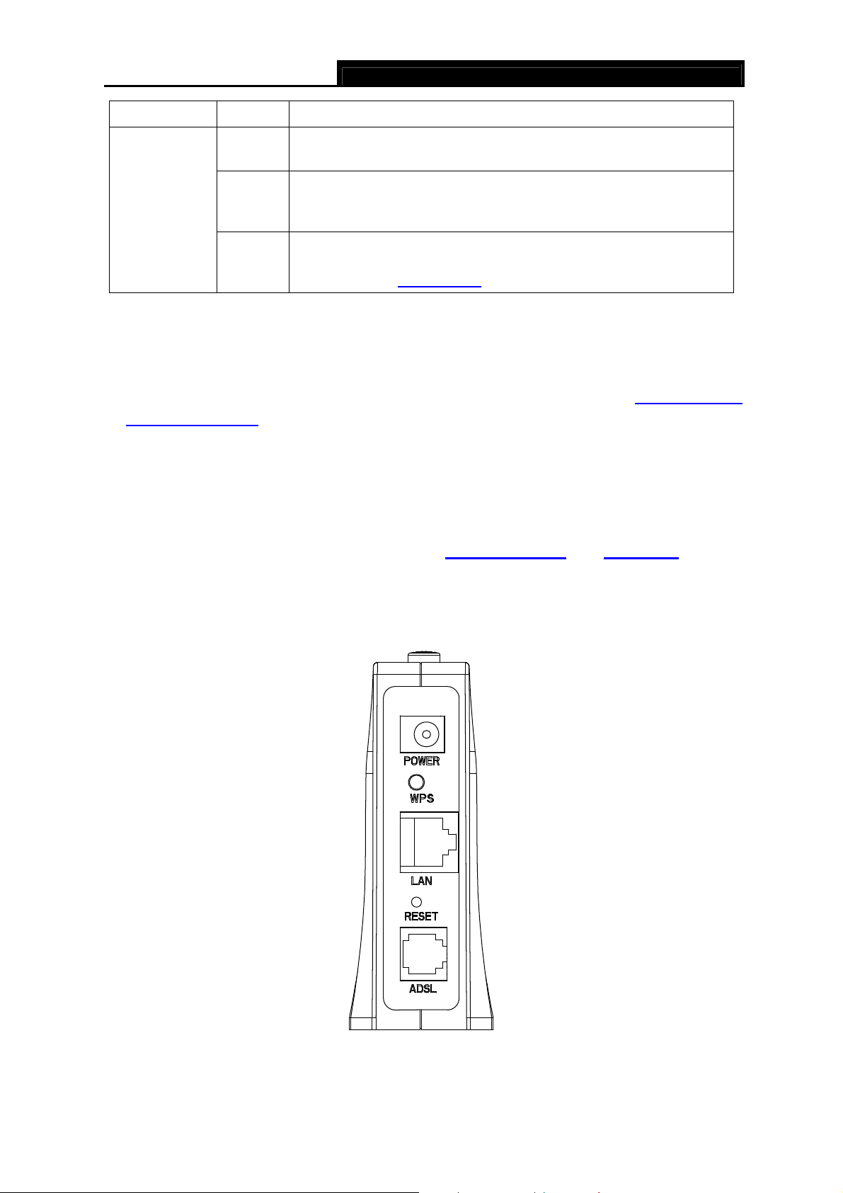
2.2 The Back Panel
Figure 2-2
¾ ON/OFF: The power switch for the Router.
5

¾ POWER: The Power plug is where you will connect the power adapter.
TD851W 150Mbps Wireless N ADSL2+ Modem Router User Guide
¾ WPS: The switch for the WPS function. For details, please refer to 4.3.3.1 WPS Settings
¾ LAN: Through the port, you can connect the Router to your PC or the other Ethernet network
devices.
¾ RESET: There are two ways to reset the Router's factory defaults.
Method one: With the Router powered on, use a pin to press and hold the Reset button for at
least 5 seconds. And the Router will reboot to its factory default settings.
Method two: Restore the default setting from “Maintenance-SysRestart” of the Router's
Web-based Utility.
¾ ADSL: Through the port, you can connect the Router with the telephone. Or you can connect
them by an external separate splitter. For details, please refer to 2.4 Connecting the Modem
Router.
.
2.3 Installation Environment
¾ The Product should not be located where it will be exposed to moisture or excessive heat.
¾ Place the Router in a location where it can be connected to the various devices as well as to a
power source.
¾ Make sure the cables and power cord are safely placed out of the way so they do not create a
tripping hazard.
¾ The Router can be placed on a shelf or desktop.
¾ Keep away from the strong electromagnetic radiation and the device of electromagnetic
sensitive.
2.4 Connecting the Modem Router
Back to LED Explanation
Before installing the device, please make sure your broadband service provided by your ISP is
available. If there is any problem, please contact your ISP. Before cable connection, cut off the
power supply and keep your hands dry. You can follow the steps below to install it.
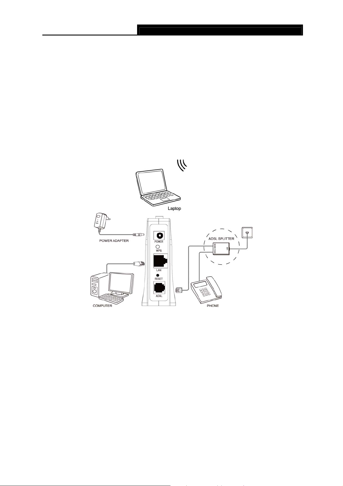
Step 1: Connect the ADSL Line.
Method one: Plug one end of the twisted-pair ADSL cable into the ADSL port on the rear
panel of TD851W, and insert the other end into the wall socket.
Method two:You can use a separate splitter. External splitter can divide the data and
voice, and then you can access the Internet and make calls at the same time. The
external splitter has three ports:
• LINE: Connect to the wall jack
• PHONE: Connect to the phone sets
6
• MODEM: Connect to the ADSL port of TD851W
Plug one end of the twisted-pair ADSL cable into the ADSL LINE port on the rear panel of
TD851W. Connect the other end to the MODEM port of the external splitter.
Step 2: Connect the Ethernet cable. Attach one end of a network cable to your computer’s
Ethernet port or a regular hub/switch port, and the other end to the LAN port on the
TD851W.
Step 3: Power on the computers and LAN devices.
Step 4: Attach the power adapter. Connect the power adapter to the power connector on the rear
of the device and plug in the adapter to a wall outlet or power extension, and then power
on the device. The electrical outlet shall be installed near the device and shall be easily
accessible.
TD851W 150Mbps Wireless N ADSL2+ Modem Router User Guide
Figure 2-3
7
TD851W 150Mbps Wireless N ADSL2+ Modem Router User Guide
Chapter 3. Quick Installation Guide
3.1 Configure PC
After you directly connect your PC to the TD851W or connect your adapter to a Hub/Switch which
has connected to the Router, you need to configure your PC’s IP address. Follow the steps below
to configure it.
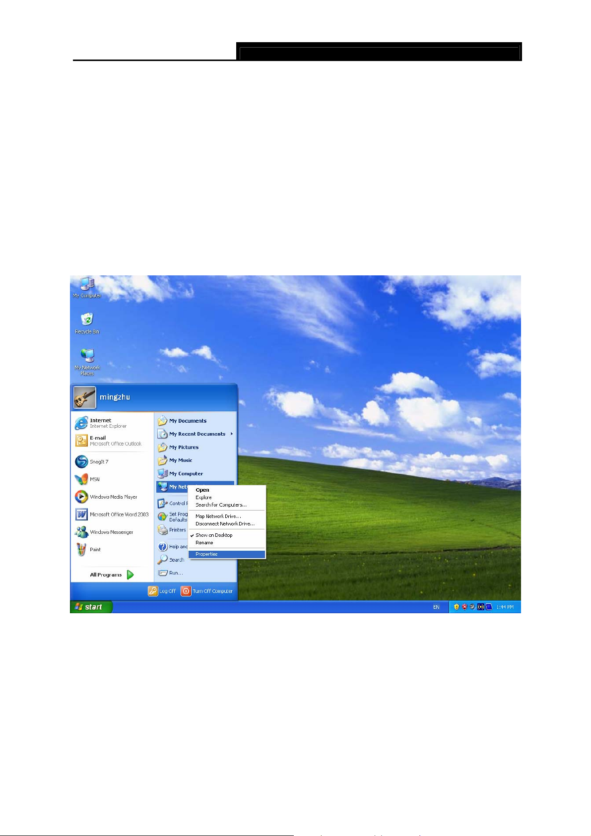
Step 1: Click the Start menu on your desktop, right click My Network Places, and then select
Properties (shown in Figure 3-1).
Figure 3-1
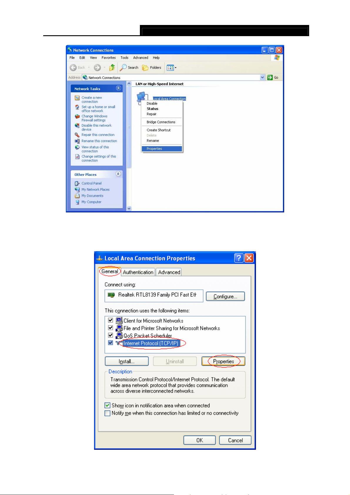
Step 2: Right click Local Area Connection (LAN), and then select Properties.
8
TD851W 150Mbps Wireless N ADSL2+ Modem Router User Guide
Figure 3-2
Step 3: Select General tab, highlight Internet Protocol (TCP/IP), and then click the Properties
button.
9
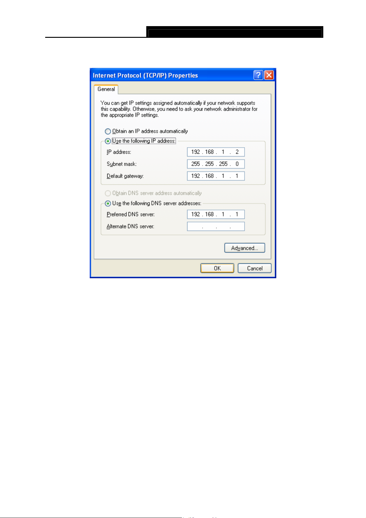
Step 4: Configure the IP address as Figure 3-4 shows. After that, click OK.
TD851W 150Mbps Wireless N ADSL2+ Modem Router User Guide
Figure 3-3
Figure 3-4
Note:
)
You can configure the PC to get an IP address automatically, select “Obtain an IP address
automatically” and “Obtain DNS server address automatically” in the screen above.
Now, you can run the Ping command in the command prompt to verify the network connection.
Please click the Start menu on your desktop, select run tab, type cmd or command in the field
and press Enter. Type ping 192.168.1.1 on the next screen, and then press Enter.
If the result displayed is similar to the screen below, the connection between your PC and the
Router has been established.
10
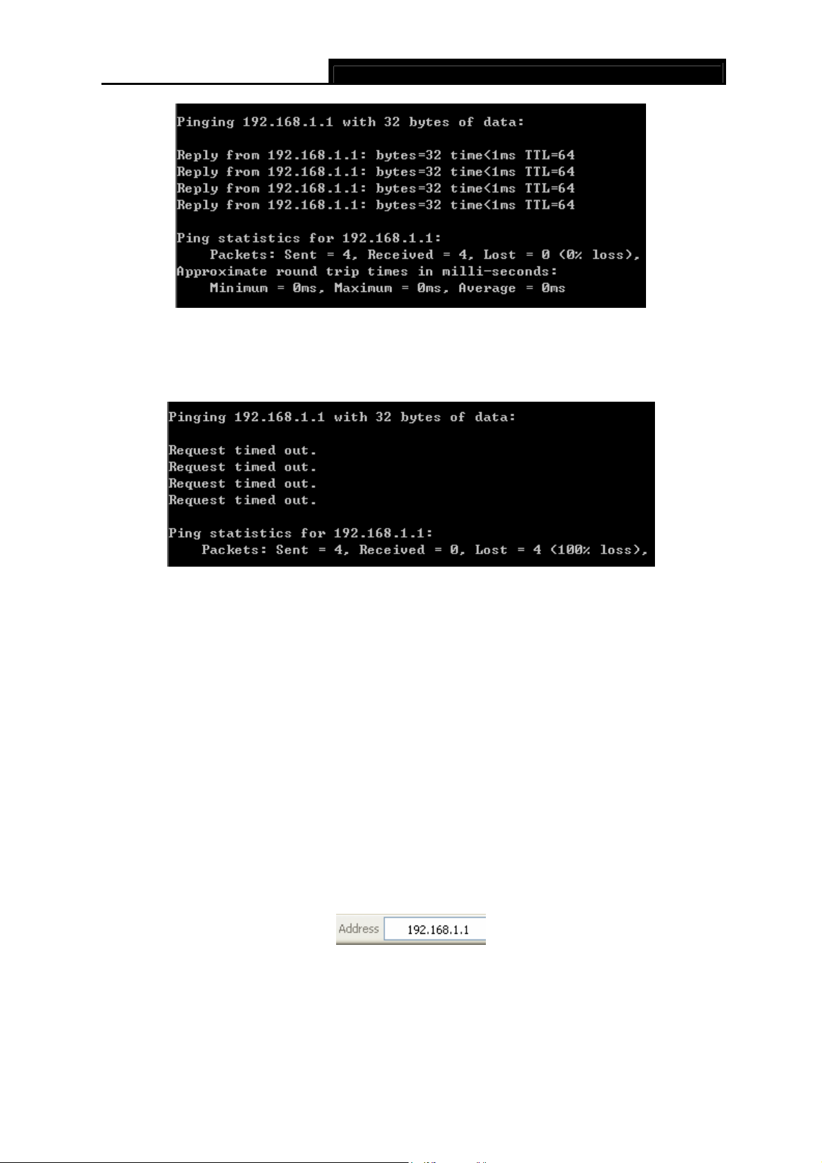
If the result displayed is similar to the screen shown below, it means that your PC has not
connected to the Router.
TD851W 150Mbps Wireless N ADSL2+ Modem Router User Guide
Figure 3-5
Figure 3-6
You can check it follow the steps below:
1) Is the connection between your PC and the Router correct?
The LEDs of LAN port which you link to the device and the LEDs on your PC's adapter should
be lit.
2) Is the TCP/IP configuration for your PC correct?
If the Router's IP address is 192.168.1.1, your PC's IP address must be within the range of
192.168.1.2 ~ 192.168.1.254.
3.2 Login
Once your host PC is properly configured, please proceed as follows to use the Web-based Utility:
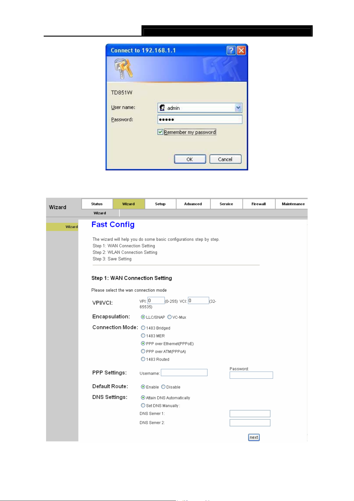
Start your web browser and type the private IP address of the Router in the URL field: 192.168.1.1.
After that, you will see the screen shown below, enter the default User name (admin) and the
default Password (admin), and then click OK to access to the Web-based Utility of the Router.
11
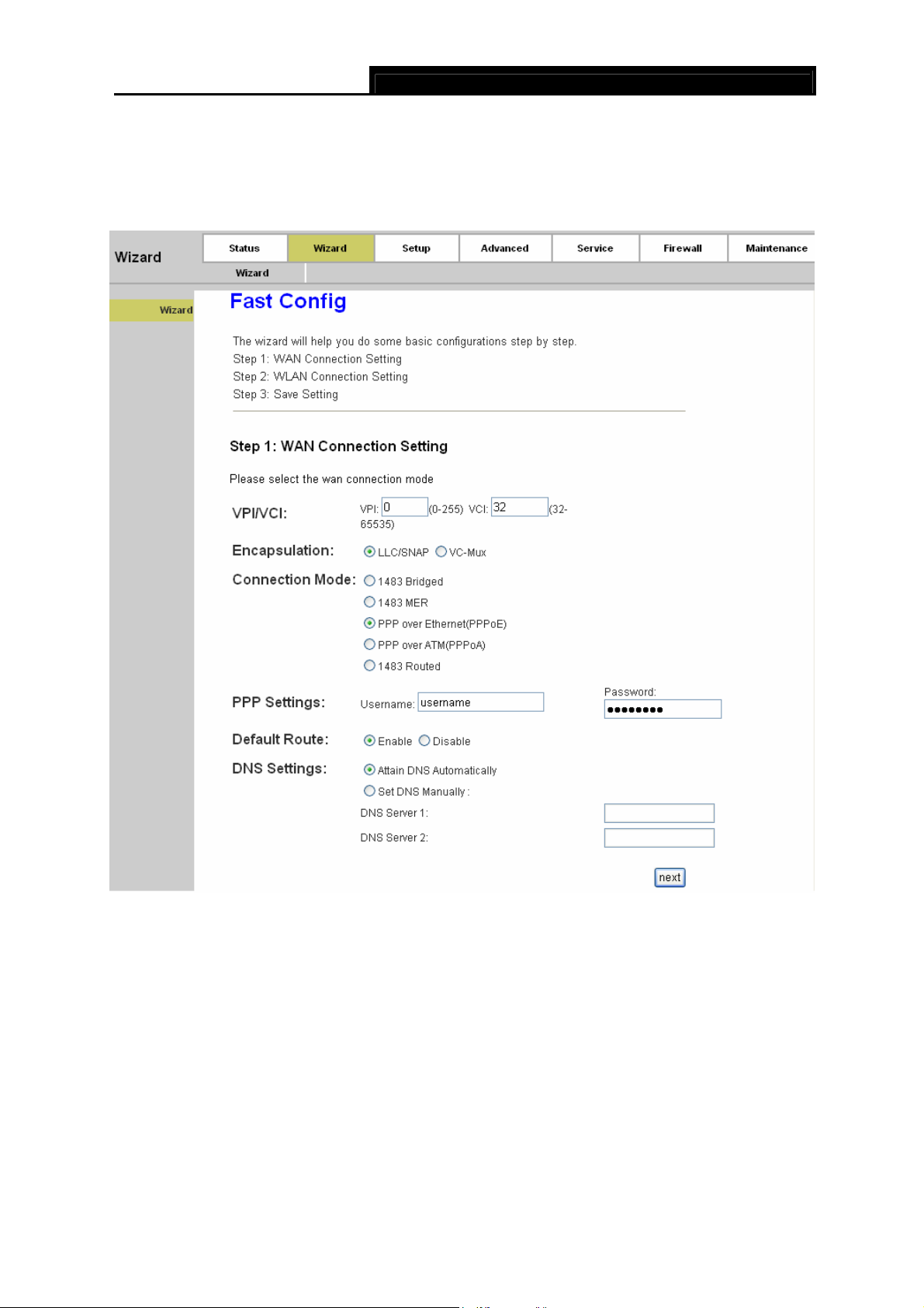
Step 1: Select the Wizard tab and you will see the next screen.
TD851W 150Mbps Wireless N ADSL2+ Modem Router User Guide
Figure 3-7
Figure 3-8
12
TD851W 150Mbps Wireless N ADSL2+ Modem Router User Guide
Step 2: Configure the Router with the information provided by your ISP, including VPI/VCI,
Connection Mode and the following parameters. Take PPPoE for example, you need to
enter Username, Password and DNS parameters. All these information are provided by
your ISP. After that, click the next button to continue.
Figure 3-9
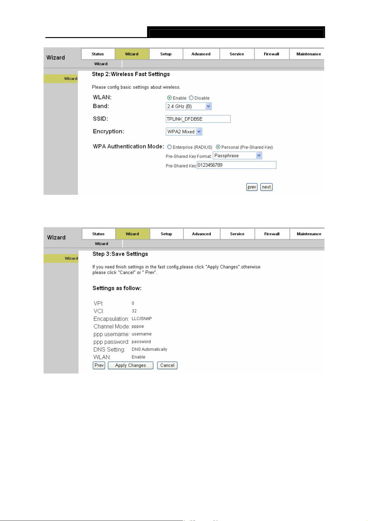
Step 3: Choose to enable your wireless network or not. If it’s enabled, you need to create
for your wireless network. It’s recommended that the name be unique and easy to
remember. You can also keep default without the device being affected. Select an
Encryption and Authentication Mode for the security of your wireless network, and
then enter the key in the corresponding field. After that, click the next button to continue.
13
a name
TD851W 150Mbps Wireless N ADSL2+ Modem Router User Guide
Figure 3-10
Step 4: Click the Apply Changes button to finish the wizard.
Figure 3-11
14
TD851W 150Mbps Wireless N ADSL2+ Modem Router User Guide
Chapter 4. Software Configuration
This User Guide recommends using the “Quick Installation Guide” for first-time installation. For
advanced users, if you want to know more about this device and make use of its functions
adequately, maybe you will get help from this chapter to configure the advanced settings through
the Web-based Utility.
After your successful login, you can configure and manage the device. There are main menus on
the top of the Web-based Utility; submenus will be available after you click one of the main menus.
On the center of the Web-based Utility, there are the detailed configurations or status information.
To apply any settings you have altered on the page, please click the SAVE button.
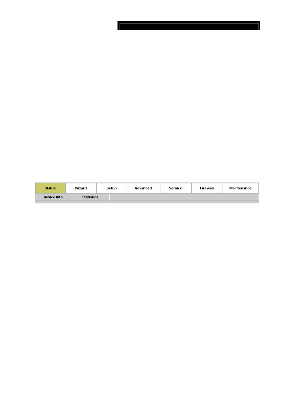
4.1 Status
Choose “Status”, you can see the next submenus: Device Info and Statistics. Click any of them,
and you will be able to configure the corresponding function.
Click any of them, and you will be able to view the corresponding information.
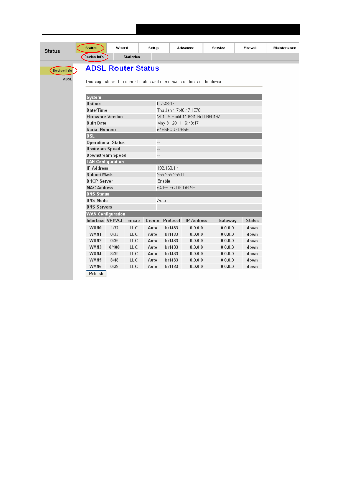
4.1.1 Device Info
4.1.1.1 Device Info
Back to LED Explanation
Choose “Status→Device Info→Device Info” menu, and you will be able to view the device
information, including System, DSL, LAN, DNS, and WAN. The information will vary depending on
the settings of the Router.
15
TD851W 150Mbps Wireless N ADSL2+ Modem Router User Guide
Figure 4-1
Click the Refresh button to refresh immediately.
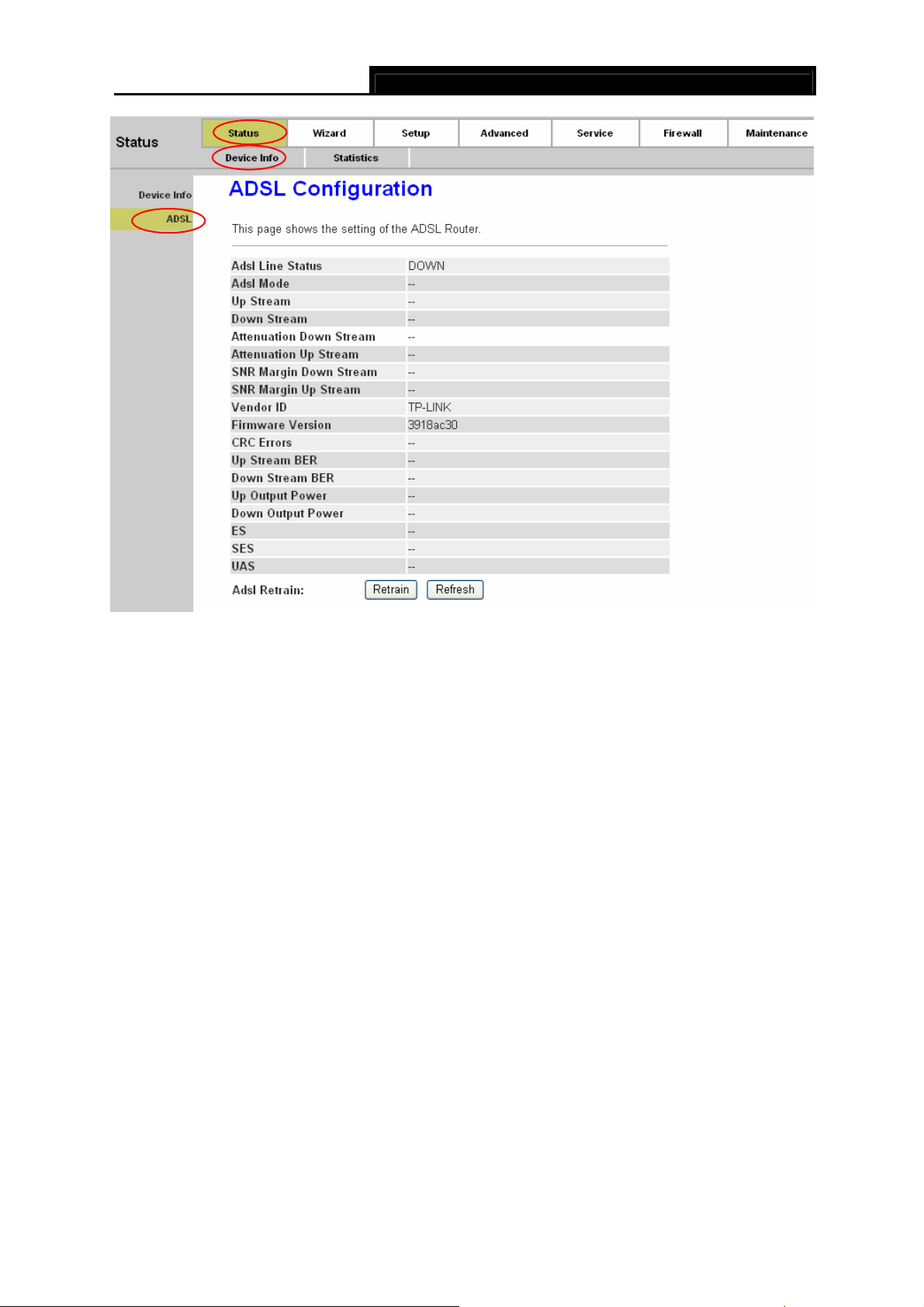
4.1.1.2 ADSL
Choose “Status→Device Info→ADSL” menu, and you will be able to view the ADSL
configuration.
16
TD851W 150Mbps Wireless N ADSL2+ Modem Router User Guide
Figure 4-2
Click the Retrain button to retrain the information again.
Click the Refresh button to refresh immediately.
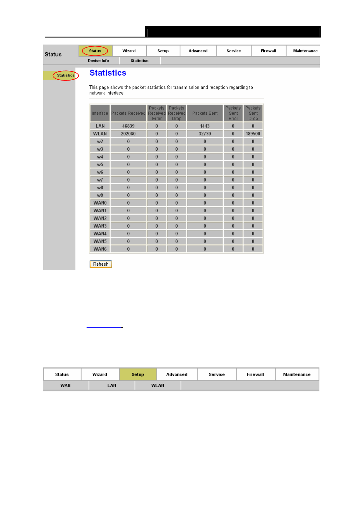
4.1.2 Statistics
Choose “Status→Statistics” menu, and you will be able to view the network traffic.
17
TD851W 150Mbps Wireless N ADSL2+ Modem Router User Guide
Figure 4-3
Click the Refresh button to refresh immediately.
4.1.3 Wizard
Please refer to " 3.2: Login".
4.2 Setup
Choose “Setup”, you can see the next submenus: WAN, LAN and WLAN.
Click any of them, and you will be able to configure the corresponding function.
4.2.1 WAN
4.2.1.1 WAN
18
Back to LED Explanation
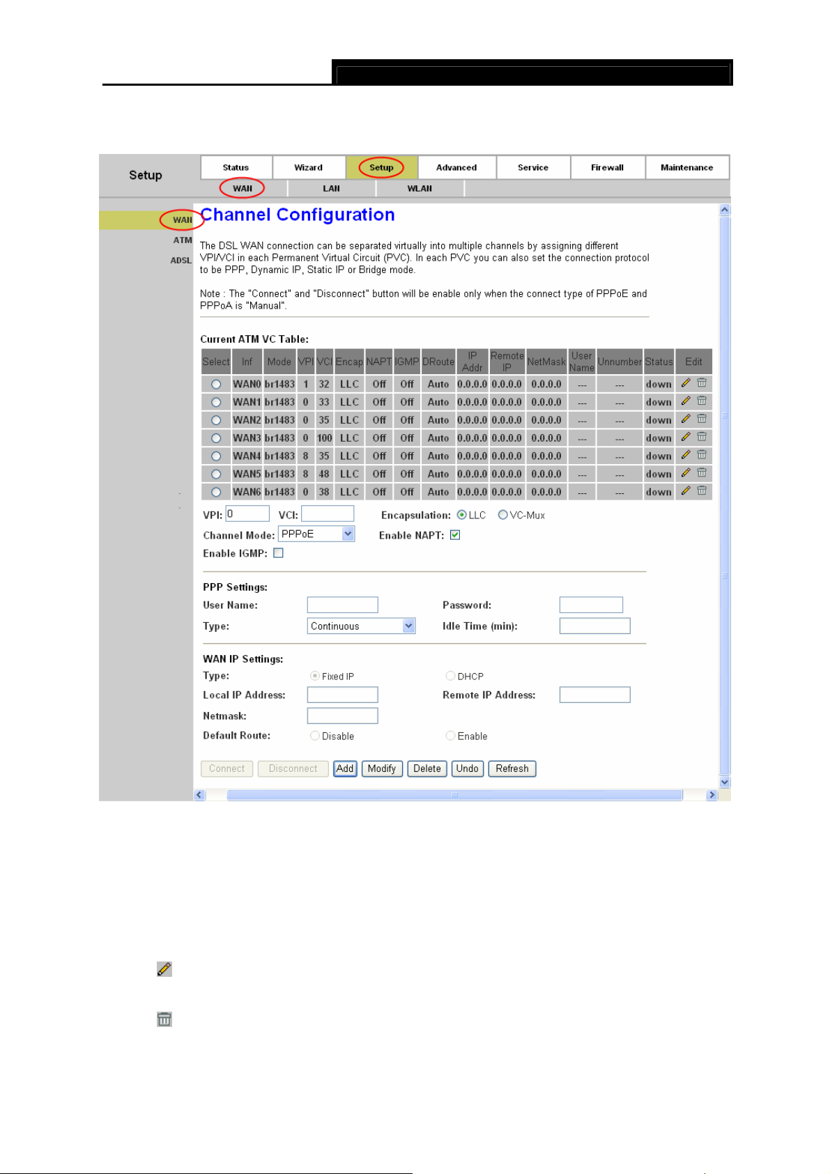
Choose “Setup→WAN→WAN” menu, you can configure the parameters for WAN in the next
screen (shown in Figure 4-4).
TD851W 150Mbps Wireless N ADSL2+ Modem Router User Guide
Figure 4-4
¾ Current ATM VC Table: ATM settings are used to connect to your ISP. Your ISP provides
VPI (Virtual Path Identifier), VCI (Virtual Channel Identifier) settings to you. In this Device,
there is one VC configured by default. You can totally setup 8 VCs on different encapsulations,
if you apply 8 different virtual circuits from your ISP. You need to activate the VC to take
effect.
•
•
: Click this icon to enter the VC modification page. Besides, some advanced settings
can be configured there.
: Click this icon to delete the corresponding VC.
19

• VPI: Identifies the virtual path between endpoints in an ATM network. The valid range is
from 0 to 255. Please input the value provided by your ISP.
• VCI: Identifies the virtual channel endpoints in an ATM network. The valid range is from
32 to 65535 (1 to 31 is reserved for well-known protocols). Please input the value
provided by your ISP.
• Encapsulation: Specifies the type of Multiplexing, either LLC or VC-Mux. Please note
that VC-Mux is not available for IPoA channel mode.
• Channel Mode: There are six channel modes, 1483 Bridged, 1483 MER, PPPoE,
PPPoA, 1483 Routed and IPoA. Please choose the mode that you want to use.
• Enable NAPT: Choose to enable the NAPT function or not.
• Enable IGMP: Choose to enable the IGMP function or not.
¾ PPP Settings: These parameters are only available for PPPoE and PPPoA channel mode.
• User Name: Enter your user name for your PPPoE/PPPoA connection.
TD851W 150Mbps Wireless N ADSL2+ Modem Router User Guide
• Password: Enter your password for your PPPoE/PPPoA connection.
• Type: Select Continuous, Connect on Demand or Manually for the network
connection. Continuous means the Internet connection will always keep on. Connect
on demand is dependent on the traffic. If it’s idle (there is no traffic) for a pre-specified
period of time), the connection will tear down automatically. And once there is traffic send
or receive, the connection will be automatically on. Manually means you have to
manually connect or disconnect your Internet by clicking the Connect or Disconnect
button at the bottom of this page.
• Idle Time (min): Specifies the idle time for Connect on Demand type.
¾ WAN IP Settings: These parameters are only available for 1483 MER and 1483 Routed
channel mode. Please note that for1483 Routed mode, DHCP is not available.
• Type: Selects to use Fixed IP or DHCP. If Fixed IP is selected, then you have to fill the
following parameters, including Local IP Address, Remote IP Address, and Netmask.
Otherwise, these parameters will not be available.
• Local IP Address: The IP address of the router on the PVC channel.
• Remote IP Address: The gateway’s IP address of the router on the PVC channel.
• Netmask: The subnet mask of the router on the PVC channel.
¾ Connect/Disconnect: When there is a VC using PPPoE/PPPoA channel and Manually type,
you need to click this button to connect/disconnect the network.
20
¾ Add: Click this button to add a VC. First fill the parameters above and then click this button,
thus your new VC will be added to the Current ATM VC Table.
¾ Modify: Click this button to modify your existed VC. First choose the desired VC and modify
the parameters, and then click this button, thus your existed VC will be modified.
¾ Delete: Click this button to delete your existed VC. First choose the desired VC, and then
click this button, thus your existed VC will be deleted.
¾ Undo: Click this button to abandon your operation.
¾ Refresh: Click this button to refresh the ATM VC table.
Note:
)
After configuration, you need to click the Save button appeared on the left panel so that your
configuration can still take effect after the Router reboots.
TD851W 150Mbps Wireless N ADSL2+ Modem Router User Guide
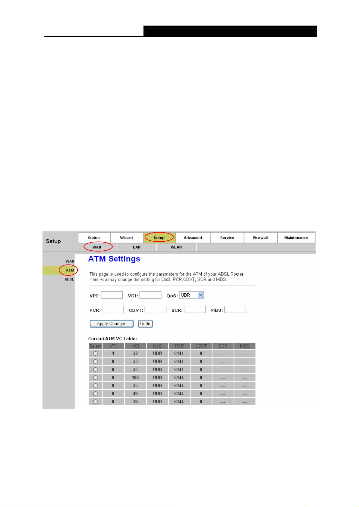
4.2.1.2 ATM
Choose “Setup→WAN→ATM” menu, you can configure the parameters for the ATM of your
ADSL Router in the next screen (shown in Figure 4-4). Here you may change the setting for QoS,
PCR, CDVT, SCR and MBS.
Figure 4-5
¾ VPI/VCI: Choose a desired ATM VC, and the VPI/VCI value will be displayed. The values can
not be changed.
21
¾ QoS: Select the Quality of Service types for the Virtual Circuit, including UBR (Unspecified Bit
Rate), CBR (Constant Bit Rate), and nrt-VBR (Variable Bit Rate) and rt-VBR. Please note that
the selection of QoS type will lead to the availability of the following parameters, including
PCR (Peak Cell Rate), CDVT (Cell Delay Variation Tolerance), SCR (Sustained Cell Rate)
and MBS (Maximum Burst Size). Please configure them according to your needs.
Click Apply Changes to save your configuration.
Note:
)
After configuration, you need to click the Save button appeared on the left panel so that your
configuration can still take effect after the Router reboots.
TD851W 150Mbps Wireless N ADSL2+ Modem Router User Guide
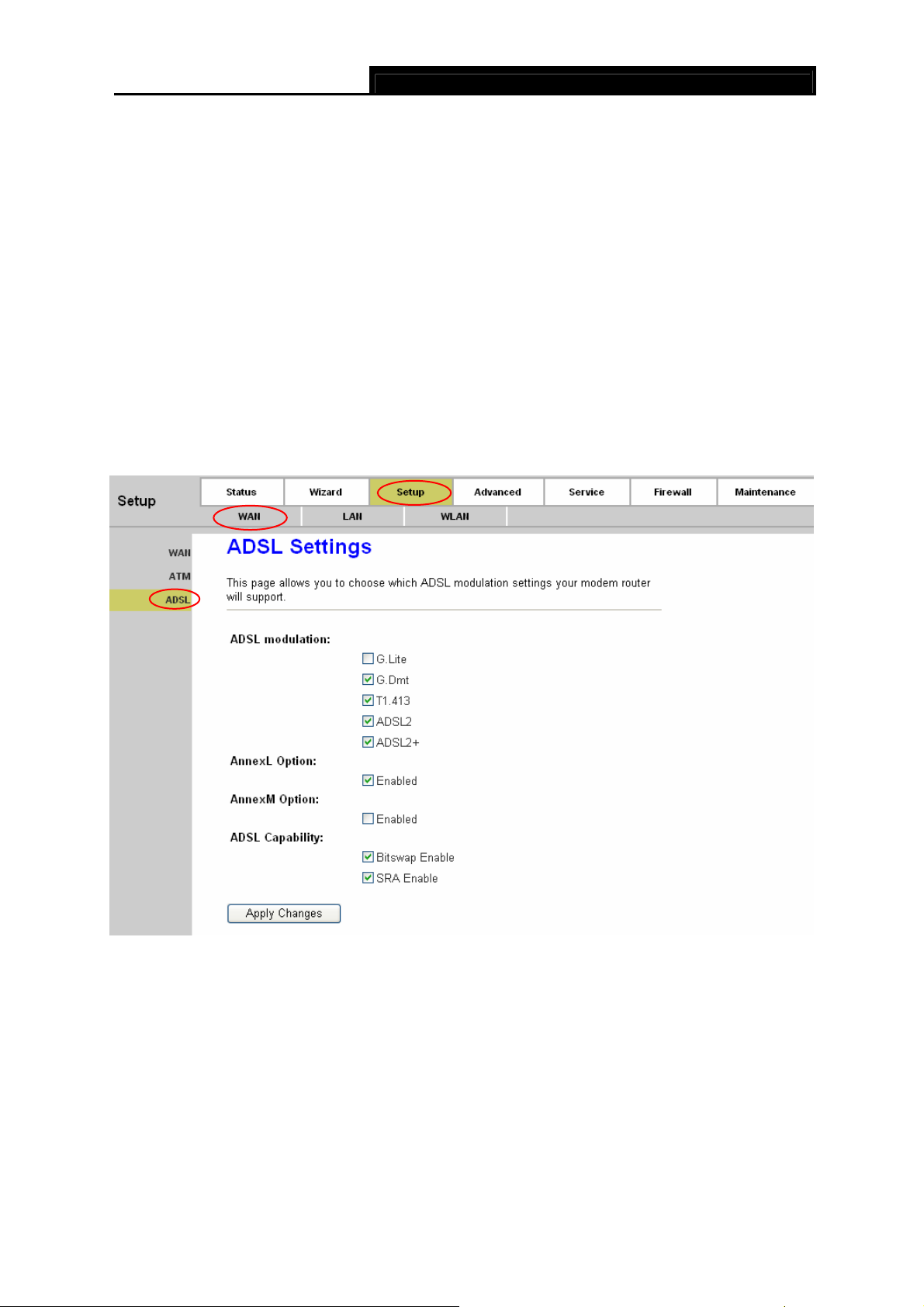
4.2.1.3 ADSL
Choose “Setup→WAN→ADSL” menu, you can configure some advanced parameters for your
ADSL Router in the next screen (shown in Figure 4-4).
Figure 4-6
After configuration, click Apply Changes button to save your changes.
Note:
)
After configuration, you need to click the Save button appeared on the left panel so that your
configuration can still take effect after the Router reboots.
22
TD851W 150Mbps Wireless N ADSL2+ Modem Router User Guide
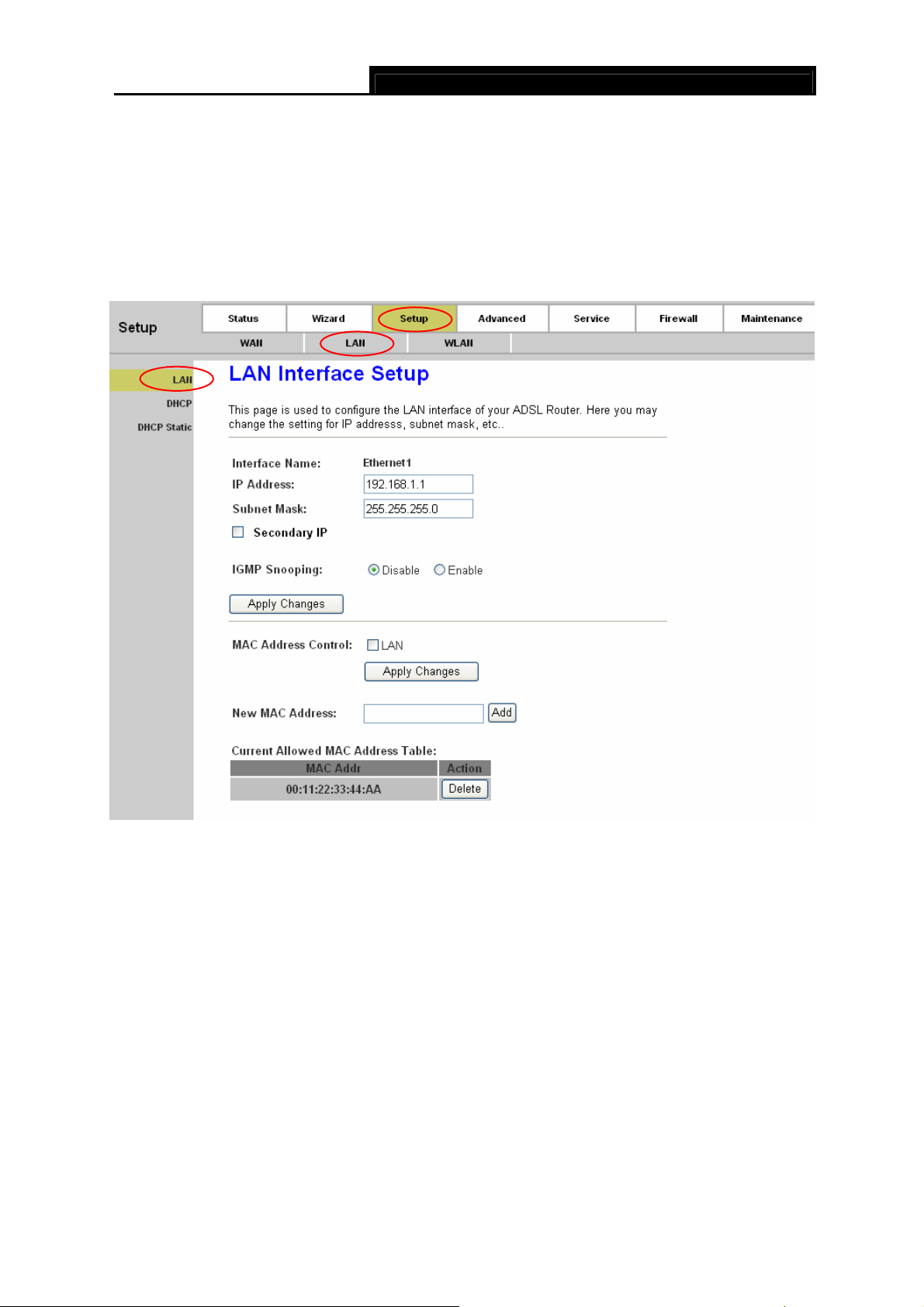
4.2.2 LAN
4.2.2.1 LAN
Choose “Setup→LAN→LAN” menu, and you will see the LAN Interface Setup screen (shown in
Figure 4-7). Here you can change IP address, subnet mask and other parameters for LAN
interface.
Figure 4-7
¾ Interface Name: Displays the name of the LAN interface for the device.
• IP Address: The Router’s local IP Address. You can access to the Web-based Utility via
the IP Address, the default value is 192.168.1.1. You can change the IP address if
needed. The LAN IP address is private to your internal network and cannot be seen on
the Internet.
• Subnet Mask: The subnet mask of the ADSL Router’s LAN interface. The default value
is 255.255.255.0.
¾ Secondary IP: If you enable the “Secondary IP”, you should configure another IP address
and subnet mask for the LAN interface.
¾ IGMP Snooping: You can enable or disable the IGMP Snooping function according to your
needs.
23

¾ MAC Address Control: The router supports the MAC address control on Ethernet port.
Select the LAN interface on which you want to run MAC Address Control. Click the Apply
Changes button to make the configuration take effect. For example, if you enable the MAC
address control on “LAN1”, then the traffic from interface “LAN1” will be flowed only when its
MAC address matches the Current Allowed MAC Address Table, otherwise the traffic will
be dropped by the router.
¾ New MAC Address: This field allows you to add a new MAC address to the Current Allowed
MAC Address Table. To add a new MAC address, enter the MAC address and then click
Add button.
¾ Current Allowed MAC Address Table: Displays the current allowed MAC address. Click the
Delete button and then the corresponding MAC address will be deleted.
After configuration, click Apply Changes button to save your changes.
Note:
)
After configuration, you need to click the Save button appeared on the left panel so that your
configuration can still take effect after the Router reboots.
TD851W 150Mbps Wireless N ADSL2+ Modem Router User Guide
4.2.2.2 DHCP
Choose “Setup→LAN→DHCP” menu, and then you will see the DHCP Mode screen (shown in
Figure 4-7). Here you can configure the DHCP mode of your ADSL Router as None, DHCP Relay
or DHCP Server. DHCP stands for Dynamic Host Control Protocol. The DHCP Server gives out IP
addresses when a device is booting up and request an IP address to be logged on to the network.
24
Loading...