


TD-8840T
ADSL2+ Modem Router
Rev: 4.0.0 1910010648
COPYRIGHT & TRADEMARKS
Specifications are subject to change without notice.  is a registered trademark of TP-LINK TECHNOLOGIES CO., LTD. Other brands and product names are trademarks or registered trademarks of their respective holders.
No part of the specifications may be reproduced in any form or by any means or used to make any derivative such as translation, transformation, or adaptation without permission from TP-LINK TECHNOLOGIES CO., LTD. Copyright © 2012 TP-LINK TECHNOLOGIES CO., LTD. All rights reserved.
http://www.tp-link.com

FCC STATEMENT
This equipment has been tested and found to comply with the limits for a Class B digital device, pursuant to part 15 of the FCC Rules. These limits are designed to provide reasonable protection against harmful interference in a residential installation. This equipment generates, uses and can radiate radio frequency energy and, if not installed and used in accordance with the instructions, may cause harmful interference to radio communications. However, there is no guarantee that interference will not occur in a particular installation. If this equipment does cause harmful interference to radio or television reception, which can be determined by turning the equipment off and on, the user is encouraged to try to correct the interference by one or more of the following measures:
•Reorient or relocate the receiving antenna.
•Increase the separation between the equipment and receiver.
•Connect the equipment into an outlet on a circuit different from that to which the receiver is connected.
•Consult the dealer or an experienced radio/ TV technician for help.
This device complies with part 15 of the FCC Rules. Operation is subject to the following two conditions:
1)This device may not cause harmful interference.
2)This device must accept any interference received, including interference that may cause undesired operation.
Any changes or modifications not expressly approved by the party responsible for compliance could void the user’s authority to operate the equipment.
CE Mark Warning
This is a class B product. In a domestic environment, this product may cause radio interference, in which case the user may be required to take adequate measures.
Продукт сертифіковано згідно с правилами системи УкрСЕПРО на відповідність вимогам нормативних документів та вимогам, що передбачені чинними законодавчими актами України

TP-LINK TECHNOLOGIES CO., LTD
DECLARATION OF CONFORMITY
For the following equipment:
Product Description: ADSL2+ Modem Router
Model No.: TD-8840T
Trademark: TP-LINK
We declare under our own responsibility that the above products satisfy all the technical regulations applicable to the product within the scope of Council Directives:
Directives 2004 / 108 / EC, Directives 2006 / 95 / EC, Directives 2011/65/EU
The above product is in conformity with the following standards or other normative documents
EN 55022:2010
EN 55024:2010
EN 61000-3-2:2006+A1:2009+A2:2009
EN 61000-3-3:2008
EN60950-1:2006+A11 2009+A1:2010+A12:2011
The product carries the CE Mark:
Person is responsible for marking this declaration:
Yang Hongliang
Product Manager of International Business
Date of issue: 2012
TP-LINK TECHNOLOGIES CO., LTD
Building 24 (floors 1, 3, 4, 5), and 28 (floors 1-4) Central Science and Technology Park,
Shennan Rd, Nanshan, Shenzhen, China
|
CONTENTS |
|
Package Contents .................................................................................................... |
1 |
|
Chapter 1. Product Overview................................................................................... |
2 |
|
1.1 |
Overview of the Modem Router ...................................................................................... |
2 |
1.2 |
Main Features................................................................................................................. |
3 |
1.3 |
Panel Layout................................................................................................................... |
4 |
|
1.3.1 The Front Panel ................................................................................................................... |
4 |
|
1.3.2 The Back Panel.................................................................................................................... |
4 |
Chapter 2. Connecting the Modem Router ............................................................. |
6 |
|
2.1 |
Installation Environment ................................................................................................. |
6 |
2.2 |
Connecting the Modem Router....................................................................................... |
7 |
Chapter 3. Quick Installation Guide ........................................................................ |
8 |
|
3.1 |
Configuring the PC ......................................................................................................... |
8 |
3.2 |
Login ............................................................................................................................. |
11 |
Chapter 4. Configuring the Modem Router .......................................................... |
15 |
|
4.1 |
Login ............................................................................................................................. |
15 |
4.2 |
Status............................................................................................................................ |
15 |
4.3 |
Quick Setup .................................................................................................................. |
16 |
4.4 |
Network......................................................................................................................... |
16 |
|
4.4.1 WAN Settings..................................................................................................................... |
17 |
|
4.4.2 Interface Grouping ............................................................................................................. |
25 |
|
4.4.3 LAN Settings ...................................................................................................................... |
26 |
|
4.4.4 MAC Clone......................................................................................................................... |
27 |
|
4.4.5 ALG Settings...................................................................................................................... |
28 |
|
4.4.6 DSL Settings ...................................................................................................................... |
29 |
4.5 |
DHCP Server ................................................................................................................ |
29 |
|
4.5.1 DHCP Settings................................................................................................................... |
29 |
|
4.5.2 Clients List.......................................................................................................................... |
31 |
|
4.5.3 Address Reservation.......................................................................................................... |
31 |
|
4.5.4 Conditional Pool................................................................................................................. |
32 |
4.6 |
Route Settings .............................................................................................................. |
33 |
|
4.6.1 Default Gateway................................................................................................................. |
34 |
|
4.6.2 Static Route........................................................................................................................ |
34 |
|
4.6.3 |
RIP Settings ....................................................................................................................... |
35 |
4.7 |
Forwarding.................................................................................................................... |
36 |
|
|
4.7.1 |
Virtual Servers.................................................................................................................... |
36 |
|
4.7.2 |
Port Triggering ................................................................................................................... |
37 |
|
4.7.3 DMZ ................................................................................................................................... |
39 |
|
|
4.7.4 UPnP.................................................................................................................................. |
40 |
|
4.8 |
Parent Control............................................................................................................... |
40 |
|
4.9 |
Firewall ......................................................................................................................... |
42 |
|
|
4.9.1 Rule.................................................................................................................................... |
42 |
|
|
4.9.2 LAN Host............................................................................................................................ |
43 |
|
|
4.9.3 WAN Host .......................................................................................................................... |
44 |
|
|
4.9.4 Schedule ............................................................................................................................ |
45 |
|
|
4.9.5 DDoS.................................................................................................................................. |
46 |
|
4.10 |
Bandwidth Control ........................................................................................................ |
48 |
|
4.11 |
IP&MAC Binding ........................................................................................................... |
49 |
|
|
4.11.1 Binding Settings................................................................................................................ |
49 |
|
|
4.11.2 ARP List............................................................................................................................ |
50 |
|
4.12 |
Dynamic DNS ............................................................................................................... |
51 |
|
4.13 |
Diagnostic ..................................................................................................................... |
51 |
|
4.14 |
System Tools ................................................................................................................ |
52 |
|
|
4.14.1 System Log....................................................................................................................... |
52 |
|
|
4.14.2 Time Settings.................................................................................................................... |
53 |
|
|
4.14.3 Manage Control ................................................................................................................ |
54 |
|
|
4.14.4 CWMP Settings ................................................................................................................ |
55 |
|
|
4.14.5 SNMP Settings ................................................................................................................. |
56 |
|
|
4.14.6 Backup & Restore............................................................................................................. |
57 |
|
|
4.14.7 Factory Defaults................................................................................................................ |
57 |
|
|
4.14.8 Firmware Upgrade............................................................................................................ |
58 |
|
|
4.14.9 Reboot .............................................................................................................................. |
59 |
|
|
4.14.10 Statistics........................................................................................................................ |
59 |
|
Appendix A: Specifications ................................................................................... |
61 |
||
Appendix B: Troubleshooting ............................................................................... |
62 |
||
Appendix C: Technical Support ............................................................................ |
71 |
||

TD-8840T ADSL2+ Modem Router User Guide
Package Contents
The following contents should be found in your package:
¾One TD-8840T ADSL2+ Modem Router
¾One Power Adapter for TD-8840T ADSL2+ Modem Router
¾Quick Installation Guide
¾One RJ45 cable
¾Two RJ11 cables
¾One ADSL splitter
¾One Resource CD for TD-8840T ADSL2+ Modem Router, including:
•This User Guide
•Other Helpful Information
) Note:
Make sure that the package contains the above items. If any of the listed items are damaged or missing, please contact your distributor.
1

TD-8840T ADSL2+ Modem Router User Guide
Chapter 1. Product Overview
Thank you for choosing the TD-8840T ADSL2+ Modem Router.
1.1 Overview of the Modem Router
The device is designed to provide a simple and cost-effective ADSL Internet connection for a private Ethernet network.
The TD-8840T ADSL2+ Modem Router connects to an Ethernet LAN or computers via standard Ethernet ports. The ADSL connection is made using ordinary telephone line with standard connectors. Multiple workstations can be networked and connected to the Internet using a single Wide Area Network (WAN) interface and single global IP address. The advanced security enhancements, IP/MAC Filter, Application Filter and URL Filter can help to protect your network from potentially devastating intrusions by malicious agents from the outside of your network.
Quick Start of the Web-based Utility is supplied and friendly help messages are provided for the configuration. Network and Router management is done through the Web-based Utility which can be accessed through local Ethernet using any web browser.
ADSL
The TD-8840T ADSL2+ Modem Router supports full-rate ADSL2+ connectivity conforming to the ITU and ANSI specifications. In addition to the basic DMT physical layer functions, the ADSL2+ PHY supports dual latency ADSL2+ framing (fast and interleaved) and the I.432 ATM Physical Layer.
2

TD-8840T ADSL2+ Modem Router User Guide
1.2 Main Features
¾4 10/100M RJ45 LAN ports (Auto MDI/MDIX), 1 RJ11 port.
¾Downstream data rates up to 24Mbps, upstream data rates up to 3.5Mbps With Annex M enabled .
¾Supports long transfers, the max line length can reach to 6.5Km.
¾Supports remote configuration and management through SNMP and CWMP.
¾Supports PPPoE, it allows connecting the internet on demand and disconnecting from the Internet when idle.
¾Quick response semi-conductive surge protection circuit, provides reliable ESD and surge-protect function.
¾High speed and asymmetrical data transmit mode, provides safe and exclusive bandwidth.
¾Supports All ADSL industrial standards.
¾Compatible with all mainstreams DSLAM (CO).
¾Provides integrated access of internet and route function which face to SOHO user.
¾Real-time Configuration and device monitoring.
¾Supports Multiple PVC (Permanent Virtual Circuit).
¾Built-in DHCP server.
¾Built-in firewall, supports IP/MAC filter, Application filter and URL filter.
¾Supports Virtual Server, DMZ host and IP Address Mapping.
¾Supports Dynamic DNS, UPnP and Static Routing.
¾Supports system log and flow Statistics.
¾Supports firmware upgrade and Web management.
3
TD-8840T ADSL2+ Modem Router User Guide
1.3 Panel Layout
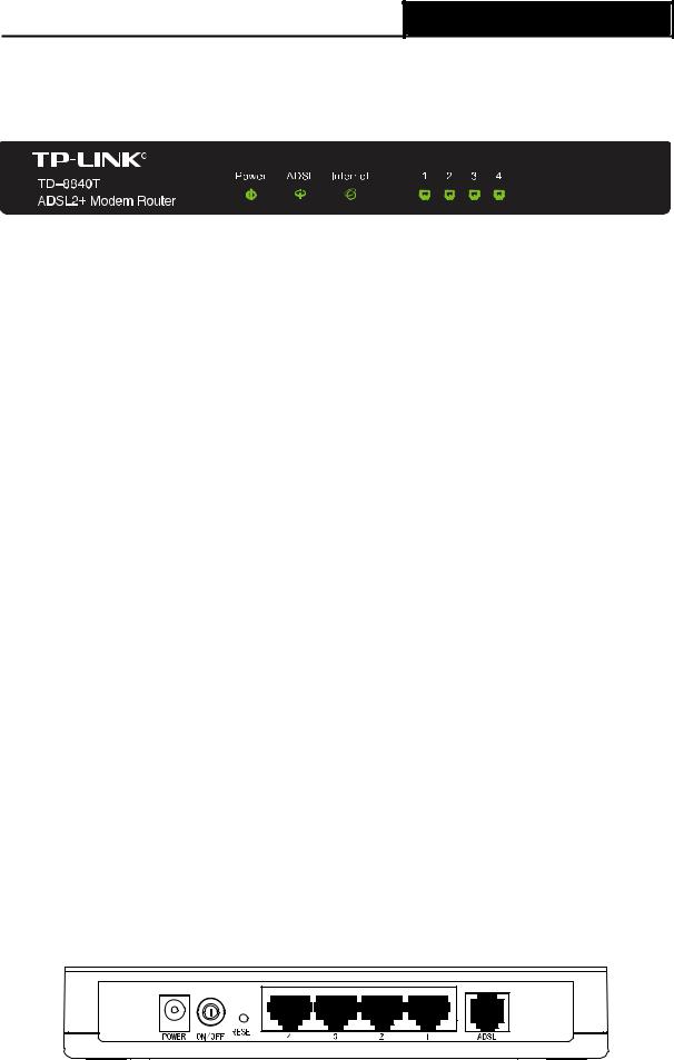
1.3.1 The Front Panel
Figure 1-1
The Router’s LEDs are located on the front panel (View from left to right). They indicate the device’s working status. For details, please refer to LED Explanation.
LED Explanation:
|
Name |
|
Status |
|
Indication |
|
|
|
|
|
|
|
Power |
|
On |
|
Power is on. |
|
|
|
|
|
|
|
|
Off |
Power is off. |
||
|
|
|
|||
|
|
|
|
|
|
|
|
|
On |
|
The ADSL port is linked up. |
|
ADSL |
|
|
|
|
|
|
Flash |
The ADSL negotiation is in progress. |
||
|
|
|
|
|
|
|
|
|
Off |
The ADSL port is linked down. |
|
|
|
|
|
|
|
|
|
|
On |
|
A successful PPP connection has been built. |
|
|
|
|
|
|
|
Internet |
|
Flash |
Data is being transferred over the Internet. |
|
|
|
|
|
|
|
|
|
|
Off |
|
There is no successful PPP connection or the Router works |
|
|
|
|
on Bridge mode. |
|
|
|
|
|
|
|
|
|
|
|
|
|
|
|
|
On |
|
There is a successful connection on the corresponding 1~4 |
|
|
|
|
(LAN) port but no activity. |
|
|
|
|
|
|
|
|
1~4 (LAN) |
|
|
|
|
|
|
Off |
|
There is no connection on the corresponding 1~4 (LAN) port |
|
|
|
|
|
or the connection is abnormal. |
|
|
|
|
|
|
|
|
|
|
|
|
|
|
|
|
Flash |
Data is being transferred over the 1~4 (LAN) port |
|
|
|
|
|
|
|
1.3.2 The Back Panel
The Router's ports, where the cables are connected, and RESET button are located on the back
Figure 1-2
4
TD-8840T ADSL2+ Modem Router User Guide
¾POWER: The Power socket is where the power adapter connects to.
¾ON/OFF: The switch for the power.
¾RESET: There are two ways to reset the Router's factory defaults.
Method one: With the Router powered on, use a pin to press and hold the Reset button for at least 5 seconds. And the Router will reboot to its factory default settings.
Method two Restore the default setting from “Maintenance-SysRestart” of the Router's Web-based Utility.
¾LAN (4~1): Through the port, you can connect the Router to your PC or the other Ethernet network devices.
¾ADSL: Through the port, you can connect the Router to the splitter or to the Internet directly.
5

TD-8840T ADSL2+ Modem Router User Guide
Chapter 2. Connecting the Modem Router
2.1 Installation Environment
¾The Product should not be located where it will be exposed to moisture or excessive heat.
¾Place the Router in a location where it can be connected to the various devices as well as to a power source.
¾Make sure the cables and power cord are placed safely out of the way so they do not create a tripping hazard.
¾The Router can be placed on a shelf or desktop.
¾Keep away from the strong electromagnetic radiation and the device of electromagnetic sensitive.
Figure 2-1
) Note:
The diameter of the screw, 2.0mm<D<8.0mm, and the distance of two screws is 129.61mm. The screw that project from the wall need around 4mm based, and the length of the screw need to be at least 20mm to withstand the weight of the product.
6
TD-8840T ADSL2+ Modem Router User Guide
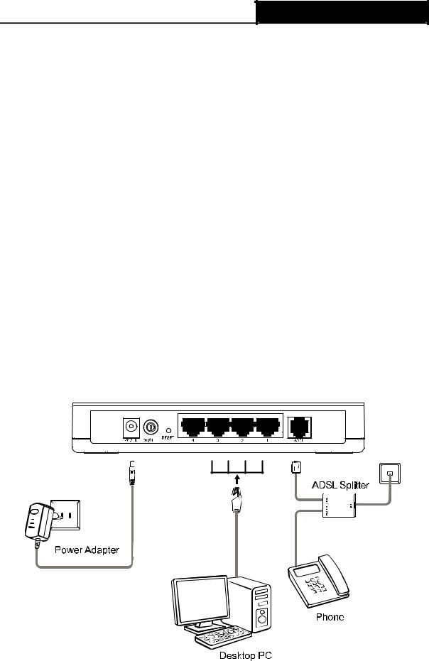
2.2 Connecting the Modem Router
Before installing the device, please make sure your broadband service provided by your ISP is available. If there is any problem, please contact your ISP. Before cable connection, cut off the power supply and keep your hands dry. You can follow the steps below to install it.
Step 1: Connect the ADSL Line.
Method one: Plug one end of the twisted-pair ADSL cable into the ADSL port on the rear panel of , and insert the other end into the wall socket.
Method two You can use a separate splitter. External splitter can divide the data and voice, and then you can access the Internet and make calls at the same time. The external splitter has three ports:
•LINE: Connect to the wall jack
•PHONE: Connect to the phone sets
•MODEM: Connect to the ADSL port of
Plug one end of the twisted-pair ADSL cable into the ADSL port on the rear panel of . Connect the other end to the MODEM port of the external splitter.
Step 2: Connect the Ethernet cable. Attach one end of a network cable to your computer’s Ethernet port or a regular hub/switch port, and the other end to the LAN port on the Modem Router.
Step 3: Power on the computers and LAN devices.
Step 4: Attach the power adapter. Connect the power adapter to the power connector on the rear of the device and plug in the adapter to a electrical outlet or power extension. The electrical outlet shall be installed near the device and shall be easily accessible.
Figure 2-2
7
TD-8840T ADSL2+ Modem Router User Guide
Chapter 3. Quick Installation Guide
3.1 Configuring the PC
After you directly connect your PC to the Modem Router or connect your adapter to a Hub/Switch which has connected to the Modem Router, you need to configure your PC’s IP address. Follow the steps below to configure it.
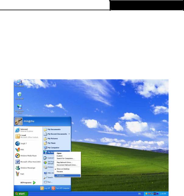
Step 1: Click the Start menu on your desktop, right click My Network Places, and then select Properties (shown in Figure 3-1).
Figure 3-1
Step 2: Right click Local Area Connection (LAN), and then select Properties.
8

TD-8840T ADSL2+ Modem Router User Guide
Figure 3-2
Step 3: Select General tab, highlight Internet Protocol (TCP/IP), and then click the Properties button.
Figure 3-3
9
TD-8840T ADSL2+ Modem Router User Guide
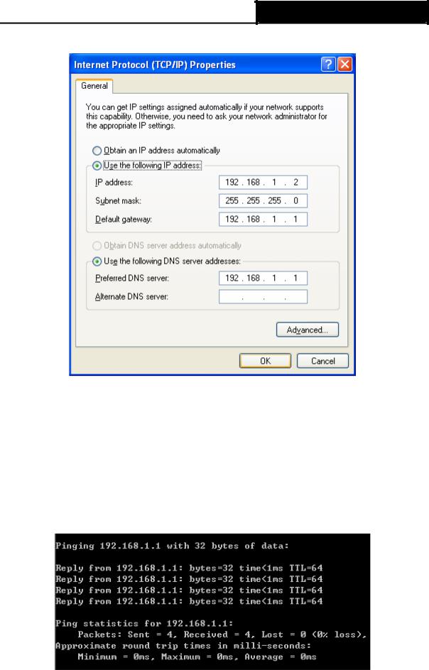
Step 4: Configure the IP address as Figure 3-4 shows. After that, click OK.
Figure 3-4
) Note:
You can configure the PC to get an IP address automatically, select “Obtain an IP address automatically” and “Obtain DNS server address automatically” in the screen above.
Now, you can run the Ping command in the command prompt to verify the network connection. Please click the Start menu on your desktop, select run tab, type cmd or command in the field and press Enter. Type ping 192.168.1.1 on the next screen, and then press Enter.
If the result displayed is similar to the screen below, the connection between your PC and the Modem Router has been established.
Figure 3-5
10
TD-8840T ADSL2+ Modem Router User Guide
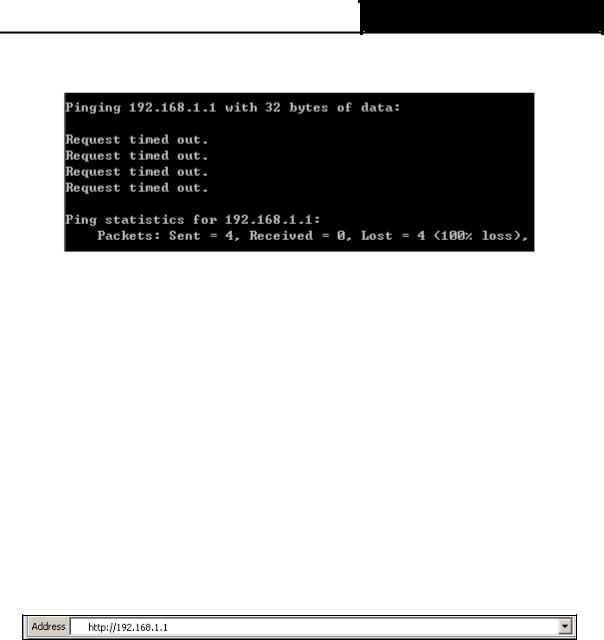
If the result displayed is similar to the screen shown below, it means that your PC has not connected to the Modem Router.
Figure 3-6
You can check it following the steps below:
1)Is the connection between your PC and the Modem Router correct?
The LEDs of LAN port which you link to the device and the LEDs on your PC's adapter should be lit.
2)Is the TCP/IP configuration for your PC correct?
If the Router's IP address is 192.168.1.1, your PC's IP address must be within the range of 192.168.1.2 ~ 192.168.1.254.
3.2 Login
Once your host PC is properly configured, please proceed as follows to use the Web-based Utility: Start your web browser and type the private IP address of the Router in the URL field:
192.168.1.1.
1.To access the configuration utility, open a web-browser and type the default address http://192.168.1.1 in the address field of the browser.
Figure 3-7
After a moment, a login window will appear, similar to the Figure 3-8. Enter admin for the User Name and Password, both in lower case letters. Then click the OK button or press the
Enter key.
11

TD-8840T ADSL2+ Modem Router User Guide
Figure 3-8
) Note:
1)Do not mix up the user name and password with your ADSL account user name and password which are needed for PPP connections.
2)If the above screen does not pop up, it means that your Web-browser has been set to a proxy. Go to Tools menu→Internet Options→Connections→LAN Settings, in the screen that appears, cancel the Using Proxy checkbox, and click OK to finish it.
2.After your successful login, you will see the Login screen as shown in Figure 3-9. Click Quick Setup menu to access Quick Setup Wizard.
12

TD-8840T ADSL2+ Modem Router User Guide
Figure 3-9
3.Change the VPI or VCI values which are used to define a unique path for your connection. If you have been given specific settings for this to configuration, type in the correct values assigned by your ISP. Click Next.
Figure 3-10
4.Here we select PPPoE WAN Link Type for example, enter the Username, Password and Confirm Password given by your ISP, and then click Next.
13
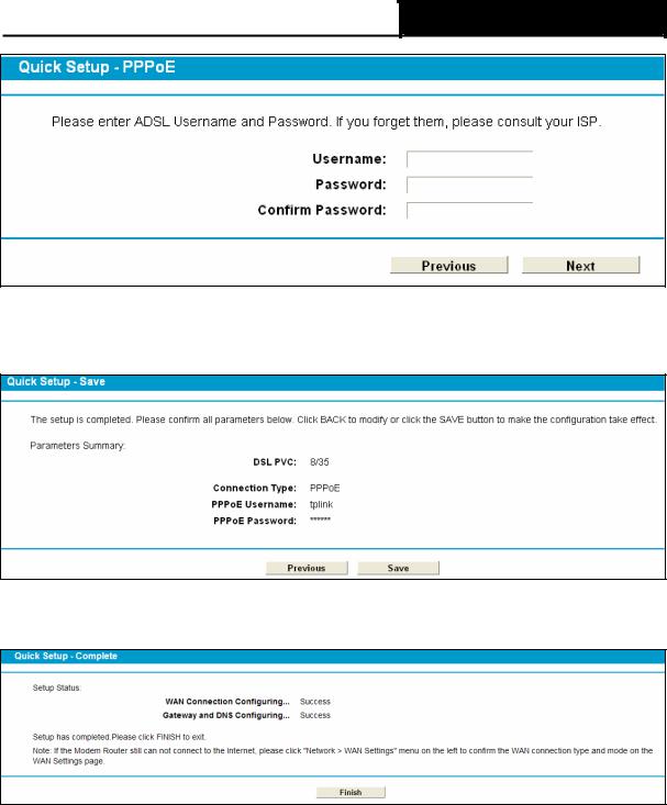
TD-8840T ADSL2+ Modem Router User Guide
Figure 3-11
5.On this page, please confirm all parameters. Click Previous to modify or click the Save button to make the configuration take effect.
Figure 3-12
6.You will see the Complete screen below, click Finish to complete these settings.
Figure 3-13
14
TD-8840T ADSL2+ Modem Router User Guide
Chapter 4. Configuring the Modem Router
This chapter will show each Web page's key function and the configuration way.
4.1 Login
After your successful login, you will see the fifteen main menus on the left of the Web-based utility. On the right, there are the corresponding explanations and instructions.
The detailed explanations for each Web page’s key function are listed below.
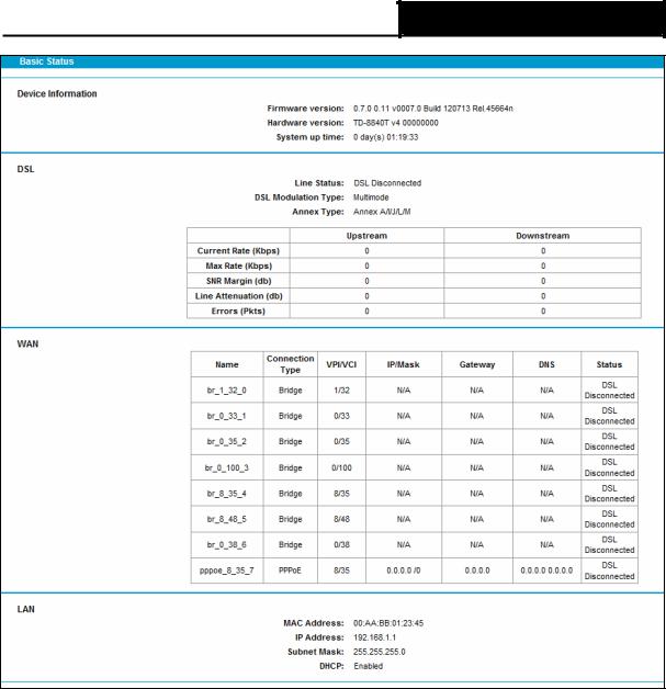
4.2 Status
Choose “Status”, you can see the corresponding information about Device Information, DSL,
WAN and LAN.
15
TD-8840T ADSL2+ Modem Router User Guide
Figure 4-1
4.3 Quick Setup
Please refer to Section 3.2 Login.
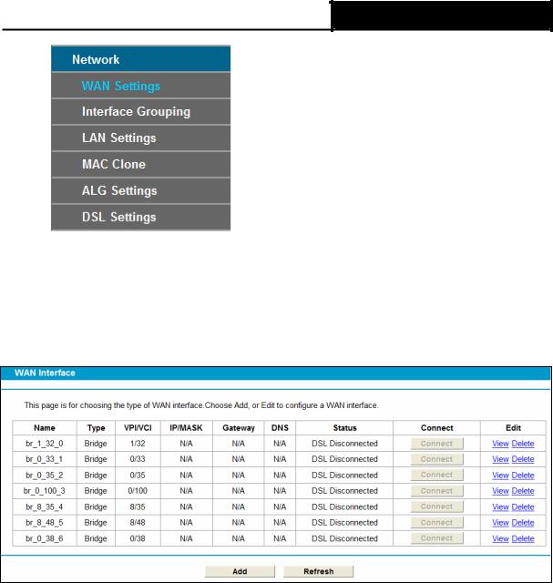
4.4 Network
Choose “Network”, there are many submenus under the main menu. Click any one of them, and you will be able to configure the corresponding function.
16
TD-8840T ADSL2+ Modem Router User Guide
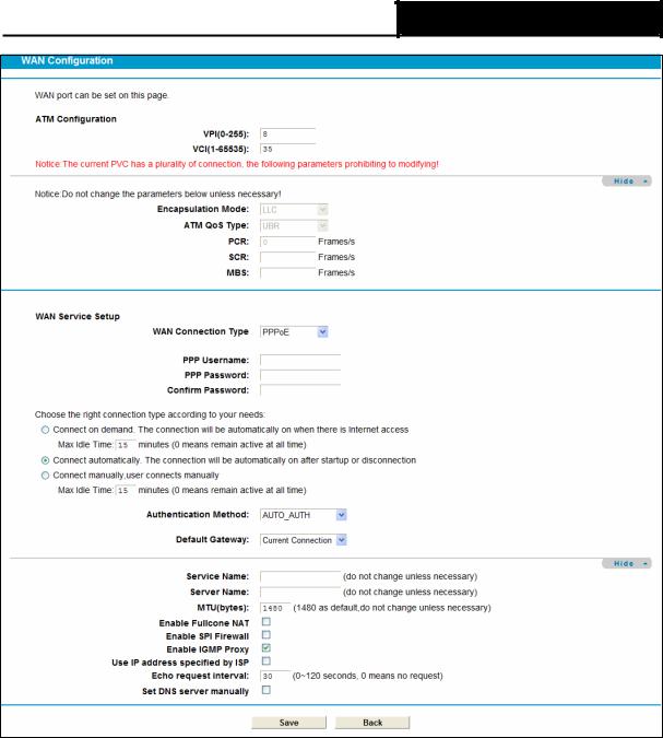
4.4.1 WAN Settings
Choose “Network”Æ“WAN Settings”, and you will see the WAN Port Information Table in the screen similar to Figure 4-2, which describes the WAN port settings and the relevant manipulation to each interface. There are five different configurations for the connection types, which are Static IP, Dynamic IP, PPPoE, IPoA, and Bridge. You can select the corresponding types according to your needs.
Figure 4-2
Click Add to add a new entry, you can configure the parameters for ATM and WAN Service in the next screen (shown in Figure 4-3).
17
TD-8840T ADSL2+ Modem Router User Guide
Figure 4-3
4.4.1.1 Static IP
Select this option if your ISP provides static IP information to you. You should set static IP address, IP subnet mask, and gateway address in the screen below.
18
 Loading...