


 Loading...
TL-MR3420
3G/4G Wireless N Router
Rev: 2.0.0 1910010676
COPYRIGHT & TRADEMARKS
Specifications are subject to change without notice.  is a registered trademark of TP-LINK TECHNOLOGIES CO., LTD. Other brands and product names are trademarks or registered trademarks of their respective holders.
No part of the specifications may be reproduced in any form or by any means or used to make any derivative such as translation, transformation, or adaptation without permission from TP-LINK TECHNOLOGIES CO., LTD. Copyright © 2012 TP-LINK TECHNOLOGIES CO., LTD. All rights reserved.
http://www.tp-link.com

FCC STATEMENT
This equipment has been tested and found to comply with the limits for a Class B digital device, pursuant to part 15 of the FCC Rules. These limits are designed to provide reasonable protection against harmful interference in a residential installation. This equipment generates, uses and can radiate radio frequency energy and, if not installed and used in accordance with the instructions, may cause harmful interference to radio communications. However, there is no guarantee that interference will not occur in a particular installation. If this equipment does cause harmful interference to radio or television reception, which can be determined by turning the equipment off and on, the user is encouraged to try to correct the interference by one or more of the following measures:
Reorient or relocate the receiving antenna.
Increase the separation between the equipment and receiver.
Connect the equipment into an outlet on a circuit different from that to which the receiver is connected.
Consult the dealer or an experienced radio/ TV technician for help.
This device complies with part 15 of the FCC Rules. Operation is subject to the following two conditions:
This device may not cause harmful interference.
This device must accept any interference received, including interference that may cause
undesired operation.
Any changes or modifications not expressly approved by the party responsible for compliance could void the user’s authority to operate the equipment.
Note: The manufacturer is not responsible for any radio or TV interference caused by unauthorized modifications to this equipment. Such modifications could void the user’s authority to operate the equipment.
FCC RF Radiation Exposure Statement:
This equipment complies with FCC RF radiation exposure limits set forth for an uncontrolled environment. This device and its antenna must not be co-located or operating in conjunction with any other antenna or transmitter.
“To comply with FCC RF exposure compliance requirements, this grant is applicable to only Mobile Configurations. The antennas used for this transmitter must be installed to provide a separation distance of at least 20 cm from all persons and must not be co-located or operating in conjunction with any other antenna or transmitter.”

CE Mark Warning
This is a class B product. In a domestic environment, this product may cause radio interference, in which case the user may be required to take adequate measures.
National Restrictions
This device is intended for home and office use in all EU countries (and other countries following the EU directive 1999/5/EC) without any limitation except for the countries mentioned below:
Country |
Restriction |
Reason/remark |
|
Bulgaria |
None |
General authorization required for outdoor use and |
|
public service |
|||
|
|
||
|
|
|
|
|
Outdoor use limited to |
Military Radiolocation use. Refarming of the 2.4 GHz |
|
France |
10 mW e.i.r.p. within |
band has been ongoing in recent years to allow current |
|
the band 2454-2483.5 |
relaxed regulation. Full implementation planned 2012 |
||
|
|||
|
MHz |
|
|
|
|
|
|
Italy |
None |
If used outside of own premises, general authorization is |
|
required |
|||
|
|
||
|
|
|
|
Luxembourg |
None |
General authorization required for network and service |
|
supply(not for spectrum) |
|||
|
|
||
|
|
|
|
Norway |
Implemented |
This subsection does not apply for the geographical area |
|
within a radius of 20 km from the centre of Ny-Ålesund |
|||
|
|
||
|
|
|
|
Russian Federation |
None |
Only for indoor applications |
|
|
|
|
Note: Please don’t use the product outdoors in France.
This device has been designed to operate with the antennas listed below, and having a maximum gain of 5 dBi. Antennas not included in this list or having a gain greater than 5 dBi are strictly prohibited for use with this device. The required antenna impedance is 50 ohms.
To reduce potential radio interference to other users, the antenna type and its gain should be so chosen that the equivalent isotropically radiated power (e.i.r.p.) is not more than that permitted for successful communication.”
Industry Canada Statement:
This device complies with RSS-210 of the Industry Canada Rules. Operation is subject to the following two conditions:
(1)This device may not cause harmful interference, and
(2)This device must accept any interference received, including interference that may cause undesired operation.

IMPORTANT NOTE: Radiation Exposure Statement:
This equipment complies with Canada radiation exposure limits set forth for an uncontrolled environment. This equipment should be installed and operated with minimum distance 20cm between the radiator & your body.
Ce dispositif est conforme à la norme CNR-210 d’Industrie Canada applicable aux appareils radio exempts de licence. Son fonctionnement est sujet aux deux conditions suivantes:
(1)Le dispositif ne doit pas produire de brouillage préjudiciable, et
(2)Ce dispositif doit accepter tout brouillage reçu,y compris un brouillage susceptible de provoquer un fonctionnement indésirable.
NOTE IMPORTANTE:
Déclaration d’exposition aux radiations:
Cet équipement est conforme aux limites d’exposition aux rayonnements IC établies pour un environnement non contrôlé. Cet équipement doit être installé et utilisé avec un minimum de 20 cm de distance entre la source de rayonnement et votre corps.
Korea Warning Statements:
.
NCC Notice:
機須忍受合法通信或工業、科學及醫療用電波輻射性電機設備之干擾。
Продукт сертифіковано згідно с правилами системи УкрСЕПРО на відповідність вимогам нормативних документів та вимогам, що передбачені чинними законодавчими актами України.
TP-LINK TECHNOLOGIES CO., LTD
DECLARATION OF CONFORMITY
For the following equipment:
Product Description: 3G/4G Wireless N Router
Model No.: TL-MR3420 Trademark: TP-LINK
We declare under our own responsibility that the above products satisfy all the technical regulations applicable to the product within the scope of Council Directives:
Directives 1999/5/EC, Directives 2004/108/EC, Directives 2006/95/EC, Directives 1999/519/EC, Directives 2011/65/EU
The above product is in conformity with the following standards or other normative documents
ETSI EN 300 328 V1.7.1: 2006
ETSI EN 301 489-1 V1.8.1:2008& ETSI EN 301 489-17 V2.1.1:2009 EN 55022:2010
EN 55024:2010
EN 61000-3-2:2006+A1:2009+A2:2009 EN 61000-3-3:2008
EN60950-1:2006+A11 2009+A1:2010+A12:2011
EN62311:2008
The product carries the CE Mark:
Person is responsible for marking this declaration:
Yang Hongliang
Product Manager of International Business
Date of issue: 2012
TP-LINK TECHNOLOGIES CO., LTD.
Building 24 (floors 1, 3, 4, 5), and 28 (floors 1-4) Central Science and Technology Park,
Shennan Rd, Nanshan, Shenzhen, China
|
|
CONTENTS |
|
Package Contents....................................................................................................... |
1 |
||
Chapter 1. |
Introduction......................................................................................... |
2 |
|
1.1 |
Overview of the Router................................................................................................. |
2 |
|
1.2 |
Conventions ................................................................................................................. |
2 |
|
1.3 |
Main Features .............................................................................................................. |
2 |
|
1.4 |
Panel Layout ................................................................................................................ |
3 |
|
|
1.4.1 |
The Front Panel................................................................................................ |
3 |
|
1.4.2 |
The Rear Panel ................................................................................................ |
4 |
|
1.4.3 |
The Side Panel ................................................................................................. |
4 |
Chapter 2. |
Connecting the Router ....................................................................... |
5 |
|
2.1 |
System Requirements .................................................................................................. |
5 |
|
2.2 |
Installation Environment Requirements........................................................................ |
5 |
|
2.3 |
Connecting the Router ................................................................................................. |
5 |
|
Chapter 3. |
Quick Installation Guide..................................................................... |
7 |
|
3.1 |
TCP/IP Configuration ................................................................................................... |
7 |
|
3.2 |
Quick Installation Guide ............................................................................................... |
7 |
|
Chapter 4. |
Configuring the Router..................................................................... |
13 |
|
4.1 |
Login .......................................................................................................................... |
|
13 |
4.2 |
Status ......................................................................................................................... |
|
13 |
4.3 |
Quick Setup................................................................................................................ |
14 |
|
4.4 |
WPS ........................................................................................................................... |
|
14 |
4.5 |
Network ...................................................................................................................... |
21 |
|
|
4.5.1 |
Internet Access ............................................................................................... |
21 |
|
4.5.2 |
3G/4G ............................................................................................................. |
22 |
|
4.5.3 |
WAN ............................................................................................................... |
26 |
|
4.5.4 |
MAC Clone ..................................................................................................... |
35 |
|
4.5.5 |
LAN................................................................................................................. |
35 |
4.6 |
Wireless ..................................................................................................................... |
36 |
|
|
4.6.1 |
Wireless Settings............................................................................................ |
36 |
|
4.6.2 |
Wireless Security............................................................................................ |
38 |
|
4.6.3 |
Wireless MAC Filtering ................................................................................... |
41 |
|
4.6.4 |
Wireless Advanced ......................................................................................... |
43 |
|
4.6.5 |
Wireless Statistics........................................................................................... |
45 |
4.7 |
DHCP ......................................................................................................................... |
|
45 |
I
|
4.7.1 |
DHCP Settings ............................................................................................... |
46 |
|
4.7.2 |
DHCP Client List............................................................................................. |
47 |
|
4.7.3 |
Address Reservation ...................................................................................... |
47 |
4.8 |
Forwarding ................................................................................................................. |
48 |
|
|
4.8.1 |
Virtual Servers ................................................................................................ |
48 |
|
4.8.2 |
Port Triggering ................................................................................................ |
50 |
|
4.8.3 |
DMZ................................................................................................................ |
52 |
|
4.8.4 |
UPnP .............................................................................................................. |
53 |
4.9 |
Security ...................................................................................................................... |
54 |
|
|
4.9.1 |
Basic Security................................................................................................. |
54 |
|
4.9.2 |
Advanced Security.......................................................................................... |
55 |
|
4.9.3 |
Local Management ......................................................................................... |
57 |
|
4.9.4 |
Remote Management ..................................................................................... |
58 |
4.10 |
Parental Control ......................................................................................................... |
58 |
|
4.11 |
Access Control ........................................................................................................... |
61 |
|
|
4.11.1 |
Rule ................................................................................................................ |
62 |
|
4.11.2 |
Host ................................................................................................................ |
64 |
|
4.11.3 |
Target.............................................................................................................. |
65 |
|
4.11.4 |
Schedule......................................................................................................... |
67 |
4.12 Advanced Routing ...................................................................................................... |
68 |
||
|
4.12.1 |
Static Routing List........................................................................................... |
69 |
|
4.12.2 System Routing Table..................................................................................... |
70 |
|
4.13 Bandwidth Control ...................................................................................................... |
70 |
||
|
4.13.1 |
Control Settings .............................................................................................. |
70 |
|
4.13.2 |
Rule List.......................................................................................................... |
71 |
4.14 IP & MAC Binding....................................................................................................... |
72 |
||
|
4.14.1 |
Binding Settings.............................................................................................. |
72 |
|
4.14.2 ARP List.......................................................................................................... |
74 |
|
4.15 Dynamic DNS............................................................................................................. |
74 |
||
|
4.15.1 Comexe.cn DDNS .......................................................................................... |
74 |
|
|
4.15.2 Dyndns.org DDNS .......................................................................................... |
75 |
|
|
4.15.3 No-ip.com DDNS ............................................................................................ |
76 |
|
4.16 System Tools .............................................................................................................. |
77 |
||
|
4.16.1 |
Time Settings.................................................................................................. |
77 |
|
4.16.2 |
Diagnostic....................................................................................................... |
78 |
|
4.16.3 |
Firmware Upgrade.......................................................................................... |
80 |
|
4.16.4 |
Factory Defaults ............................................................................................. |
81 |
II
4.16.5 Backup & Restore........................................................................................... |
81 |
4.16.6 Reboot ............................................................................................................ |
82 |
4.16.7 Password........................................................................................................ |
82 |
4.16.8 System Log..................................................................................................... |
83 |
4.16.9 Statistics ......................................................................................................... |
85 |
Appendix A: FAQ....................................................................................................... |
87 |
Appendix B: Configuring the PCs ........................................................................... |
92 |
Appendix C: Specifications...................................................................................... |
96 |
Appendix D: Glossary .............................................................................................. |
97 |
Appendix E: Compatible 3G/4G USB Modem ......................................................... |
99 |
III

TL-MR3420 3G/4G Wireless N Router User Guide
Package Contents
The following items should be found in your package:
TL-MR3420 3G/4G Wireless N Router
DC Power Adapter for TL-MR3420 3G/4G Wireless N Router
Ethernet Cable
Quick Installation Guide
Resource CD for TL-MR3420 3G/4G Wireless N Router, including:
This Guide
Other Helpful Information
Note:
Make sure that the package contains the above items. If any of the listed items is damaged or missing, please contact with your distributor.
-1-
TL-MR3420 3G/4G Wireless N Router User Guide
Chapter 1.Introduction
1.1 Overview of the Router
TP-LINK understands the need for sharing the 3G/4G connection locally that benefits our end users. We realize the convenience with our latest wireless N 3G/4G Routers ----- they give you the freedom to quickly set up a stable and high speed wireless network, up to 300Mbps, on-the-go and share a 3G/4G connection. By connecting a USB Card to the Router, a Wi-Fi hotspot is instantly established allowing users to share a Internet connection anywhere 3G/4G coverage is available. So whether you’re on the train, camping, or at a construction site, you’ll have a reliable wireless connection to accommodate your networking needs.
3G/4G and WAN Broadband
The TL-MR3420 3G/4G Wireless N Router provides 3G/4G and WAN (xDSL, static IP, or dynamic IP) two kinds of broadband connections to get on the Internet, you can via the Internet no matter at home or outside on business. Automatic 3G/4G and WAN failover feature just provide nonstop internet connection.
Incredibly High Speed
TP-LINK 3G/4G Router provides up to 300Mbps, faster than that of traditional 11g products, surpasses 11G performance enabling the use of high bandwidth-consuming applications such as HD Videos.
Wi-fi Protected Setup
With just pressing on the 'WPS' button, the Router automatically establishes a WPA2 secure connection for solid security in under a minute.
1.2 Conventions
The Router or TL-MR3420 mentioned in this guide stands for TL-MR3420 3G/4G Wireless N Router without any explanation.
1.3 Main Features
One 10/100M Auto-Negotiation RJ45 WAN port, four 10/100M Auto-Negotiation RJ45 LAN ports, supporting Auto MDI/MDIX
Compatible with LTE/HSPA+/HSUPA/HSDPA/UMTS/EVDO USB modem
Automatic 3G/4G and WAN failover
Wireless N speed up to 300Mbps
2T2R MIMO, CCA technologies deliver greater coverage and higher speed
Wireless security encryption easily at a push of “WPS” button
WDS wireless bridge provides seamless bridging to expand your wireless network
-2-
TL-MR3420 3G/4G Wireless N Router User Guide
Backward compatible with 802.11b and 802.11g devices
Provides WPA/WPA2-Enterprise, WPA/WPA2-Personal authentication, TKIP/AES encryption security
Supports 3G/4G/Dynamic IP/Static IP/PPPoE/L2TP/PPTP Internet access
Supports Virtual Server, Special Application and DMZ host
Supports UPnP, Dynamic DNS, Static Routing
Provides Automatic-connection and Scheduled Connection on certain time to the Internet
Built-in NAT and DHCP server supporting static IP address distributing
Connects Internet on demand and disconnects from the Internet when idle for PPPoE
Provides 64/128-bit WEP encryption security and wireless LAN ACL (Access Control List)
Supports Flow Statistics
Supports firmware upgrade and Web management
1.4Panel Layout
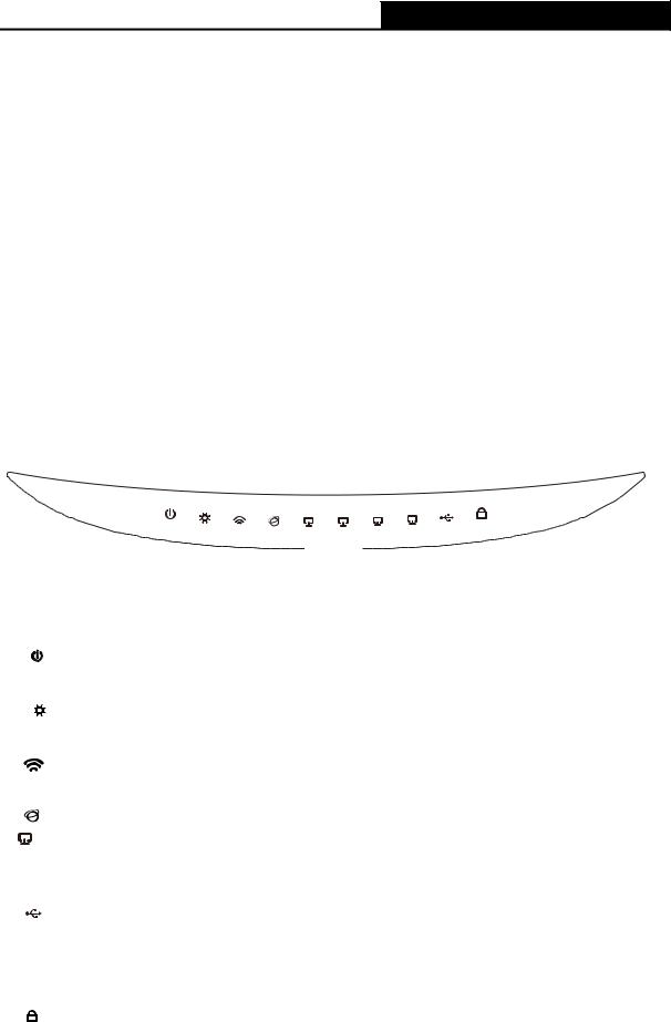
1.4.1The Front Panel
|
|
|
|
|
|
Figure 1-1 Front Panel sketch |
The Router’s LEDs are located on the front panel (View from left to right). |
||||||
|
|
|
|
|
|
|
|
|
Item |
|
Status |
|
Indication |
|
|
(PWR) |
|
On |
|
Power is on. |
|
|
|
Off |
Power is off. |
||
|
|
|
|
|||
|
|
|
|
On |
|
The Router is initializing. |
|
|
(SYS) |
|
|
|
|
|
|
|
Flashing |
The Router is working properly. |
||
|
|
|
|
Off |
The Router has a system error. |
|
|
|
(WLAN) |
|
Flashing |
|
The Wireless function is enabled. |
|
|
|
Off |
The Wireless function is disabled. |
||
|
|
|
|
|||
|
|
WAN |
|
On |
|
A device is linked to the corresponding port but there is no |
|
|
|
|
activity. |
||
|
|
|
|
|
||
|
|
LAN1-4 |
Flashing |
|
An active device is linked to the corresponding port. |
|
|
|
|
|
Off |
|
No device is linked to the corresponding port. |
|
|
|
|
On |
|
The USB 3G/4G modem is connected but no data being |
|
|
USB |
|
|
transferred. |
|
|
|
|
|
|
||
|
|
|
Flashing |
Data is received or sent through the 3G/4G modem. |
||
|
|
|
|
|||
|
|
|
|
Off |
The USB 3G/4G modem is not connected. |
|
|
|
|
|
Slow |
|
A wireless device is connecting to the network by WPS |
|
|
|
|
Flash |
|
function. This process will last in the first 2 minutes. |
|
|
WPS |
|
On |
|
A wireless device has been successfully added to the network |
|
|
|
|
by WPS function. |
||
|
|
|
|
|
|
|
|
|
|
|
Quick |
|
A wireless device failed to be added to the network by WPS |
|
|
|
|
Flash |
|
function. |
Table 1-1 The LEDs description
-3-
TL-MR3420 3G/4G Wireless N Router User Guide
Note:
After a device is successfully added to the network by WPS function, the WPS LED will keep on for about 5 minutes and then turn off.
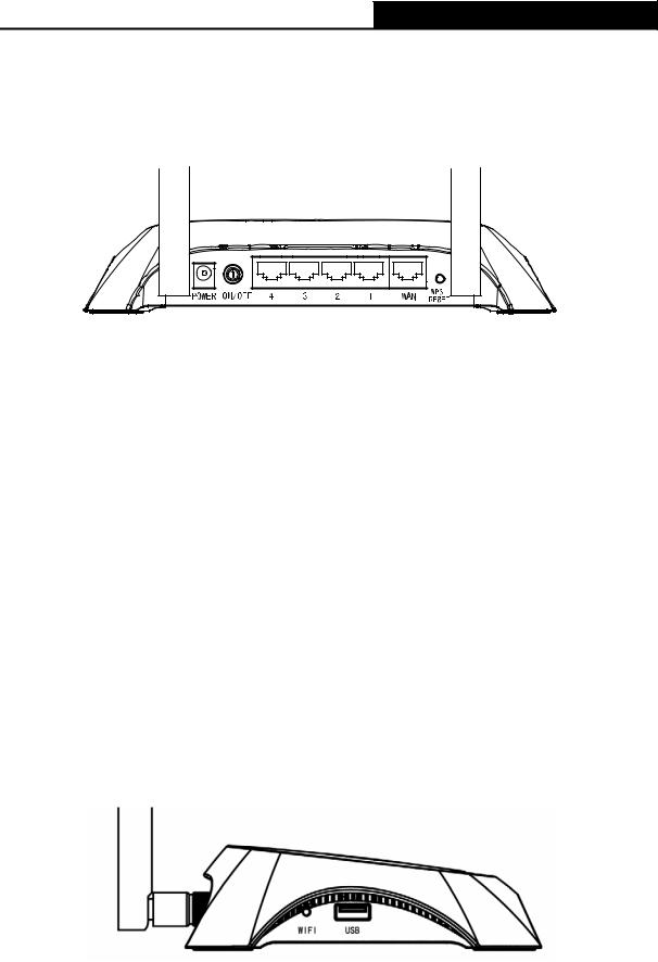
1.4.2The Rear Panel
Figure 1-2 Rear Panel sketch
The following parts are located on the rear panel (View from left to right).
POWER: The Power socket is where you will connect the power adapter. Please use the
power adapter provided with this TL-MR3420 3G/4G Wireless N Router.
ON/OFF: The switch is for you to turn on/off the Router, but only with the Router powered
on.
4,3,2,1 (LAN): These ports (4,3,2,1) connect the Router to the local PC(s)
WAN: This WAN port is where you will connect the DSL/cable Modem, or Ethernet
WPS/RESET:
There are two ways to reset to the Router's factory defaults:
1)Use the Factory Defaults function on “System Tools -> Factory Defaults” page in the Router's Web-based Utility.
2)Use the Factory Default Reset button: With the Router powered on, use a pin to press and hold the WPS/RESET button (about 5 seconds) until the SYS LED becomes quick-flash from slow-flash. And then release the button and wait the Router to reboot to its factory default settings.
Wireless antenna: To receive and transmit the wireless data.
1.4.3The Side Panel
Figure 1-3 Side Panel sketch
The following parts are located on the side plate (View from left to right).
WIFI: This switch is an easy and convenient operation for you to turn on or off the wireless network.
USB: Connect to the USB Modem.
-4-

TL-MR3420 3G/4G Wireless N Router User Guide
Chapter 2.Connecting the Router
2.1 System Requirements
Broadband Internet Access Service (DSL/Cable/Ethernet)
One DSL/Cable Modem that has an RJ45 connector (which is not necessary if the Router is connected directly to the Ethernet.)
PCs with a working Ethernet Adapter and an Ethernet cable with RJ45 connectors TCP/IP protocol on each PC
Web browser, such as Microsoft Internet Explorer 5.0 , Netscape Navigator 6.0 or above
2.2 Installation Environment Requirements
Place the Router in a well ventilated place far from any heater or heating vent Avoid direct irradiation of any strong light (such as sunlight)
Keep at least 2 inches (5 cm) of clear space around the Router Operating Temperature: 0 ~40 (32 ~104 )
Operating Humidity: 10%~90%RH, Non-condensing
2.3 Connecting the Router
Before installing the Router, make sure your PC is connected to the Internet through the broadband service successfully. If there is any problem, please contact your ISP. After that, please install the Router according to the following steps. Don't forget to pull out the power plug and keep your hands dry.
1.Power off your Cable/DSL Modem, and the Router.
2.Locate an optimum location for the Router. The best place is usually at the center of your wireless network. The place must accord with the Installation Environment Requirements.
3.Adjust the direction of the antenna. Normally, upright is a good direction.
4.Connect the PC(s) or Switch/Hub in your LAN to the LAN Ports of the 3G/4G Router with Ethernet cable.
5.The 3G/4G Router supports both 3G/4G and WAN connection; so you can insert 3G/4G USB Modem to the USB port of the Router (as shown in Figure 2-1), or connect the DSL/Cable Modem to the WAN port of the Router (as shown in Figure 2-2). Please visit our website http://www.tp-link.com to get the latest USB modems compatibility, and we recommend you to check whether the modem in your hand has already been tested by us.
6.Connect the power adapter to the power socket on the Router, and the other end into an electrical outlet. The Router will start to work automatically.
7.Power on your Cable/DSL Modem.
-5-

TL-MR3420 3G/4G Wireless N Router User Guide
Figure 2-1 Hardware Installation – 3G/4G connection
Figure 2-2 Hardware Installation – WAN connection
-6-

TL-MR3420 3G/4G Wireless N Router User Guide
Chapter 3.Quick Installation Guide
This chapter will show you how to configure the basic functions of your 3G/4G Wireless N Router using Quick Setup Wizard within minutes.
3.1 TCP/IP Configuration
The default IP address of the 3G/4G Wireless N Router is 192.168.0.1. And the default Subnet Mask is 255.255.255.0. These values can be changed as you desire. In this guide, we use all the default values for description.
Connect the local PC to the LAN ports of the Router. And then you can configure the IP address for your PC in the following two ways.
Configure the IP address manually
1)Set up the TCP/IP Protocol for your PC. If you need instructions as to how to do this, please refer to Appendix B: "Configuring the PC."
2)Configure the network parameters. The IP address is 192.168.0.xxx ("xxx" is any number from 2 to 254), Subnet Mask is 255.255.255.0, and Gateway is 192.168.0.1 (The Router's
default IP address)
Obtain an IP address automatically
1)Set up the TCP/IP Protocol in "Obtain an IP address automatically" mode on your PC. If you need instructions as to how to do this, please refer to Appendix B: "Configuring the PC."
2)Then the built-in DHCP server will assign IP address for the PC.
3.2 Quick Installation Guide
Note:
If you are trying to connect to TL-MR3420 wirelessly, please refer to the label on the bottom of the Router for the Wireless Password.
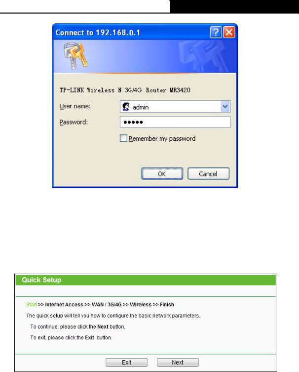
1.To access the configuration utility, open a web-browser and type in the default address http://192.168.0.1 in the address field of the browser.
Figure 3-1 Login the Router
After a moment, a login window will appear, similar to the Figure 3-2. Enter admin for the User Name and Password, both in lower case letters. Then click the OK button or press the Enter key.
-7-
TL-MR3420 3G/4G Wireless N Router User Guide
Figure 3-2 Login Windows
Note:
If the above screen does not pop-up, it means that your Web-browser has been set to a proxy. Go to Tools menu>Internet Options>Connections>LAN Settings, in the screen that appears, cancel the Using Proxy checkbox, and click OK to finish it.
2.After successful login, you can click the Quick Setup to quickly configure your Router. Click Next to proceed to the next screen.
Figure 3-3 Quick Setup
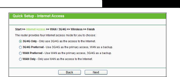
3.Select a desired Internet Access mode and then click Next. The configuration for each mode is similar. As follows we will take 3G/4G Only mode for example.
-8-
TL-MR3420 3G/4G Wireless N Router User Guide
Figure 3-4 Choose Internet Access Mode
3G/4G Only
In this mode, the Router will try 3G/4G access only. WAN access is disabled.
3G/4G Preferred
In this mode, the Router will try 3G/4G access first. If 3G/4G access fails and WAN access is valid, or if no 3G/4G USB modem is inserted, the Router would switch to WAN access. Once the Router succeeds to connect to the 3G/4G network, the Router would stop the WAN connection and switch back to 3G/4G access immediately.
WAN Preferred
In this mode, the Router will try WAN access first. If the WAN access fails and 3G/4G access is valid, the Router would switch to 3G/4G access. Once the Router succeeds to connect to the WAN network, the Router would stop the 3G/4G connection and switch back to WAN access immediately.
WAN Only
In this mode, the Router will try WAN access only. 3G/4G access is disabled.
4.The next screen will appear as shown in Figure 3-5. You need to set the required parameters and then click Next.
-9-

TL-MR3420 3G/4G Wireless N Router User Guide
Figure 3-5
Location - Select the location where you're enjoying the 3G/4G card.
Mobile ISP - Select the ISP (Internet Service Provider) you apply to for 3G/4G service. The Router will show the default Dial Number and APN of that ISP. If your ISP is not listed in the
Mobile ISP, check the box before Set the Dial Number, APN, Username and Password manually and fill the Dial Number and APN blanks below.
Authentication Type - Some ISPs need a specific authentication type. Please confirm it with your ISP or keep it Auto.
Dial Number & APN - Set these two parameters manually after Set the Dial Number, APN, Username and Password manually is checked.
Username/Password - Enter the Username and Password provided by your ISP. These fields are optional but case-sensitive.
5.Configure the Wireless settings on the screen as shown in Figure 3-6, then click Next.
-10-

TL-MR3420 3G/4G Wireless N Router User Guide
Figure 3-6 Quick Setup – Wireless
Wireless Radio - Enable or disable the wireless radio choosing from the pull-down list.
Wireless Network Name - Enter a value of up to 32 characters. The same name of Wireless Network Name (SSID) must be assigned to all wireless devices in your network. Considering your wireless network security, the default Wireless Network Name is set to be TP-LINK_XXXXXX (XXXXXX indicates the last six unique numbers of each Router’s MAC address). This value is case-sensitive. For example, TEST is NOT the same as test.
Region - Select your region from the pull-down list. This field specifies the region where the wireless function of the Router can be used. It may be illegal to use the wireless function of the Router in a region other than one of those specified in this field. If your country or region is not listed, please contact your local government agency for assistance.
Mode - This field determines the wireless mode which the Router works on.
Channel Width - Select any channel width from the pull-down list. The default setting is automatic, which can adjust the channel width for your clients automatically.
Channel - This field determines which operating frequency will be used. The default channel is set to Auto, so the AP will choose the best channel automatically. It is not necessary to change the wireless channel unless you notice interference problems with another nearby access point.
-11-
TL-MR3420 3G/4G Wireless N Router User Guide
Wireless Security - You can select one of the following security options.
Disable Security - The wireless security function can be enabled or disabled. If disabled, the wireless stations will be able to connect the Router without encryption. It is recommended strongly that you choose one of following options to enable security.
WPA-PSK/WPA2-PSK - Select WPA based on pre-shared passphrase.
PSK Password - You can enter ASCII or Hexadecimal characters.
For ASCII, the key can be made up of any numbers 0 to 9 and any letters A to Z, the length should be between 8 and 63 characters.
For Hexadecimal, the key can be made up of any numbers 0 to 9 and letters A to F, the length should be between 8 and 64 characters.
Please also note the key is case sensitive, this means that upper and lower case keys will affect the outcome. It would also be a good idea to write down the key and all related wireless security settings.
No change - If you choose this option, wireless security configuration will not change! These settings are only for basic wireless parameters. For advanced settings, please refer to Section 4.6: “Wireless”.
6.Click Finish to complete the Quick Setup.
Figure 3-7 Quick Setup – Finish
After the rebooting, please check whether you can access the Internet or not in the 4.2 Status page.
-12-
TL-MR3420 3G/4G Wireless N Router User Guide
Chapter 4.Configuring the Router
This chapter will show each Web page's key functions and the configuration way.
4.1 Login
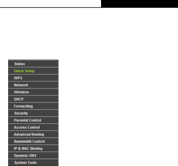
After your successful login, you will see the fifteen main menus on the left of the Web-based utility. On the right, there are the corresponding explanations and instructions.
The detailed explanations for each Web page’s key function are listed below.
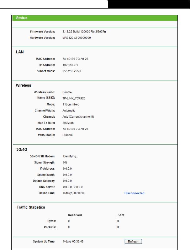
4.2 Status
The Status page displays the current status information about the Router. All information is read-only.
-13-
TL-MR3420 3G/4G Wireless N Router User Guide
Figure 4-1 Status
4.3 Quick Setup
Please refer to Section 3.2: "Quick Installation Guide."
4.4 WPS
This section will guide you to add a new wireless device to an existing network quickly by WPS (Wi-Fi Protected Setup) function.
-14-

TL-MR3420 3G/4G Wireless N Router User Guide
a). Choose menu “WPS”, you will see the next screen (shown in Figure 4-2).
Figure 4-2 WPS
WPS Status - Enable or disable the WPS function here.
Current PIN - The current value of the Router's PIN displayed here. The default PIN of the Router can be found in the label or User Guide.
Restore PIN - Restore the PIN of the Router to its default.
Gen New PIN - Click this button, and then you can get a new random value for the Router's PIN. You can ensure the network security by generating a new PIN.
Disable PIN of this device - WPS external registrar of entering this device's PIN can be disabled or enabled manually. If this device receives multiple failed attempts to authenticate an external Registrar, this function will be disabled automatically.
Add Device - You can add the new device to the existing network manually by clicking this button.
b). To add a new device:
If the wireless adapter supports Wi-Fi Protected Setup (WPS) or QSS (Quick Secure Setup), you can establish a wireless connection between wireless adapter and Router by using either Push Button Configuration (PBC) method or PIN method.
Note:
To build a successful connection by WPS, you should also do the corresponding configuration of the new device for WPS function meanwhile.
For the configuration of the new device, here takes the Wireless adapter of our company for example.
I.By PBC (Push Button Configuration)
If the wireless adapter supports Wi-Fi Protected Setup or Quick Secure Setup and the PBC method, you can add it to the network by PBC with the following two methods.
Method One:
Step 1: Press the WPS/RESET button on the rear panel of the Router.
-15-

TL-MR3420 3G/4G Wireless N Router User Guide
Step 2: Press and hold the WPS or QSS button of the adapter directly for 2 or 3 seconds.
Step 3: Wait for a while until the next screen appears. Click Finish to complete the WPS configuration.
The WPS Configuration Screen of wireless adapter
Method Two:
Step 1: Press the WPS/RESET button on the rear panel of the Router.
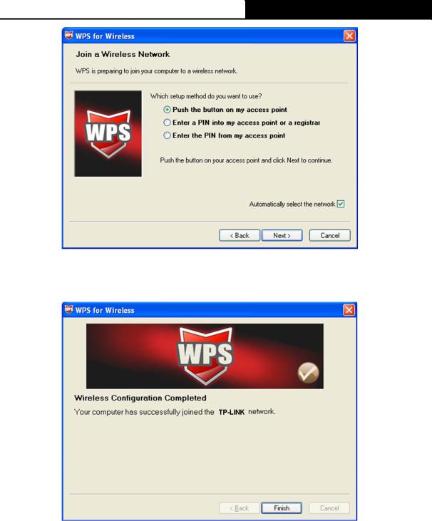
Step 2: For the configuration of the wireless adapter, please choose Push the button on my access point in the configuration utility of the WPS as below, and click Next.
-16-
TL-MR3420 3G/4G Wireless N Router User Guide
The WPS Configuration Screen of wireless adapter
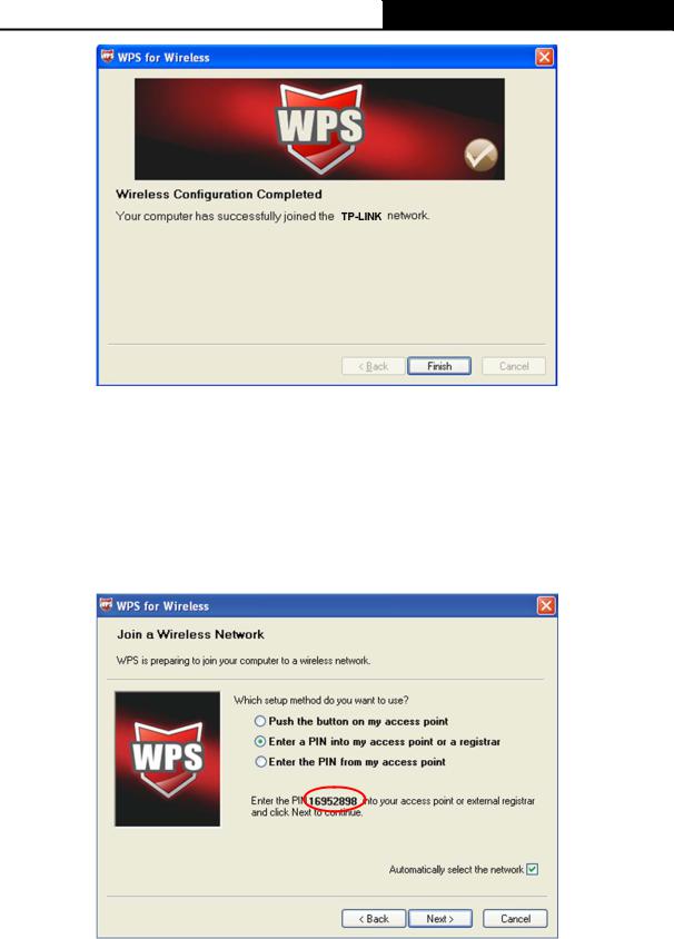
Step 3: Wait for a while until the next screen appears. Click Finish to complete the WPS configuration.
The WPS Configuration Screen of wireless adapter
Method Three:
Step 1: Keep the default WPS Status as Enabled and click the Add device button in Figure 4-2, then the following screen will appear.
-17-
TL-MR3420 3G/4G Wireless N Router User Guide
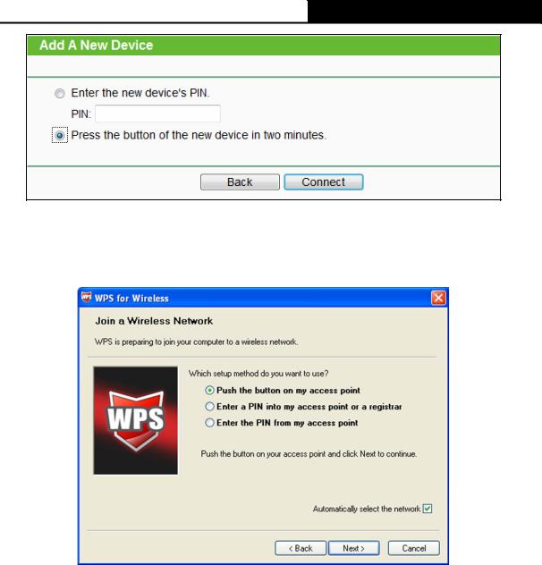
Figure 4-3 Add A New Device
Step 2: Choose Press the button of the new device in two minutes and click Connect. Step 3: For the configuration of the wireless adapter, please choose Push the button on my
access point in the configuration utility of the WPS as below, and click Next.
The WPS Configuration Screen of Wireless adapter
Step 4: Wait for a while until the next screen appears. Click Finish to complete the WPS configuration.
-18-
TL-MR3420 3G/4G Wireless N Router User Guide
The WPS Configuration Screen of Wireless adapter
II. By PIN
If the wireless adapter supports Wi-Fi Protected Setup or Quick Secure Setup and the PIN method, you can add it to the network by PIN with the following two methods.
Method One: Enter the PIN into my Router
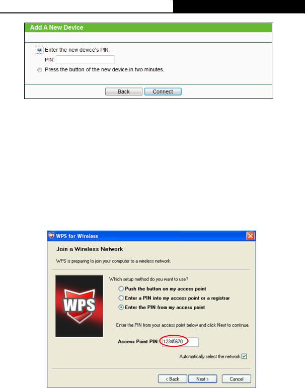
Step 1: Configure the wireless adapter. Please choose Enter a PIN into my access point or a registrar in the configuration utility of the WPS as below, and click Next.
The WPS Configuration Screen of wireless adapter
Note:
In this example, the default PIN code of this adapter is 16952898 as the above figure shown.
Step 2: Configure the Router TL-MR3420. Keep the default WPS Status as Enabled and click the Add device button in Figure 4-2, then the following screen will appear.
-19-
TL-MR3420 3G/4G Wireless N Router User Guide
Step 3: Choose Enter the new device's PIN and enter the PIN code of the wireless adapter in the field behind PIN in the previous figure. Then click Connect.
Note:
The PIN code of the wireless adapter is always displayed on the WPS or QSS configuration screen.
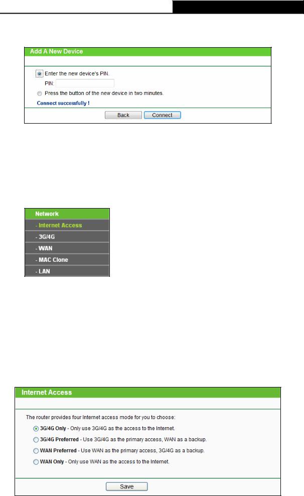
Method Two: Enter the PIN from my Router
Step 1: Get the Current PIN code of the Router in Figure 4-2 (each Router has its unique PIN code. Here takes the PIN code 12345670 of this Router for example).
Step 2: For the configuration of the wireless adapter, please choose Enter a PIN from my access point in the configuration utility of the WPS as below, and enter the PIN code of the Router into the field behind Access Point PIN. Then click Next.
The WPS Configuration Screen of Wireless adapter
Note:
The default PIN code of the Router can be found in its label or the WPS configuration screen as Figure 4-2.
-20-
TL-MR3420 3G/4G Wireless N Router User Guide
c). You will see the following screen when the new device successfully connected to the network.
Note:
1)The status LED on the Router will light green all the time if the device has been successfully added to the network.
2)The WPS function cannot be configured if the Wireless Function of the Router is disabled. Please make sure the Wireless Function is enabled before configuring the WPS.
4.5 Network
Figure 4-4 the Network menu
There are five submenus under the Network menu ( as shown in Figure 4-4): Internet Access, 3G/4G, WAN, MAC Clone and LAN. Click any of them, and you will be able to configure the corresponding function.
4.5.1Internet Access
Choose menu “Network→Internet Access”, you can configure the access mode on the screen below. The Router is designed to work with either WAN port or 3G/4G USB modem, and supports “automatically take over back up with 3G/4G access” as Ethernet WAN failover.
Figure 4-5 Internet Access
-21-
Loading...