


 Loading...
TWG850/DWG855
digital BROADBAND
RESIDENTIAL VOICE GATEWAY

Important Information
CAUTION
Disconnect power before servicing.
This device is intended for indoor operation only. Telephone jacks Line 1 and Line 2 must not be connected to outside wiring.
CAUTION
To ensure reliable operation and to prevent overheating, provide adequate ventilation for this modem and keep it away from heat sources. Do not locate near heat registers or other heat-producing equipment. Provide for free air flow around the Residential Voice Gateway and its power supply.
NORTH AMERICAN CABLE INSTALLER:
This reminder is provided to call your attention to Article 820-40 of the National Electrical Code (Section 54 of the Canadian Electrical Code, Part 1) which provides guidelines for proper grounding and, in particular, specifies that the cable ground shall be connected to the grounding system of the building as close to the point of cable entry as practical.
Euro-PacketCable, Euro-DOCSIS, and DOCSIS compliant (TWG850)
This product was designed according to Euro-PacketCable Specification, Euro-DOCSIS Specifications and Data over Cable Service Interface Specifications.
CableHome, PacketCable, and DOCSIS compliant (DWG855)
This product was designed according to CableHome Specifications, PacketCable Voice over IP Cable Telephony Specifications and Data over Cable Service Interface Specifications.
It will operate on any DOCSIS-compliant Hybrid Fiber Coax (HFC) cable system and offers DOCSIS and PacketCable Baseline Privacy to promote secure internet transactions and PC-secure telephone service.
Operating Information
Operating Temperature: 0˚ - 40˚ C (32˚ - 104˚ F) Storage Temperature:-30˚ to 65˚ C
If you purchased this product at a retail outlet, please read the following: ii
Product Information
Keep your sales receipt to obtain warranty parts and service and for proof of purchase. Attach it here and record the serial and model numbers in case you need them. The numbers are located on the back of the product.
Model No. ____________________________Serial No ________________________________
Purchase Date: ________________________Dealer/Address/Phone: _________________________
Illustrations contained in this document are for representation only. |
iii |
Chapter 1: Connections and Setup |
|
Introduction ............................................................................................................................ |
1 |
Residential Voice Gateway Features ................................................................................... |
1 |
What’s on the CD-ROM ..................................................................................................... |
1 |
Computer Requirements.................................................................................................... |
3 |
Wall Mounting ................................................................................................................... |
4 |
Residential Voice Gateway TWG850 Overview........................................................................... |
6 |
Front Panel........................................................................................................................ |
6 |
Rear Panel ......................................................................................................................... |
7 |
Residential Voice Gateway DWG855 Overview .......................................................................... |
8 |
Front Panel........................................................................................................................ |
8 |
Rear Panel ....................................................................................................................... |
10 |
Installing the Battery ....................................................................................................... |
10 |
Relationship among the Devices ............................................................................................ |
12 |
What the Modem Does .................................................................................................... |
12 |
What the Modem Needs to Do Its Job............................................................................... |
12 |
Contact Your Local Cable Company ................................................................................. |
13 |
Connecting the Residential Voice Gateway to a Single Computer............................................ |
15 |
Attaching the Cable TV Wire to the Residential Voice Gateway ......................................... |
15 |
Important Connection Information .................................................................................. |
16 |
USB Connection to One Computer ................................................................................... |
16 |
USB Connection............................................................................................................... |
18 |
Using Windows 2000 for USB Connection ........................................................................ |
18 |
Using Windows Me for USB Connection............................................................................ |
22 |
Using Windows XP for USB Connection ............................................................................ |
23 |
iv |
|
Ethernet Connection to One Computer ............................................................................ |
25 |
Connecting More Than Two Computers to the Residential Voice Gateway ........................ |
27 |
Telephone or Fax Connection.......................................................................................... |
29 |
Activating the Residential Voice Gateway ............................................................................... |
31 |
Chapter 2: Web Configuration |
|
Accessing the Internet ........................................................................................................... |
33 |
Outline of Web Manager .................................................................................................. |
34 |
Status.................................................................................................................................... |
35 |
Software.......................................................................................................................... |
35 |
Connection...................................................................................................................... |
35 |
Security........................................................................................................................... |
36 |
Diagnostics ..................................................................................................................... |
36 |
Wireless................................................................................................................................. |
37 |
Basic ............................................................................................................................... |
37 |
Security........................................................................................................................... |
39 |
Access Control ................................................................................................................ |
42 |
Advanced ........................................................................................................................ |
43 |
Bridging .......................................................................................................................... |
44 |
Chapter 3: Additional Information |
|
Frequently Asked Questions .................................................................................................. |
45 |
General Troubleshooting ....................................................................................................... |
47 |
FCC Declaration of Conformity and Industry Canada Information........................................... |
49 |
Service Information................................................................................................................ |
50 |
Glossary ................................................................................................................................ |
51 |
Illustrations contained in this document are for representation only. |
v |

Chapter 1: Connections and Setup
Introduction
Residential Voice Gateway Features
zSupport Multiple Provisioning Mode
zStandard RJ-45 connector for 10/100BaseT Ethernet with auto-negotiation and MDIS functions
zUSB Connector for USB interface
zTwo RJ-11 Foreign Exchange Station (FXS) ports for IP telephony
zSupport simultaneous voice and data communications
zTwo simultaneous voice conversations in the different FXS ports with different CODEC: PCM A-law, PCM-law, G.723.1, G.729, G.729a, G.729e, G.728, G.726, BV16 and BV32
zEcho Cancellation
zVoice Active Detection (VAD)
zDTMF detection and generation
zComfort Noise Generation (CNG)
zSupport V.90 fax and modem services
zTransparent bridging for IP traffic
zRSA and 56 bit DES data encryption security
zSNMP network management support
zRemote operating firmware downloading
zSupport Web pages and private DHCP server for status monitoring
zClear LED display
zPlug and Play
What’s on the CD-ROM
Insert the Residential Voice Gateway CD-ROM into your CD-ROM drive to view troubleshooting tips, the internal diagnostics, and other valuable information.
Note: You might need to use the CD-ROM to install the USB driver if you are connecting via the USB port.
Illustrations contained in this document are for representation only. |
1 |
Chapter 1: Connections and Setup
CD-ROM Contents:
zElectronic copy of this user’s guide in additional languages (PDF format)
zAdobe Acrobat Reader — application you can load to read PDF format, if you don’t have it loaded already
zUSB drivers — required if connecting by USB
zLinks to Thomson and RCA web sites
DOCSIS and PacketCable are trademarks of Cable Television Laboratories, Inc.
2

Chapter 1: Connections and Setup
Computer Requirements
For the best possible performance from your Residential Voice Gateway, your personal computer must meet the following minimum system requirements (note that the minimum requirements may vary by cable companies):
|
IBM PC COMPATIBLE |
MACINTOSH** |
|
|
PowerPC or higher |
CPU |
Pentium preferred |
|
|
|
24MB (32MB preferred) |
System RAM |
16MB (32MB preferred) |
|
|
|
Mac OS** 7.6.1 or higher |
Operating System |
Windows* NT/2000/Me/XP, |
|
|
Linux |
|
|
|
50MB |
Available Disk Space |
125MB |
|
|
|
N/A |
Sound Card |
Required for audio on CD-ROM |
|
|
|
VGA or better (SVGA built-in |
Video |
VGA or better (SVGA preferred) |
|
|
|
preferred) |
|
|
Required |
CD-ROM Drive |
Required |
|
|
|
10BaseT or 100BaseT |
Ethernet |
10BaseT or 100BaseT |
|
|
An Ethernet card makes it possible for your computer to pass data to |
|
|
and from the internet. You must have an Ethernet card and software |
|
|
drivers installed in your computer. You will also need a standard |
|
|
Ethernet cable to connect the Ethernet card to your Residential Voice |
|
|
Gateway. |
|
|
|
|
USB Port |
USB (Windows 2000/ME/XP only) |
|
|
The Universal Serial Bus is a high speed bus that enables your |
|
|
computer to communicate simultaneously with a variety of |
|
|
peripherals. However, if you have other peripherals that send and |
|
|
receive a lot of information, such as speakers, printers or scanners, we |
|
|
recommend using an Ethernet card to support this modem. |
|
|
|
|
Illustrations contained in this document are for representation only. |
3 |
Chapter 1: Connections and Setup
Software |
• |
A TCP/IP network protocol for each machine |
|
• |
Microsoft Internet Explorer 4.0 or later or Netscape Navigator 4.0 or |
|
|
later. (5.0 and 4.7 or later, respectively, are strongly |
|
|
recommended.) |
*Windows is a trademark of Microsoft Corporation.
**Macintosh and the Mac OS are trademarks of Apple Computer, Inc.
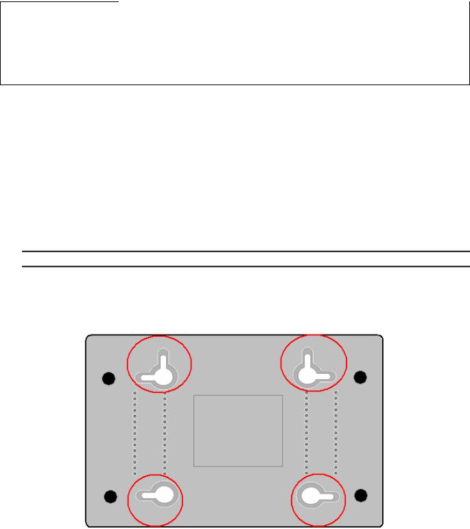
Wall Mounting
The number of the screw: 2 pcs
Direction for wall mounting: LED panel upward.
Dimension for the screw: TBD
There are 4 slots on the underside of the EMTA that can be used for wall mounting.
Note: When wall mounting the unit, ensure that it is within reach of the power outlet.
You will need 2 suitable screws which screw diameter would be 4.4 mm to wall mount the Cable Modem or the Battery Pack. Two different wall mount directions could be chosen for the Battery Pack.
To do this:
1.Ensure that the wall you use is smooth, flat, dry and sturdy and use the 4 screw holes which are 101.6 mm apart from each other.
2.Fix the screws into wall, leaving their heads 3 mm (0.12 inch) clear of the wall surface.
4
Chapter 1: Connections and Setup
3.Remove any connections to the unit and locate it over the screw heads. When in line, gently push the unit on to the wall and move it downwards to secure.
Illustrations contained in this document are for representation only. |
5 |
Chapter 1: Connections and Setup
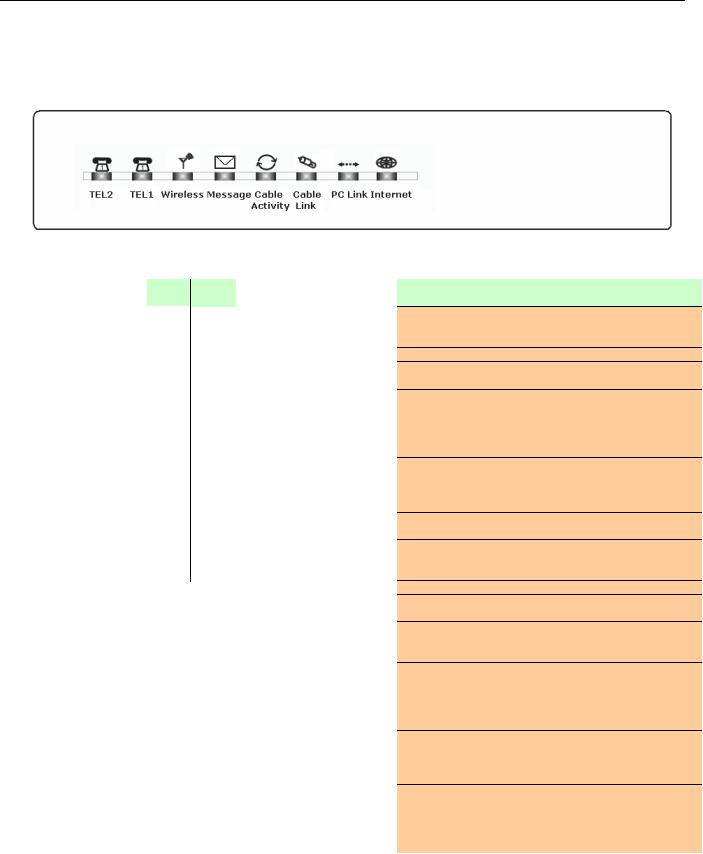
Residential Voice Gateway TWG850 Overview
Front Panel
The following illustration shows the front panel of the TWG850 machine:
The LEDs on the front panel are described in the table below (from left to right):
|
Tel 2 |
Tel 1 |
WirelessMessage |
Cable |
Cable |
PC |
Internet |
Description |
||
|
Activity |
Link |
Link |
|||||||
|
ON |
ON |
|
|
ON |
ON |
|
|
|
Power on 0.25 sec |
|
ON |
|
ON |
ON |
ON |
|||||
|
ON |
0.25 |
|
0.25 second |
|
|||||
|
|
|
||||||||
Boot-up |
sec |
|
|
|
|
|
|
|||
|
|
|
|
|
|
|
|
|
||
Operation |
ON |
FLASH |
X |
|
FLASH |
FLASH |
X |
X |
X |
From power ON to system initialization complete |
|
ON |
ON |
X |
|
ON |
ON |
X |
X |
X |
Following system initialization complete to (before) DS |
|
1 sec |
|
1 second |
scanning |
||||||
|
|
|
|
|
|
|
||||
|
X |
X |
X |
|
OFF |
OFF |
OFF |
OFF |
FLASH |
Tuning |
|
|
|
|
|
|
|
|
|
|
(Searching downstream signal) |
|
|
|
|
|
|
|
|
|
|
Ranging - Awaiting Response |
|
X |
X |
X |
|
OFF |
OFF |
OFF |
FLASH |
FLASH |
(DS carrier acquire, ranging in process but RNG-RSP has |
|
|
|
|
|
|
|
|
|
|
not been detected) |
|
X |
X |
X |
|
OFF |
OFF |
OFF |
FLASH |
FLASH |
Any RNG-RSP detected |
Start-up |
|
|
|
|
|
|
|
|
|
(Normalizing power level and timing offset) |
|
|
|
|
|
|
|
|
|
Connecting |
|
Operation |
X |
X |
X |
|
OFF |
OFF |
FLASH |
FLASH |
FLASH |
|
|
|
|
|
|
|
|
|
|
|
(Ranging complete, DHCP in progress) |
|
X |
X |
X |
|
OFF |
FLASH |
FLASH |
FLASH |
FLASH |
Configuring (DHCP complete, configuration file download |
|
|
|
|
|
|
|
|
|
|
in process) |
|
X |
X |
X |
|
FLASH |
FLASH |
FLASH |
FLASH |
FLASH |
Registering and Baseline Privacy Initializing |
|
|
(configuration file download complete, initialize BPI if BPI is |
||||||||
|
|
|
|
|
|
|
|
|
|
ON, registration in process) |
|
X |
X |
|
|
Enter Normal |
Operation |
Mode |
|
Registration complete |
|
|
X |
X |
X |
|
X |
X |
X |
X |
FLASH |
NO Cable Link |
|
|
ON |
CM is registered |
|||||||
|
|
|
|
|
|
|
|
|
||
|
X |
X |
X |
|
X |
X |
X |
OFF |
X |
NO Ethernet/USB carrier present |
|
|
FLASH |
Ethernet/USB TX/RX traffic |
|||||||
|
|
|
|
|
|
|
|
ON |
|
Ethernet/USB carrier present, no traffic |
|
|
|
|
|
|
|
OFF |
|
|
NO Cable Link |
|
X |
X |
X |
|
X |
X |
X |
X |
||
|
|
FLASH |
Cable BSS/OSS has set the CM into de-activated state |
|||||||
Normal |
|
|
|
|
|
|
ON |
|
|
CM is registered |
|
|
|
|
|
OFF |
|
|
|
Internet ON-OFF switch off/No RF DS/US network traffic |
|
Operation |
X |
X |
X |
|
X |
X |
X |
X |
||
|
FLASH |
RF DS/US network traffic |
||||||||
|
|
|
|
|
|
|
|
|
||
|
|
|
|
|
OFF |
|
|
|
|
No message is delivered by the MSO |
|
|
|
|
|
|
|
|
|
||
|
X |
X |
X |
|
FLASH |
X |
X |
X |
X |
Email is available fro the user on the server |
|
|
|
(Implementation of the message waiting LED will be via |
|||||||
|
|
|
|
|
|
|
|
|
|
|
|
|
|
|
|
|
|
|
|
|
Proprietary MIB) |
|
|
|
OFF |
|
|
|
|
|
|
Wireless initiate fail or disable |
|
X |
X |
|
X |
X |
X |
X |
X |
||
|
ON |
|
Wireless initiate success or enable |
|||||||
|
|
|
FLASH |
|
|
|
|
|
|
TX/RX Wireless Traffic |
No service |
X |
X |
X |
|
X |
X |
Wink |
X |
X |
NACO =OFF |
Operation |
X |
X |
X |
|
3 seconds ON followed by a flash OFF |
BPI unauthorized (when BPI is ON) |
||||
6
Chapter 1: Connections and Setup
|
Tel 1 |
WirelessMessage |
Cable |
Cable |
PC |
Internet |
Description |
Tel 2 |
|||||||
|
|
|
Activity |
Link |
Link |
|
|
MTA |
OFF |
FLASH |
|
|
|
MTA DHCP |
FLASH |
OFF |
|
|
|
MTA SNMP/TFTP |
|
initialization |
|
|
|
|||
|
FLASH |
FLASH |
|
<CM Normal Operation> |
RSIP |
|
|
ON |
ON |
|
Both Lines On-Hook |
||
MTA |
ON |
FLASH |
|
|
|
Tel1 Off-hook, Tel2 On-hook |
Operation |
FLASH |
ON |
|
|
|
Tel1 On-hook, Tel2 Off-hook |
|
FLASH |
FLASH |
|
|
|
Both Lines Off-Hook |
SW |
X |
X |
X |
FLASH |
FLASH FLASH FLASH |
FLASH A software download and while updating the FLASH |
Download |
X |
X |
X |
|
From Right to Left |
memory |
Operation |
|
|
||||
|
|
|
|
|
|
|
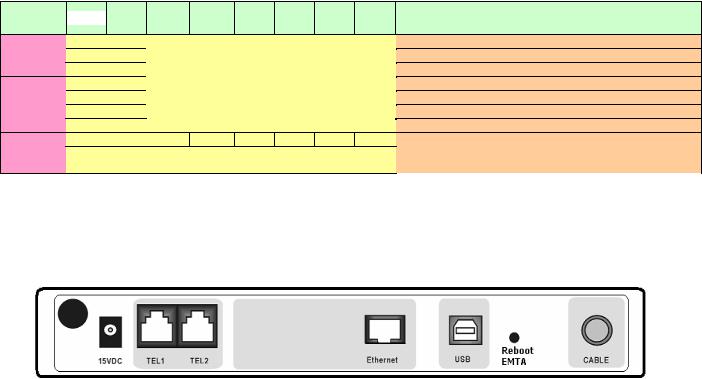
Rear Panel
15VDC: |
15V DC-IN Power connector |
TEL1 & TEL2 |
Telephony RJ-11 connector |
ETHERNET: |
Ethernet 10/100BaseT RJ-45 connector |
USB: |
USB Connector |
REBOOT EMTA: |
Reboot this Residential Voice Gateway |
CABLE: |
F-Connector |
Illustrations contained in this document are for representation only. |
7 |

Chapter 1: Connections and Setup
Residential Voice Gateway DWG855 Overview
Front Panel
The following illustration shows the front panel of the DWG855 machine:
The LEDs on the front panel are described in the table below (from left to right):
|
Power |
|
Internet |
|
|
Ethernet |
|
|
Tel 1 |
Tel 2 |
Battery |
Wireless |
USB |
Description |
|
|||||
|
DS |
US |
Online |
1 |
|
2 |
|
3 |
|
4 |
|
|
||||||||
|
|
|
|
|
|
|
|
|
|
|
|
|
||||||||
|
ON |
ON |
ON |
ON |
ON |
|
ON |
|
ON |
|
ON |
|
ON |
ON |
X |
ON |
ON |
Power on 0.25 sec |
|
|
|
ON |
0.25 second |
|
|
|
|
|
|||||||||||||
|
|
|
|
|
|
|
|
|
|
|
|
|
|
|
|
|||||
|
|
|
|
|
|
|
|
|
|
|
|
|
|
|
|
|
|
From power ON to |
||
Boot-up |
ON |
FLASH |
FLASH |
FLASH |
X |
|
X |
|
X |
|
X |
|
X |
X |
X |
X |
X |
system initialization |
||
Operation |
|
|
|
|
|
|
|
|
|
|
|
|
|
|
|
|
|
complete |
||
|
ON |
ON |
ON |
ON |
X |
|
X |
|
X |
|
X |
|
X |
X |
X |
X |
X |
Following system |
|
|
|
|
|
|
|
|
|
|
initialization complete |
|
|||||||||||
|
1 second |
|||||||||||||||||||
|
|
|
|
|
|
|
|
|
|
|
|
|
|
|
to (before) DS scanning |
|
||||
|
|
|
|
|
|
|
|
|
|
|
|
|
|
|
|
|
|
|
||
|
ON |
FLASH |
OFF |
OFF |
X |
|
X |
|
X |
|
X |
|
X |
X |
X |
X |
X |
During DS scanning and |
||
|
|
|
|
|
acquiring SYNC |
|||||||||||||||
|
|
|
|
|
|
|
|
|
|
|
|
|
|
|
|
|
|
|||
|
|
|
|
|
|
|
|
|
|
|
|
|
|
|
|
|
|
From SYNC completed, |
||
|
ON |
ON |
FLASH |
OFF |
X |
|
X |
|
X |
|
X |
|
X |
X |
X |
X |
X |
receiving UCD to |
||
DOCSIS |
|
|
|
|
|
|
|
|
|
|
|
|
|
|
|
|
|
ranging completed |
||
|
|
|
|
|
|
|
|
|
|
|
|
|
|
|
|
|
During DHCP, |
|
||
Start-up |
|
|
|
|
|
|
|
|
|
|
|
|
|
|
|
|
|
|
||
|
|
|
|
|
|
|
|
|
|
|
|
|
|
|
|
|
configuration file |
|
||
Operation |
|
|
|
|
|
|
|
|
|
|
|
|
|
|
|
|
|
|
||
ON |
ON |
ON |
FLASH |
X |
|
X |
|
X |
|
X |
|
X |
X |
X |
X |
X |
download, registration, |
|
||
|
|
|
|
|
|
|||||||||||||||
|
|
|
|
|
|
|
|
|
|
|
|
|
|
|
|
|
|
and Baseline Privacy |
|
|
|
|
|
|
|
|
|
|
|
|
|
|
|
|
|
|
|
|
initialization |
|
|
|
ON |
ON |
ON |
ON |
X |
X |
X |
X |
X |
X |
X |
X |
X |
Operational (NACO=ON) |
||||||
|
ON |
FLASH |
FLASH |
OFF |
X |
X |
X |
X |
X |
X |
X |
X |
X |
Operational(NACO=OFF) |
||||||
MTA |
ON |
ON |
ON |
ON |
X |
|
X |
|
X |
|
X |
|
FLASH |
OFF |
OFF |
X |
X |
MTA DHCP |
|
|
ON |
ON |
ON |
ON |
X |
X |
X |
X |
OFF |
FLASH |
OFF |
X |
X |
MTA SNMP/TFTP |
|||||||
initialization |
||||||||||||||||||||
ON |
ON |
ON |
ON |
X |
X |
X |
X |
FLASH |
FLASH |
OFF |
X |
X |
RSIP |
|||||||
|
||||||||||||||||||||
|
|
|
|
|
OFF |
|
OFF |
|
OFF |
|
OFF |
|
|
|
|
|
|
No Ethernet Link |
|
|
|
|
|
|
|
|
|
|
|
|
|
|
|
|
|
||||||
|
ON |
X |
X |
X |
ON |
|
ON |
|
ON |
|
ON |
|
X |
X |
X |
X |
X |
Ethernet Link |
|
|
|
FLASH |
|
FLASH |
|
FLASH |
|
FLASH |
|
TX/RX Ethernet Traffic |
|
||||||||||
|
|
|
|
|
|
|
|
|
|
|
|
|
|
|
||||||
CPE |
|
|
|
|
ON |
|
ON |
|
ON |
|
ON |
|
|
|
|
|
|
Ethernet Collision |
|
|
Operation |
|
|
|
|
|
|
|
|
|
|
|
|
|
|
|
|
OFF |
No USB Link |
||
|
ON |
X |
X |
X |
X |
|
X |
|
X |
|
X |
|
X |
X |
X |
X |
ON |
USB Link |
||
|
|
|
|
|
FLASH |
TX/RX USB Traffic |
||||||||||||||
|
|
|
|
|
|
|
|
|
|
|
|
|
|
|
|
|
||||
|
|
|
|
|
|
|
|
|
|
|
|
|
|
|
|
|
ON |
USB driver is not ready |
||
8
Chapter 1: Connections and Setup
|
Power |
|
|
Internet |
|
Ethernet |
|
Tel1 |
|
Tel2 |
|
Battery |
Wireless |
|
USB |
Description |
|
|||
|
|
DS |
US |
Online |
1 |
2 |
|
3 |
4 |
|
|
|
|
|||||||
|
|
|
|
|
|
|
|
|
|
|
|
|
|
|||||||
|
|
|
|
|
|
|
|
|
|
|
|
|
|
|
|
OFF |
|
|
No Wireless Link |
|
|
|
|
|
|
|
|
|
|
|
|
|
|
|
|
|
|
|
Wireless Link |
|
|
CPE |
|
|
|
|
|
|
|
|
|
|
|
|
|
|
|
ON |
|
|
|
|
ON |
|
X |
X |
X |
X |
X |
|
X |
X |
X |
|
X |
|
X |
|
X |
TX/RX Wireless Traffic |
|
||
Operation |
|
|
|
|
FLASH |
|
|
|||||||||||||
|
|
|
|
|
|
|
|
|
|
|
|
|
|
|
|
|
Wireless is not installed |
|
||
|
|
|
|
|
|
|
|
|
|
|
|
|
|
|
|
ON |
|
|
|
|
|
|
|
|
|
|
|
|
|
|
|
|
|
|
|
|
|
|
or disable |
|
|
|
|
|
|
|
|
|
|
|
|
|
|
|
|
|
|
|
|
|
|
|
|
ON |
|
|
|
|
|
|
|
|
ON |
ON |
|
|
|
|
Both Lines On-Hook |
||||
|
ON |
|
|
|
|
|
|
|
|
|
FLASH |
|
ON |
|
|
|
|
|
Tel1 Off-hook, Tel2 |
|
AC Good |
|
|
|
|
|
|
|
|
|
|
|
ON |
|
|
|
On-hook |
||||
|
|
|
|
|
|
|
|
|
|
|
|
|
|
|
|
|
||||
Battery Good |
|
|
|
|
|
|
|
|
|
|
|
|
|
|
|
|
|
Tel1 On-hook, Tel2 |
|
|
ON |
|
|
|
|
|
|
|
|
|
ON |
|
FLASH |
|
|
|
|
|
|
||
|
|
|
|
|
|
|
|
|
|
|
|
|
|
|
|
|
||||
|
|
|
|
|
|
|
|
|
|
|
|
|
|
|
|
|
|
|
Off-hook |
|
|
ON |
|
|
|
|
|
|
|
|
FLASH |
FLASH |
|
|
|
|
Both Lines Off-Hook |
||||
|
ON |
|
|
|
|
|
|
|
|
ON |
ON |
|
|
|
|
Both Lines On-Hook |
||||
|
ON |
|
|
|
|
|
|
|
|
|
FLASH |
|
ON |
|
|
|
|
|
Tel1 Off-hook, Tel2 |
|
AC Good |
|
|
|
|
|
|
|
|
|
|
|
|
<CM Normal |
On-hook |
|
|||||
|
|
|
<CM Normal Operation> |
|
|
|
|
|
|
FLASH |
|
|||||||||
|
|
|
|
|
|
|
|
|
|
|
||||||||||
Battery Low |
ON |
|
|
|
|
|
|
|
|
|
ON |
|
FLASH |
|
|
Operation> |
Tel1 On-hook, Tel2 |
|||
|
|
|
|
|
|
|
|
|
|
|
|
|
|
|
|
Off-hook |
||||
|
|
|
|
|
|
|
|
|
|
|
|
|
|
|
|
|
|
|
||
|
ON |
|
|
|
|
|
|
|
|
FLASH |
FLASH |
|
|
|
|
Both Lines Off-Hook |
||||
|
ON |
|
|
|
|
|
|
|
|
|
ON |
|
ON |
|
|
|
|
|
Both Lines On-Hook |
|
|
|
|
|
|
|
|
|
|
|
|
|
|
|
|
|
|
||||
AC Good |
ON |
|
|
|
|
|
|
|
|
|
FLASH |
|
ON |
|
|
|
|
|
Tel1 Off-hook, Tel2 |
|
|
|
|
|
|
|
|
|
|
|
|
OFF |
|
|
|
On-hook |
|||||
|
|
|
|
|
|
|
|
|
|
|
|
|
|
|
|
|
||||
Battery Bad |
ON |
|
|
|
|
|
|
|
|
|
ON |
|
FLASH |
|
|
|
|
Tel1 On-hook, Tel2 |
||
|
|
|
|
|
|
|
|
|
|
|
|
|
|
|
||||||
|
|
|
|
|
|
|
|
|
|
|
|
|
|
|
|
Off-hook |
||||
|
|
|
|
|
|
|
|
|
|
|
|
|
|
|
|
|
|
|
||
|
ON |
|
|
|
|
|
|
|
|
|
FLASH |
|
FLASH |
|
|
|
|
|
Both Lines Off-Hook |
|
|
|
|
|
|
|
|
|
|
|
|
ON |
|
|
|
|
|
|
Both Lines On-Hook |
||
|
|
|
|
|
|
|
|
|
|
|
FLASH |
|
|
|
|
|
|
|
Tel1 Off-hook, Tel2 |
|
AC Fail |
|
|
|
|
|
|
|
|
|
|
|
|
|
OFF |
|
|
|
On-hook |
||
|
|
|
|
|
|
|
|
|
|
|
|
|
|
|
|
|
||||
Battery Good |
|
|
|
|
|
|
|
|
|
|
ON |
|
|
|
|
|
|
Tel1 On-hook, Tel2 |
|
|
|
|
|
|
|
|
|
|
|
|
|
|
|
|
|
|
|
|
|||
|
|
|
|
|
|
|
|
|
|
|
|
|
|
|
|
|
|
Off-hook |
|
|
|
|
|
|
|
|
|
|
|
|
|
|
|
|
|
|
|
|
|
|
|
|
FLASH |
|
|
|
|
OFF |
|
|
|
|
FLASH |
|
|
|
OFF |
|
Both Lines Off-Hook |
|||
|
|
|
|
|
|
|
|
|
ON |
|
|
|
|
Both Lines On-Hook |
||||||
|
|
|
|
|
|
|
|
|
|
|
|
|
|
|
|
|
||||
|
|
|
|
|
|
|
|
|
|
|
FLASH |
|
|
|
|
|
|
|
Tel1 Off-hook, Tel2 |
|
AC Fail |
|
|
|
|
|
|
|
|
|
|
|
OFF |
|
FLASH |
|
|
|
On-hook |
|
|
|
|
|
|
|
|
|
|
|
|
|
|
|
|
|
|
|
||||
Battery Low |
|
|
|
|
|
|
|
|
|
|
ON |
|
|
|
|
|
Tel1 On-hook, Tel2 |
|||
|
|
|
|
|
|
|
|
|
|
|
|
|
|
|
|
|
||||
|
|
|
|
|
|
|
|
|
|
|
|
|
|
|
|
|
|
Off-hook |
||
|
|
|
|
|
|
|
|
|
|
|
|
|
|
|
|
|
|
|
||
|
|
|
|
|
|
|
|
|
|
|
FLASH |
|
|
|
|
|
|
Both Lines Off-Hook |
||
|
|
|
|
|
|
|
|
|
|
|
|
|
|
|
|
|
|
|
Both Lines On-Hook |
|
|
|
|
|
|
|
|
|
|
|
|
|
|
|
|
|
|
|
|
|
|
|
|
|
|
|
|
|
|
|
|
|
|
|
|
|
|
< All LEDs may |
Tel1 Off-hook, Tel2 |
|||
AC Fail |
< All LEDs may be unlit due to lack of battery power> |
|
|
|
OFF |
be unlit due to |
On-hook |
|||||||||||||
Battery Bad |
|
|
|
lack of battery |
Tel1 On-hook, Tel2 |
|||||||||||||||
|
|
|
|
|
|
|
|
|
|
|
|
|
|
|
||||||
|
|
|
|
|
|
|
|
|
|
|
|
|
|
|
|
power> |
Off-hook |
|||
|
|
|
|
|
|
|
|
|
|
|
|
|
|
|
|
|
|
|
Both Lines Off-Hook |
|
SW |
|
|
|
|
|
|
|
|
|
|
|
|
|
|
|
|
|
|
A software download |
|
Download |
ON |
|
FLASH |
FLASH |
ON |
X |
X |
|
X |
X |
X |
|
X |
|
X |
X |
|
X |
and while updating the |
|
Operation |
|
|
|
|
|
|
|
|
|
|
|
|
|
|
|
|
|
|
FLASH memory |
|
|
|
|
|
|
|
|
|
|
|
|
|
|
|
|
|
|
|
|
|
|
Illustrations contained in this document are for representation only. |
9 |

Chapter 1: Connections and Setup
Rear Panel
TEL1 & TEL2 |
Telephony RJ-11 connector |
ETHERNET 1-4: |
Ethernet 10/100BaseT RJ-45 connector |
USB: |
USB Connector |
REBOOT EMTA: |
Reboot this Residential Voice Gateway |
CABLE: |
F-Connector |
Rating 100-240V: |
Power connector |
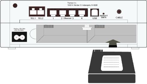
Installing the Battery
This section provides you information of installing batteries into the modem. Follow the steps below:
1.Unplug the power cord of the power adapter from the modem if you have plugged it.
2.Remove the cover of the rear panel. There are two spare drives for you to install the battery.
10
Chapter 1: Connections and Setup
3. Insert the battery into the rear battery drive with the direction that the following picture shows.
4.Put back the cover of the rear panel.
5.Now, the cable modem is on with the power of the battery. It is not necessary for you to use power adapter again.
Illustrations contained in this document are for representation only. |
11 |
Chapter 1: Connections and Setup
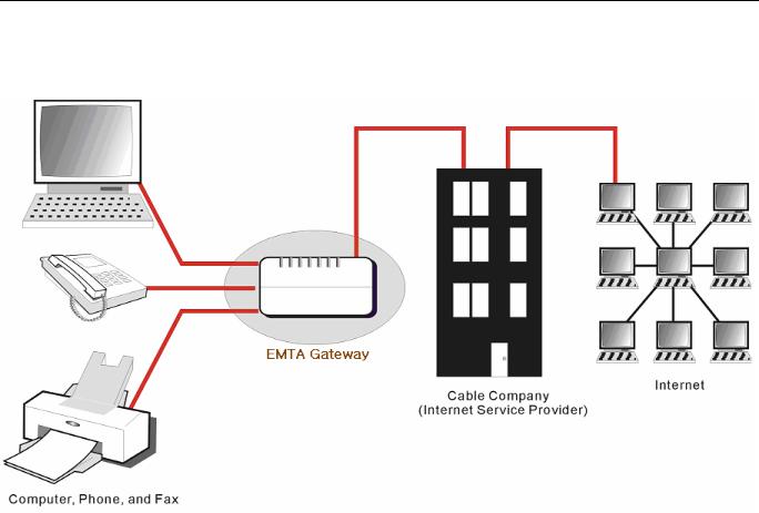
Relationship among the Devices
This illustration shows a cable company that offers DOCSISand PacketCable-compliant voice/data services.
What the Modem Does
The Residential Voice Gateway provides high-speed Internet access as well as cost-effective, toll-quality telephone voice and fax/modem services over residential, commercial, and education subscribers on public and private networks via an existing CATV infrastructure. It can inter-operate with the PacketCable compliant headend equipment and provide the IP-based voice communications. The IP traffic can transfer between the Residential Voice Gateway and DOCSIS compliant headend equipment. The data security secures upstream and downstream communications.
What the Modem Needs to Do Its Job
The Right Cable Company: Make sure your local cable company provides data services that use cable TV industry-standard Euro-DOCSIS or DOCSIS-compliant and Euro-PacketCable or PacketCable-compliant technology.
12
Loading...