


TSC 800
TRANSFER SWITCH CONTROLLER
INSTALLATION, OPERATING &
SERVICE MANUAL
Software Version 2.1
PM049 REV 9 06/04/24
9087A – 198th Street, Langley, BC Canada V1M 3B1 Telephone (604) 888-0110 Telefax (604) 888-3381 E-Mail: info@thomsontechnology.com www.thomsontechnology.com
9087A – 198th Street, Langley, BC Canada V1M 3B1 Telephone (604) 888-0110 Telefax (604) 888-3381 E-Mail: info@thomsontechnology.com www.thomsontechnology.com

TSC 800 TRANSFER SWITCH CONTROLLER
|
|
TABLE OF CONTENTS |
|
1. |
INTRODUCTION |
1 |
|
|
1.1. |
PRODUCT REVISION HISTORY |
1 |
|
1.2. |
GENERAL DESCRIPTION |
2 |
2. |
INSTALLATION |
5 |
|
|
2.1. |
GENERAL INFORMATION |
5 |
|
2.2. |
NOTES TO INSTALLER |
5 |
|
2.3. |
AC VOLTAGE SENSING INPUT |
6 |
|
2.4. |
AC CONTROL POWER INPUT |
6 |
|
2.5. |
OUTPUTS |
7 |
|
2.6. |
SYSTEM PHASING-HIGH LEG DELTA SYSTEMS |
7 |
|
2.7. |
EXTERNAL PANEL CONTROL WIRING |
10 |
|
2.8. |
REMOTE START CONTACT FIELD WIRING |
10 |
|
2.9. |
COMMMUNICATION CABLE |
11 |
|
2.10. |
DIELECTRIC TESTING |
12 |
3. |
DESCRIPTION |
12 |
|
|
3.1. |
LEXAN FACEPLATE |
12 |
|
3.2. |
PRINTED CIRCUIT BOARD |
14 |
|
3.2.1. POWER SUPPLY INPUT VOLTAGE SELECTION |
14 |
|
|
3.2.2. |
TERMINAL BLOCKS |
15 |
|
3.2.3. |
DIAGNOSTIC LEDs |
15 |
|
3.2.4. |
COMMUNICATION PORT |
16 |
|
3.2.5. |
CONTRAST ADJUSTMENT |
16 |
4. |
REMOTE COMMUNICATION |
16 |
|
5. TSC 800 DISPLAY MENUS |
19 |
||
|
5.1. |
SYSTEM TIME MENU |
19 |
|
5.2. |
ATS MODE MENU |
20 |
|
5.3. |
TSC 800 PROGRAM MENU |
23 |
|
5.4. |
SYSTEM OPERATION MENU |
23 |
|
5.5. |
TIMER COUNTDOWN MENUS |
25 |
PM 049 REV 9 06/04/24 |
Thomson Technology |

TSC 800 TRANSFER SWITCH CONTROLLER
|
5.6. |
UTILITY SUPPLY MENU |
26 |
|
5.7. |
GENERATOR SUPPLY MENU |
27 |
|
5.8. |
STATS MENU |
28 |
6. |
OPERATING INSTRUCTIONS |
29 |
|
|
6.1. AUTOMATIC SEQUENCE OF OPERATION |
29 |
|
|
6.1.1. |
NORMAL SEQUENCE OF OPERATION (OPEN TRANSITION TRANSFER) |
29 |
|
6.1.2. |
NORMAL SEQUENCE OF OPERATION (CLOSED TRANSITION TRANSFER) |
30 |
|
6.1.3. |
TEST MODE SEQUENCE OF OPERATION |
31 |
|
6.1.4. |
ABNORMAL SEQUENCE OF OPERATION |
33 |
|
6.2. |
LCD DISPLAY OPERATION |
33 |
|
6.4.1 |
OPERATOR INITIATED UTILITY POWER FAIL SIMULATION (LOAD TEST) |
35 |
|
6.4.2 |
AUTOMATIC PLANT EXERCISE TEST |
36 |
|
6.4.3 |
FOUR FUNCTION REMOTE TEST (FTS4 OPTION) |
36 |
|
6.5 |
TRANSFER FAIL FAULT RESET |
38 |
|
6.6 |
LAMP TEST |
38 |
|
6.7 |
TIMER BYPASS |
38 |
|
6.8 |
MANUAL UTILITY RE-TRANSFER |
39 |
|
6.9 |
SERVICE ENTRANCE ATS MODE |
39 |
|
6.10 PHASE BALANCE PROTECTION ALARM |
39 |
|
7. |
PROGRAMMING INSTRUCTIONS |
41 |
|
|
7.1. |
PASSWORDS |
41 |
|
7.1.1. |
READ ONLY MODE |
41 |
|
7.1.2. |
READ / WRITE MODE |
41 |
|
7.1.3. |
MASTER READ / WRITE MODE |
41 |
|
7.2. |
EXERCISE TIMER |
42 |
|
7.2.1. |
SYSTEM TIME ROLLOVER |
43 |
|
7.2.2. |
AUTO TEST START DAY/WEEK NUMBER |
43 |
|
7.2.3. |
AUTO TEST START HOUR |
43 |
|
7.2.4. |
AUTO TEST START MINUTE |
43 |
|
7.2.5. |
AUTO TEST STOP DAY/WEEK NUMBER |
43 |
|
7.2.6. |
AUTO TEST STOP HOUR |
44 |
|
7.2.7. |
AUTO TEST STOP MINUTE |
44 |
|
7.2.8. |
AUTO TEST MODE |
44 |
|
7.3. |
SYSTEM CONFIGURATION |
44 |
|
7.3.1. |
FIRMWARE VERSION |
44 |
|
7.3.2. |
ATS MODE MENU PASSWORD (PW) |
45 |
|
7.3.3. |
UTILITY FAIL CALLOUT |
45 |
|
7.3.4. |
LOAD ON GENERATOR CALLOUT |
45 |
|
7.3.5. |
TRANSFER FAIL CALLOUT |
46 |
|
7.3.6. |
AUTO TEST CALLOUT |
46 |
|
7.3.7. |
MAN TEST CALLOUT |
46 |
|
7.3.8. |
SWITCH NOT IN AUTO CALLOUT |
46 |
PM 049 REV 9 06/04/24 |
Thomson Technology |

TSC 800 TRANSFER SWITCH CONTROLLER
7.3.9. |
|
NODE ADDRESS |
47 |
7.3.10. |
SYSTEM VOLTAGE |
47 |
|
7.3.11. |
VOLTAGE SENSING RATIO |
47 |
|
7.3.12. |
SYSTEM FREQUENCY |
47 |
|
7.3.13. |
SYSTEM PHASES |
47 |
|
7.3.14. |
LOAD SENSING PHASES |
48 |
|
7.3.15. |
PHASE BALANCE |
48 |
|
7.3.16. |
PHASE BALANCE DELAY |
48 |
|
7.3.17. |
PHASE BALANCE RETRANSFER |
49 |
|
7.4. |
VOLTAGE SENSING |
49 |
|
7.4.1. UTILITY UNDER VOLTAGE SENSOR PICKUP |
49 |
||
7.4.2. UTILITY UNDER VOLTAGE SENSOR DROPOUT |
50 |
||
7.4.3. UTILITY UNDER VOLTAGE SENSOR TIME DELAY (DROPOUT) |
50 |
||
7.4.4. UTILITY OVER VOLTAGE SENSOR PICKUP |
50 |
||
7.4.5. UTILITY OVER VOLTAGE SENSOR DROPOUT |
50 |
||
7.4.6. UTILITY OVER VOLTAGE SENSOR TIME DELAY (PICKUP) |
51 |
||
7.4.7. UTILITY UNDER FREQUENCY SENSOR |
51 |
||
7.4.8. UTILITY UNDER FREQUENCY SENSOR TIME DELAY (DROPOUT) |
51 |
||
7.4.9. UTILITY OVER FREQUENCY SENSOR |
51 |
||
7.4.10. UTILITY OVER FREQUENCY SENSOR TIME DELAY (PICKUP) |
51 |
||
7.4.11. GENERATOR UNDER VOLTAGE SENSOR PICKUP |
51 |
||
7.4.12. GENERATOR UNDER VOLTAGE SENSOR DROPOUT |
52 |
||
7.4.13. GENERATOR UNDER VOLTAGE SENSOR TIME DELAY (DROPOUT) |
52 |
||
7.4.14. GENERATOR OVER VOLTAGE SENSOR PICKUP |
52 |
||
7.4.15. GENERATOR OVER VOLTAGE SENSOR DROPOUT |
52 |
||
7.4.16. GENERATOR OVER VOLTAGE SENSOR TIME DELAY (PICKUP) |
52 |
||
7.4.17. GENERATOR UNDER FREQUENCY SENSOR |
53 |
||
7.4.18. GENERATOR UNDER FREQUENCY SENSOR TIME DELAY (DROPOUT) |
53 |
||
7.4.19. GENERATOR OVER FREQUENCY SENSOR |
53 |
||
7.4.20. GENERATOR OVER FREQUENCY SENSOR TIME DELAY (PICKUP) |
53 |
||
7.5. |
GENERATOR CONTROL LOGIC |
53 |
|
7.5.1. COMMIT TO TRANSFER LOGIC |
53 |
||
7.5.2. |
|
GENERATOR START DELAY |
54 |
7.5.3. |
|
GENERATOR WARMUP DELAY |
54 |
7.5.4. |
|
GENERATOR COOLDOWN DELAY |
54 |
7.5.5. |
|
PRE-TRANSFER DELAY (LDC) |
54 |
7.5.6. |
|
POST-TRANSFER DELAY (LDC) |
54 |
7.5.7. |
|
TRANSFER LOGIC |
55 |
7.5.8. LOAD ON UTILITY PROGRAMMABLE OUTPUT |
55 |
||
7.5.9. LOAD ON GENERATOR PROGRAMMABLE OUTPUT |
57 |
||
7.5.10. MAXIMUM FIND NEUTRAL DELAY |
57 |
||
7.5.11. NEUTRAL DELAY TIMER (NDT) |
58 |
||
7.5.12. |
NEUTRAL DELAY BYPASS |
58 |
|
7.5.13. |
MAXIMUM TRANSFER TIME |
58 |
|
7.5.14. |
TRANSFER FAIL |
58 |
|
7.5.15. MANUAL UTILITY TRANSFER RETURN |
59 |
||
7.5.16. |
UTILITY RETURN DELAY |
60 |
|
7.5.17. |
MAX SYNC TIME |
60 |
|
7.5.18. MAX POWER SWITCHING DEVICE OPEN TIME |
60 |
||
7.5.19. |
PROGRAMMABLE OUTPUT |
60 |
|
7.6. |
VOLTAGE SENSING CALIBRATION |
62 |
|
7.6.1. |
|
GENERAL |
62 |
7.6.2. |
|
UTILITY VOLTAGE CALIBRATION |
63 |
7.6.3. |
|
GENERATOR VOLTAGE CALIBRATION |
66 |
7.6.4. |
|
LOAD VOLTAGE CALIBRATION |
68 |
PM 049 REV 9 06/04/24 |
Thomson Technology |

TSC 800 TRANSFER SWITCH CONTROLLER
8. |
TSC 800 PROGRAMMING DATA SHEETS |
71 |
|
9. |
TSC 800 TYPICAL CONNECTION DIAGRAM |
76 |
|
10. |
TSC 800 SPECIFICATIONS |
77 |
|
11. |
TROUBLESHOOTING |
78 |
|
12. |
REPLACEMENT PARTS |
81 |
|
13. |
PRODUCT RETURN POLICY |
83 |
|
14. |
NOTES |
84 |
|
PM 049 REV 9 06/04/24 |
Thomson Technology |

TSC 800 TRANSFER SWITCH CONTROLLER
1.INTRODUCTION
1.1.PRODUCT REVISION HISTORY
The following information provides an historical summary of changes made to this product since the original release.
Software Version
2.1 |
06/03/27 |
Enhanced Phase Balance Features |
|
|
|
2.0 |
04/12/14 |
New Features (Refer to Section 1.2) |
|
|
|
1.7 |
02/04/01 |
Revised Transfer Fail Features and functionality |
1.6 |
98/12/15 |
Added Remote Communication |
|
|
|
1.5 |
N/A |
Unreleased version |
|
|
|
1.4 |
98/06/15 |
Updated Transfer Fail operation |
|
|
|
1.3 |
98/01/19 |
Updated default under/over frequency setpoints, transfer fail |
|
|
programmability, minor logic revisions |
|
|
|
1.2 |
97/10/10 |
Changed Transfer Switch fail timer to 30 seconds |
|
|
|
1.1 |
97/01/30 |
Upgraded Frequency setting range |
|
|
|
1.0 |
96/06/30 |
Original version |
Operating & Service Manual Version |
||
|
|
|
Rev 9 06/04/24 |
Minor manual revisions for Version 2.1 TSC 800 Software |
|
|
|
Production Release |
Rev 8 06/03/27 |
Enhanced phase balance features |
|
|
|
|
Rev 7 04/12/16 |
New Features (Refer to Section 1.2) |
|
|
|
|
Rev 6 02/04/15 |
Changes for Version 1.7 TSC 800 Software |
|
|
|
|
Rev 5 00/07/31 |
Added Four Position Test Switch Information |
|
|
|
|
Rev 4 00/03/01 |
General revisions |
|
|
|
|
Rev 3 99/02/12 |
Added Multi-tap information. |
|
|
|
|
Rev 2 98/12/01 |
Added Remote Communication features per version 1.6 TSC 800 |
|
|
|
Software |
|
|
|
Rev 1 98/01/21 |
General Revisions for upgraded TSC 800 software |
|
|
|
|
Rev 0 97/06/04 |
Original release |
|
|
|
|
Contact Thomson Technology, to obtain applicable instruction manuals. Soft copy of most current version is available at www.thomsontechnology.com.
PM 049 REV 9 06/04/24 |
1 |
Thomson Technology |

TSC 800 TRANSFER SWITCH CONTROLLER
1.2.GENERAL DESCRIPTION
The TSC 800 controller utilizes microprocessor-based design technology, which provides high accuracy for all voltage sensing and timing functions. The TSC 800 is factory configured to control all the operational functions and display features of the automatic transfer switch. All features of the TSC 800 are fully programmable from the front panel LCD display and are security password protected. The LCD display screen prompts are in plain English, providing a user-friendly operator interface with many display options available. The microprocessor design provides many standard features, which were previously only available as add-on optional features.
A summary of new and enhanced features provided in SOFTWARE VERSION 2.0 Release is as follows:
On Board Data Logging
o Total Number of Transfers
o Total Number of Transfers due to source failure o Number of Hours Controller is energized
o Number of Hours Load is on Utility
o Number of Hours Load is on GeneratorTimer Bypass Function
o Faceplate Key Press Can Bypass Various Displayed Control Timer o Timer is Automatically Reset on Next Sequence
o Operator Can Initiate Immediate Actions When DesiredPhase Balance Sensing
o Ensures Load is Fed from Balanced Source o Programmable Voltage Tolerance Settings
o Phase Balance on Both Utility & Generator SourcesAutomatic or Manual Retransfer to Utility
o User Programmable Retransfer Modes in Software
o Manual Retransfer Requires Operator Key Press to Initiate Retransfer to Utility once Available
o Manual Re-transfer is Automatically Bypassed on Generator FailureAuto Test Timer
oTransfer Switch Allows User to Initiate an “Auto Test” Mode and after a Preprogrammed Time Delay, ATS Retransfers Back to Utility
o 15 – 240 Min. User Programmable Timer in Software
PM 049 REV 9 06/04/24 |
2 |
Thomson Technology |

TSC 800 TRANSFER SWITCH CONTROLLER
o Auto Test Timer is Automatically Bypassed on GeneratorExtended Timer
Ranges |
|
|
|
|
o |
Warmup Timer |
0 |
– |
3000 seconds (was 30 minutes) |
o |
Cooldown Timer |
0.0 |
– 50.0 minutes (was 30 minutes) |
|
o |
Neutral Delay Timer |
0 |
– |
120 seconds (was 60 seconds) |
o |
Utility Return Timer |
0 |
– |
50.0 minutes (was 30 minutes) |
o |
Pre/Post Transfer Delay |
0 – 300 seconds (was 120 seconds) |
||
7, 14, 21, 28 Day Programmable Exercise Timer
oSingle Event Programmed Either Weekly, Every Second Week, Every Third Week or Once a Month
o Allows Exercising On or Off Load (Programmable) o All Settings Stored in Non-Volatile Memory
Programmable Commit to Transfer Logic
o Transfer Logic can be Programmed to either Logic Scenario:Commit to Transfer to Generator Source only after Transfer to Generator Signal has been Initiated (Existing Logic)
Or
b)Commit to Transfer to Generator Source only after Engine Start Delay Timer Has Expired (New Logic). Can be used to prevent multiple Engine Starts. Auto resetting if the generator fails to start in 5 minutes.
Neutral Delay Bypass
o Neutral Delay Logic can be Programmed to either Logic Scenario:
a) When Disabled includes the programmed Neutral Delay Time once neutral positioning has been determined (Existing Logic).
Or
b) When Enabled only use as much of the programmed Neutral Delay Time as required in the neutral position until the load bus voltage drops below 20% of the nominal system voltage then completes the transfer to the alternate source (New logic). Can be used to reduce the total transfer time while still providing BEMF protection to the connected loads and/or power source. Also reduces retransfer times on loss of alternate source by reducing or cancelling the neutral delay time in a safe manner.
Transfer Fail Logic & Alarming
oMore Descriptive Alarm Messaging: Utility Fail to Transfer, Generator Fail to Transfer, Utility Power Switching Failed, Generator Power Switching Device Failed
PM 049 REV 9 06/04/24 |
3 |
Thomson Technology |

TSC 800 TRANSFER SWITCH CONTROLLER
o Reduced time to detection of a Power Switching Device Failure
oClosed Transition ATS Models with Alarming in Software (Fail to Sync/Close, Fail to Trip)
Standard Over Voltage & Frequency Sensing o Previously Available only as on Option
o3 Phase Utility & Generator Over Voltage and Over Frequency Sensing/Protection is Now Provided as Standard
o Programmable Setpoints and Transient Time DelaysStandard RS422 Remote Communications Port
o Previously Available only as an Option
oCommunication Port Can be used with Thomson Technology CIM (for ModbusTM or THS Software) or Direct Connect previously only as an option
o Utility source available (within voltage, frequency, & phase balance limits)
o Generator source available (within voltage, frequency & phase balance limits) o ATS Not in Auto
o 2nd Engine start output
o Utility & Generator sources available
Security Access for Key Pad Accessible ATS Mode Operation
oUser can Select Security Password prompts to permit access to Manually Initiated Test Modes via the Key Pads
o Master Level Password Required to Change Access
Auto Scrolling & Test Mode DisplayLCD Display will now Auto Scroll all Status Display Screens when no key presses have been initiated for more than 2 minutes
oActivated Test Modes will now be displayed in Status Display Screens without need to re-enter the Test Mode Menu to view current selection
oSleep Mode - If No Key Presses, LCD/VFD Display Blanks for Longer Life when no key presses have been initiated for more than 5 minutes
TM |
Trademarks belong to their respective parties. |
|
For detailed information on all new and enhanced features refer to specific sections within this manual.
PM 049 REV 9 06/04/24 |
4 |
Thomson Technology |
TSC 800 TRANSFER SWITCH CONTROLLER
2.INSTALLATION
CAUTION
contents subject to damage by
STATIC ELECTRICITY
This equipment contains static-sensitive parts. Please observe the following anti-static precautions at all times when handling this equipment. Failure to observe these precautions may cause equipment failure and/or damage.
∙Discharge body static charge before handling the equipment (maintain exposed body contact with a properly grounded surface while handling the equipment, a grounding wrist strap can/should also be utilized).
∙Do not touch any components on the printed circuit board with your hands or any other conductive equipment.
Do not place the equipment on or near materials such as Styrofoam, plastic and vinyl. Place the equipment on properly grounded surfaces and only use an anti-static bag for transporting the equipment.
2.1.GENERAL INFORMATION
NOTE:
Installations should be done in accordance with all applicable electrical regulation codes as required.
The following installation guidelines are provided for general information only pertaining to typical site installations. For specific site installation information, consult Thomson Technology as required. NOTE: Factory installations of THOMSON TECHNOLOGY supplied transfer switches that have been tested and proven may deviate from these recommendations.
2.2.NOTES TO INSTALLER
If the transfer switch has programmable/multi-tap system voltage capability (refer to electrical schematic), confirm the transfer switch has been configured for the system voltage.
PM 049 REV 9 06/04/24 |
5 |
Thomson Technology |
TSC 800 TRANSFER SWITCH CONTROLLER
WARNING
Failure to confirm and match transfer switch voltage with the system voltage could cause serious equipment damage.
If the transfer switch requires reconfiguring, the TSC 800 controller will also require reprogramming.
CAUTION!!!
Qualified personnel must complete all installation and/or service work performed only. Failure to do so may cause personal injury or death.
2.3.AC VOLTAGE SENSING INPUT
The TSC 800 can accept direct AC voltage sensing inputs on the generator and utility supplies from 120-600VAC (nominal). NOTE: Direct input voltage sensing can only be used when the system utilizes a 3 phase, 4 wire distribution system which has the neutral conductor solidly grounded. For 3 phase, 3 wire systems (i.e. no neutral) or high voltage systems, potential transformers must be used (this is also the case where only 1 of the 2 supplies are 3 ph 3 w). Refer to FIGURES 1-4 for voltage sensing connections.
2.4.AC CONTROL POWER INPUT
The TSC 800 is factory supplied for either 115VAC or 230VAC (nominal) control power input voltage. Independent AC control power is required from both utility and generator supplies. AC control power is utilized for internal TSC 800 control circuits and external control device loads. The TSC 800 requires approximately 12VA AC power for internal control circuits. The maximum external load is limited by output contact ratings (i.e. 10A resistive, 120/250VAC). Total AC control power requirements for each supply must be determined by adding both internal and external load requirements.
PM 049 REV 9 06/04/24 |
6 |
Thomson Technology |

TSC 800 TRANSFER SWITCH CONTROLLER
2.5.OUTPUTS
The TSC 800 provides the following types of output circuits:
Engine Start Contact Programmable Output Contact Transfer to Utility Output Transfer to Generator output Pre/post-transfer to utility Pre/post-transfer to generator Load on utility
Load on generator
Isolated Form C contact (10A, 250VAC Resistive) Isolated Form C contact (10A, 250VAC Resistive) 250VAC1, 10A (Resistive) powered output contact 250VAC1, 10A (Resistive) powered output contact 250VAC1, 3A (Resistive) powered output contact 250VAC1, 3A (Resistive) powered output contact 250VAC1, 3A (Resistive) powered output contact 250VAC1, 3A (Resistive) powered output contact
1 NOTE: Output voltage is dependent upon AC control power input voltage (i.e. 120VAC or 230VAC nominal).
Interposing relays are required between the TSC 800 outputs and the end device if loads exceed the output current rating.
Transient suppression devices are required for all inductive devices sharing wiring or if physically located near the transfer switch controller.
For AC operated relays or solenoids, use a suitably rated metal oxide varistor (MOV) or capacitor/resistor suppressor. MOV selection should typically be equal to or slightly greater than 1.3 times the nominal RMS voltage being applied to the inductive device.
NOTE: Selecting an MOV of too low a value can/will result in a sustained short circuit and ultimately result in equipment failure.
2.6.SYSTEM PHASING-HIGH LEG DELTA SYSTEMS
When the transfer switch is connected to 3 phase 4 wire delta systems and no multi tap power supply transformers supplied with the ATS, the “High” leg, must be connected to Phase B of the Utility and/or Generator supply inputs to the ATS (Phase B, colored Orange per “NEC 384-3(e)” identified as the leg with highest potential with reference to ground). This will ensure the ATS control power that is internally connected between phase A and neutral is maintained at 120VAC. Refer to figure below for further details.
WARNING
Failure to match correct system phasing will result in serious damage to the TSC 800 controller.
PM 049 REV 9 06/04/24 |
7 |
Thomson Technology |
TSC 800 TRANSFER SWITCH CONTROLLER
Automatic Transfer
Switch (Utility Supply)
PH A |
PH B |
PH C |
Neural |
(UA) |
(UB) |
(UC) |
(N) |
B
(Orange)
(High Leg)
240V |
208V |
240V |
A |
120V |
120V |
C |
(Red) |
|
|
(Yellow) |
N
(W hite)
PM 049 REV 9 06/04/24 |
8 |
Thomson Technology |

TSC 800 TRANSFER SWITCH CONTROLLER
TSC 800 |
A |
B |
C |
N |
TSC 800 |
L1 |
L2 |
N |
|
|
|
|
GRD |
|
|
|
GRD |
TB1-1 |
|
|
|
|
TB1-1 |
|
|
|
TB1-2 |
|
|
|
|
TB1-2 |
|
|
|
TB1-3 |
|
|
|
|
TB1-3 |
|
|
|
|
|
|
|
|
NO CONNECTION |
|
|
|
TB3-1 |
1 |
|
|
|
TB1-10 |
|
|
|
|
|
|
|
|
|
|
||
TB3-5 |
120 |
|
|
|
TB3-1 |
|
|
|
|
|
|
|
|
|
|
||
TB2-18 |
GRD |
|
|
|
TB3-5 |
|
|
|
|
GRD |
|
|
|
TB2-18 |
|
|
|
|
|
|
|
|
|
|
|
|
|
|
|
|
|
GRD |
|
|
|
VOLTAGE INPUTS |
|
600VAC L-L, 347VAC L-N |
|
480VAC L-L, 277VAC L-N |
|
380VAC L-L, 220VAC L-N |
VOLTAGE INPUTS |
208VAC L-L, 120VAC L-N |
240VAC L-L, 120VAC L-N |
|
1PT REQUIRED FOR TRANSFER SWITCH MECHANISM POWER (MUST BE SIZED TO SUIT POWER REQUIREMENTS).
FIG:1 |
FIG:2 |
3Ø, 4W 208/380/480/600VAC DIRECT SENSING |
1Ø, 3W 120/240VAC DIRECT SENSING |
NOTE: UTILITY VOLTAGE SENSING AND |
NOTE: UTILITY VOLTAGE SENSING SHOWN ONLY. |
CONTROL POWER SHOWN ONLY. |
TSC 800 |
|
A B C N |
TSC 800 |
A B C |
|
|
|
||
|
|
|
GRD |
|
TB1-1 |
|
|
TB1-1 |
|
|
|
|
|
|
TB1-2 |
120 |
|
|
120 |
|
|
TB1-2 |
||
|
|
|
|
|
TB1-3 |
120 |
|
TB1-3 |
120 GRD |
|
|
|||
|
120 |
|
TB3-1 |
1 |
TB3-1 |
|
|
|
|
|
GRD |
|
|
|
|
|
|
120 |
|
|
120 |
|
TB3-5 |
|
TB3-5 |
|
|
||
|
|
|
||
|
|
|
|
|
TB2-18 |
GRD |
1 |
TB2-18 |
GRD |
|
|
|
||
|
GRD |
|
|
GRD |
|
|
|
|
|
SECONDARY PT VOLTAGE |
SECONDARY PT VOLTAGE |
|||
208VAC L-L, 120VAC L-N |
120VAC L-L [NO NEUTRAL] |
|||
120VAC L-L, 69VAC L-N |
NOTE: ØB IS GROUNDED |
|||
|
|
|
||
1 PT REQUIRED FOR TRANSFER SWITCH MECHANISM POWER
(MUST BE SIZED TO SUIT POWER REQUIREMENTS). 1 PT REQUIRED FOR TRANSFER SWITCH MECHANISM POWER (MUST BE SIZED TO SUIT POWER REQUIREMENTS).
FIG:3 |
FIG:4 |
3Ø, 4W WYE PT's |
3Ø, 3W DELTA PT's |
NOTE: UTILITY VOLTAGE SENSING SHOWN ONLY. |
NOTE: UTILITY VOLTAGE SENSING SHOWN ONLY. |
|
|
G:\ENGINEER\PRODUCTS\TSC800\852619.VSD |
REVISED 97/06/27 09:12 AM |
PM 049 REV 9 06/04/24 |
9 |
Thomson Technology |

TSC 800 TRANSFER SWITCH CONTROLLER
2.7.EXTERNAL PANEL CONTROL WIRING
As a minimum, all control wiring shall conform to the local regulatory authority on electrical installations. Specific wire sizes listed below are for typical circuits of distances up to 500ft (150m)1, are as follows:
Utility or Generator Voltage Sensing |
#14 AWG (2.5mm2) |
Transfer output signals |
#14 AWG (2.5mm2) |
Remote Start Contact for Engine Controls |
#14 AWG (2.5mm2) |
NOTE: For long control wire runs or noisy electrical environments the control wires should be twisted & shielded with a suitable drain wire. The shielded cable drain wire must be grounded at one end only. The drain wire grounding location may vary as micro-processor controllers generally exist at both ends (engine generator set & transfer switch) and one may be more susceptible depending on the level of induced noise. The most susceptible controller will requiring the shield ground point as close as possible to the controller. Wire runs from 500ft to 1000ft should be twisted and shielded and increased to #12 AWG where total loop resistance is greater than 5 ohms.
1 |
For distances exceeding 1000ft. (300m) consult Thomson Technology |
|
2.8.REMOTE START CONTACT FIELD WIRING
Field wiring of a remote start contact from a transfer switch to a control panel should conform to the following guidelines to avoid possible controller malfunction and/or damage.
2.8.1.Remote start contact wires (2 #14 AWG (2.5mm2)) should be run in a separate conduit (ferromagnetic type) and in all cases separated from any AC wiring.
2.8.2.Avoid wiring near AC power cables to prevent pick-up of induced voltages.
2.8.3.An interposing relay may be required if field-wiring distance is excessively long (i.e. greater than 1000 feet (300m)) and/or if a remote contact has a resistance of greater than 5.0 ohms. In extremely noisy environments, the wire run lengths indicated may not provide reliable operation and can only be corrected by the use of an interposing relay. The interposing relay is generally installed at the engine controls and utilizes DC power. It is strongly suggested that the ground return wire of the interposing relay be used for the interface to the TSC 800 remote start contact, this will ensure integrity of the DC power supply to the engine generator set controls in the event of a shorted or grounded wire remote start interface wire.
PM 049 REV 9 06/04/24 |
10 |
Thomson Technology |

TSC 800 TRANSFER SWITCH CONTROLLER
2.8.4.The remote start contact provided is voltage free (i.e. dry contact). Exposing the remote start contact to voltage or current levels in excess of its rating will damage the transfer controller.
2.9.COMMMUNICATION CABLE
Communication cable wiring from the controller’s communication port must be suitably routed to protect it from sources of electrical interference. Guidelines for protection against possible electrical interference are as follows:
∙Use high quality, 8 conductor shielded cable only with drain wire grounded at the controller end only.
∙Route the communication cable at least 3 M (10’) away from sources of electrical noise such as variable speed motor drives, high voltage power conductors, UPS systems, transformers, rectifiers etc.
∙Use separate, dedicated conduit runs for all communication cables. Do not tightly bundle communication cables together in the conduit. Conduit should be ferromagnetic type near sources of possible electrical interference. The entire length of conduit should be grounded to building earth ground.
∙When communication cables must cross over low or high voltage AC power conductors, the communication cables must cross at right angles and not in parallel with the conductors.
For additional information on protection against electrical interference, contact THOMSON TECHNOLOGY factory.
PM 049 REV 9 06/04/24 |
11 |
Thomson Technology |
TSC 800 TRANSFER SWITCH CONTROLLER
2.10. DIELECTRIC TESTING
Do not perform any high voltage dielectric testing on the transfer switch with the TSC 800 controller connected into the circuit, as serious damage will occur to the controller. All AC control fuses or control circuit isolation plugs connected to the TSC 800 must be removed/disconnected if high voltage dielectric testing is performed on the transfer switch.
3.DESCRIPTION
The TSC 800 controller consists of two parts; a Lexan faceplate, which is mounted externally on the transfer switch door, and a printed circuit board (PCB), which is mounted inside the transfer switch door.
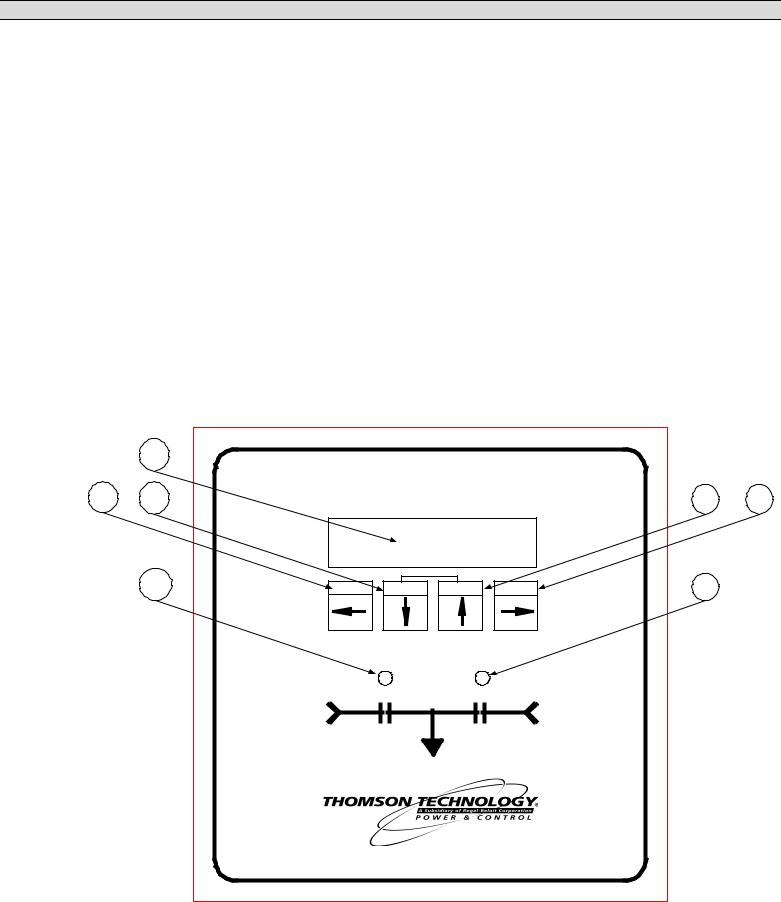
3.1.LEXAN FACEPLATE
The Lexan faceplate is shown as in FIGURE 7. The Lexan pushbuttons are connected to the main PCB via plug-in ribbon cable. The main features of the Lexan faceplate are described as follows with reference to FIGURE 7.
|
1 |
|
|
|
|
|
|
|
|
AUTOMATIC TRANSFER CONTROLLER |
|
||||
2 |
3 |
|
MODEL TSC 800 |
|
4 |
5 |
|
|
6 |
|
LAMP TEST |
|
|
|
|
|
EXIT |
DECREMENT |
INCREMENT |
ENTER |
7 |
|
|
|
|
UTILITY |
|
|
|
GENERATOR |
|
|
|
SUPPLY |
|
|
|
SUPPLY |
|
|
|
|
LOAD |
|
|
|
|
|
FULL FILENAME |
DRAWING1 |
|
|
DATE 02/04/04 11:58AM |
|
|
|
|
|
FIGURE# 7 |
|
|
|
|
PM 049 REV 9 06/04/24 |
12 |
Thomson Technology |

TSC 800 TRANSFER SWITCH CONTROLLER
LCD viewing window. The LCD display is mounted on the main PCB which is visible from the lexan faceplate.
EXIT pushbutton. The EXIT function is used to scroll backwards through the status menus or programming prompts to the previous item. The EXIT function is used to “exit” the programming menu by holding this button down for approximately 2 seconds while in the programming mode.
DECREMENT pushbutton. The DECREMENT function is used to change a programming value while in the programming mode. When this pushbutton is held down, the displayed value will be “decremented” to a lower value as desired. NOTE: The longer the pushbutton is held down, the faster the value will be decremented.
INCREMENT pushbutton. The INCREMENT function is used to change a programming value while in the programming mode. When this pushbutton is held down, the displayed value will be “incremented” to a higher value as desired. NOTE: The longer the pushbutton is held down, the faster the value will be incremented.
ENTER pushbutton. The ENTER function is used to scroll forwards through the status menus or programming prompts to the next item. The ENTER function is used to “enter” and accept new programming or operating mode changes after a new value has been selected (NOTE: Pressing the Exit button instead of the Enter button will reject the newly selected value and retain the original value). NOTE: In the programming mode, the longer the ENTER pushbutton is held down, the faster the next menu prompt will appear.
Load on Utility supply LED light viewing window
Load on Generator supply LED light viewing window
NOTE: A lamp test feature is provided to test all LED lights as well as the LCD display. To activate the lamp test feature, simultaneously push the INCREMENT and DECREMENT pushbuttons. All LEDs and LCD display pixels should illuminate for approximately 2 seconds then return to their original status. The Lamp Test feature is also used to clear active fault conditions and return the controller to normal operation.
NOTE: An active Timer Bypass feature is provided to allow a manual initiated bypass. To activate the feature, simultaneously push the DECREMENT and ENTER pushbuttons. The previously bypassed timer will operate normally during its next cycle. Refer to Timer Bypass section for related timers.
PM 049 REV 9 06/04/24 |
13 |
Thomson Technology |
TSC 800 TRANSFER SWITCH CONTROLLER
4 |
3 |
2 |
1 |
|
|
|
|
|
|
|
|
|
|
|
|
HD2 |
|
|
|
|
|
|
|
|
|
|
|
1 |
|
|
|
|
|
|
|
|
|
|
|
|
|
|
|
|
|
|
|
|
UTILIT Y SUPPLY |
|
|
GENERATOR SUPPLY |
HD1 |
2 |
|||||
|
|
|
|
TRANSFORMER |
|
|
TRANSFORMER |
3 |
||||||
|
|
|
|
|
|
|
||||||||
|
|
|
|
|
|
|
|
|
|
|
|
|
|
4 |
|
|
|
|
|
|
|
|
|
|
|
|
|
TB3 |
|
|
|
WATCHDOG |
|
|
|
|
|
|
|
|
|
1 |
|
|
|
|
|
|
|
|
|
|
|
|
|
|
|
||
|
|
ENGINE START |
|
|
|
|
|
|
|
|
|
|
||
|
|
TRANSFER |
|
|
|
|
|
|
|
|
|
|
|
|
|
|
TO UTILITY |
|
|
|
|
|
|
|
|
|
|
|
|
|
|
TRANSFER |
|
|
|
|
|
|
|
|
|
|
|
|
|
|
TO GENERATOR |
|
|
|
|
|
|
|
|
|
|
||
|
|
|
|
|
|
|
|
|
|
|
|
|
12 |
|
|
|
|
|
|
|
|
CONTRAST |
|
|
|
|
|||
|
|
|
|
|
|
|
|
|
|
|
|
|
TB2 |
|
|
|
|
|
|
|
|
|
|
|
|
|
|
1 |
|
|
|
|
|
|
|
|
|
|
|
|
|
|
1 |
|
|
|
|
J7 |
|
|
|
|
|
|
|
|
|
|
|
|
COMM |
|
|
|
|
|
|
|
|
|
|
|
|
|
|
RJ45 |
|
|
|
|
|
|
|
|
|
|
|
|
|
Connector |
|
|
|
|
|
|
|
|
|
|
|
|||
|
|
|
|
|
|
|
|
|
|
|
|
|
18 |
|
|
|
|
TB1 |
|
|
|
|
|
|
|
|
|
|
|
|
|
|
1 |
2 |
3 |
4 |
5 |
6 |
7 |
8 |
9 |
10 |
|
|
G;\ENGINEER\PRODUCTS\TSC800\852613b.VSD |
|
|
|
|
|
|
|
|
||||||
|
|
|
|
|
|
|
|
FIGURE # 8 |
|
|
||||
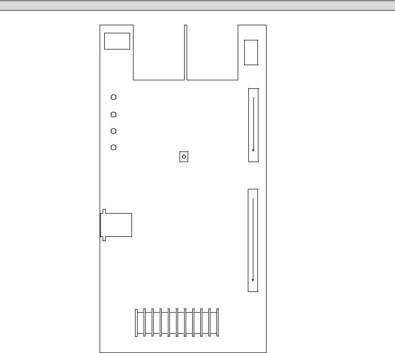
3.2.PRINTED CIRCUIT BOARD
The printed circuit board (PCB) is shown in FIGURE 8. The PCB contains the following user interface items:
3.2.1. POWER SUPPLY INPUT VOLTAGE SELECTION
The controller power supply input voltage level selection is made via two connector plugs, which are located on the PCB and are identified as HD1 and HD2. Voltage selection plug assemblies are unique for each power supply input level voltage
PM 049 REV 9 06/04/24 |
14 |
Thomson Technology |
TSC 800 TRANSFER SWITCH CONTROLLER
arrangement and must match the intended voltage level. Controller failure may result if incorrectly configured.
The TSC 800 is factory configured for a specific power supply voltage input as designated by voltage header plugs labeled as follows:
115V - designates a 115V power supply input voltage
230V - designates a 230V power supply input voltage
3.2.2. TERMINAL BLOCKS
Three terminal blocks are located on the PCB as follows:
TB1 High voltage sensing terminal block (120-600VAC)
|
|
WARNING |
|
|
|
Voltage sensing circuits are capable of lethal voltages while |
|
|
|
energized. Standard safety procedures should be followed and |
|
|
|
be performed by qualified personnel only. Failure to do so may |
|
|
|
cause personnel injury and/or death. |
|
|
|
|
|
TB2 |
Transfer control terminal block for output contacts and low voltage inputs |
||
TB3 |
Transfer control terminal block for 115/230v input and output circuits |
||
3.2.3. DIAGNOSTIC LEDs
The TSC 800 controller provides four diagnostic LED lights that are mounted on the rear of the printed circuit board as per FIGURE 8. Their functions are described as follows:
WATCHDOG |
This LED flashes on and off at irregular intervals that |
|
indicate that the microprocessor is functioning |
|
normally. |
ENGINE START |
This LED is illuminated whenever the TSC 800 is |
|
initiating an Engine Start (except when there is no |
|
power to the TSC 800 controller). |
TRANSFER TO UTILITY This LED is illuminated whenever the TSC 800 is initiating a Transfer to Utility signal.
TRANSFER TO GEN This LED is illuminated whenever the TSC 800 is initiating a Transfer to Generator signal.
NOTE: All LEDs will be illuminated whenever a lamp test function is performed.
PM 049 REV 9 06/04/24 |
15 |
Thomson Technology |

TSC 800 TRANSFER SWITCH CONTROLLER
3.2.4. COMMUNICATION PORT
A communication port is provided to interconnect to a remote communication system for remote monitoring and control of the transfer switch. Refer to Section 4 for additional information.
3.2.5. CONTRAST ADJUSTMENT
A contrast adjustment potentiometer is located on the PCB and is factory set for ambient temperatures of 15° to 30° Celsius. For different ambient temperatures, consult the factory for adjustment procedures.
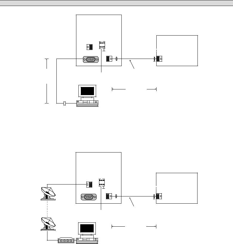
4.REMOTE COMMUNICATION
The TSC 800 transfer switch controller is available with a remote communication feature. The remote communication feature allows a TSC 800 controller to be monitored and controlled from a remote location via serial communication link to a personal computer (PC). PC’s may be connected locally via serial communication cable to the TSC 800 or remotely via modem and telephone systems. Remote communication can be via customer-supplied equipment or with an external communication interface module (CIM) as manufactured by Thomson Technology.
NOTE:
The CIM module may be located in the engine control panel provided the maximum distance between the CIM and TSC 800 controller is not exceeded as per the following information. Refer to the installation section of this manual for further information.
The CIM module utilizes an internal modem and contains ModbusTM protocol to interface with different remote monitoring software programs. Refer to separate literature for detailed information on the CIM module.
The TSC 800 communication port utilizes a RS422 data transmission signal that is directly interconnected to the CIM module via an 8 conductor, shielded cable with plug-in RJ45 connectors. Refer to FIGURES 9 & 10 for detailed information on direct connected or remote connected PC applications with CIM module.
TM |
Trademarks belong to their respective parties. |
|
NOTE: Both phone and serial communications ports can be connected at the same time. Doing so will result in no communication and/or possible CIM failure.
PM 049 REV 9 06/04/24 |
16 |
Thomson Technology |
TSC 800 TRANSFER SWITCH CONTROLLER
|
CIM |
|
||
|
Communication |
|||
|
Interface Module |
|||
|
Phone |
+- G |
TSC 800 |
|
|
|
|||
|
|
GRD |
||
|
no connection |
Transfer |
||
|
Port 2A |
Port 3B |
Controller |
|
|
|
|
GRD |
|
RS 232 Signal |
|
|
8 conductor |
|
DC Power |
Shielded Cable c/w |
|||
15M (50ft)** |
||||
RJ45 connectors |
||||
maximum |
|
8-35Vdc |
||
|
|
|||
cable length |
|
|
305M |
|
|
|
|
||
|
|
|
(1000ft)** |
|
|
|
|
maximum |
|
|
|
|
cable length |
|
null modem |
Personal |
|
**Communication cable wiring must be suitably routed to |
|
connector |
|
protect it from sources of electrical interference. Refer to |
||
|
Computer |
|
||
|
|
installation section for further information. |
||
|
|
|
||
|
|
|
G:\ENGINEER\PRODUCTS\TSC800\852621.VSD |
|
FIGURE #9 TSC 800 WITH CIM MODULE & DIRECT CONNECTED PC (RS232)
|
CIM |
|
|
|
Communication |
||
|
Interface Module |
||
|
Phone |
+- G |
TSC 800 |
|
|
||
|
|
|
|
|
|
GRD |
Transfer |
|
Port 2A |
Port 3B |
Controller |
|
|
|
GRD |
|
no connection |
|
|
|
|
|
8 conductor |
|
DC Power |
Shielded Cable c/w |
|
|
RJ45 connectors |
||
|
|
8-35Vdc |
|
|
|
|
|
|
|
|
305M (1000ft)** |
|
|
|
maximum |
|
|
|
cable length |
|
|
|
**Communication cable wiring must be suitably routed to |
Modem |
Personal |
|
protect it from sources of electrical interference. Refer to |
|
installation section for further information. |
||
|
Computer |
|
|
|
|
|
|
G:\ENGINEER\PRODUCTS\TSC800\852622.VSD
FIGURE #10 TSC 800 WITH CIM MODULE & REMOTE CONNECTED PC
PM 049 REV 9 06/04/24 |
17 |
Thomson Technology |
TSC 800 TRANSFER SWITCH CONTROLLER
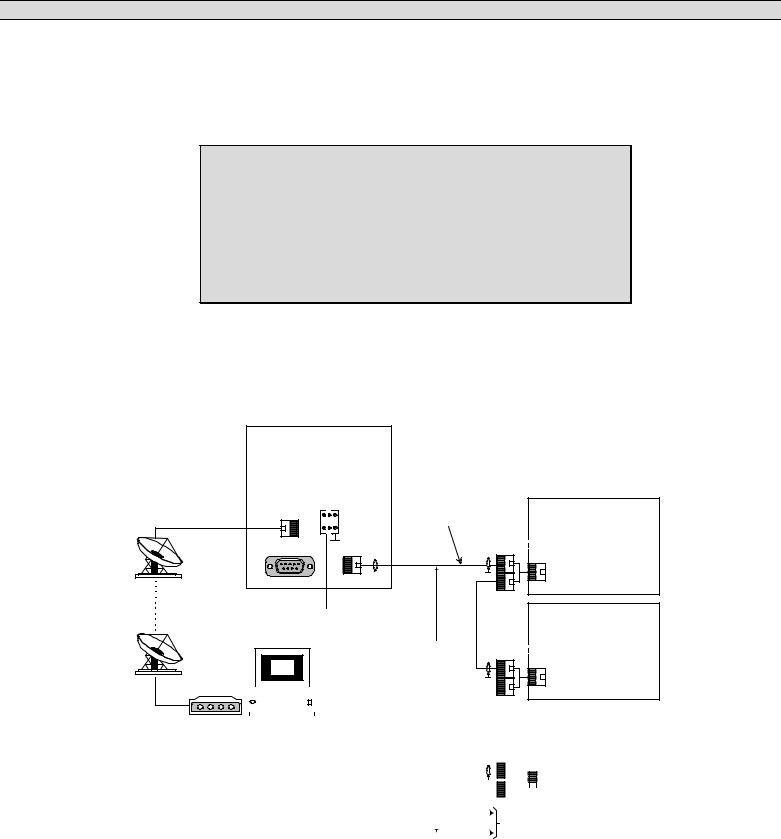
The TSC 800 RS422 communication port allows multiple TSC 800 controllers to be directly interconnected together to form a single network system. Up to 10 TSC 800 controllers may be interconnected to a single CIM module.
NOTE:
TSC 800 controllers and MEC 20 engine-generator controllers may be interconnected together via the same communication network provided the maximum number of controllers and interconnection distances are not exceeded. For additional information, refer to associated product instruction manuals.
Each TSC 800 controller is programmed with a unique communication node address number for the remote communication system to reference. The network system may be connected to a local PC or to a remote PC via telephone system and CIM module. Refer to FIGURE #11 for a typical TSC 800 network system with CIM module.
CIM |
|
|
|
|
Communication |
|
|
|
|
Interface Module |
8 conductor |
|
|
|
Phone |
+- G |
Shielded Cable c/w |
TSC 800 |
|
|
RJ45 connectors |
|||
|
|
|||
|
GRD |
|
|
Transfer |
|
|
|
Controller |
|
Port 2A |
Port 3B |
|
|
|
|
|
|
GRD |
#1 |
no connection |
|
|
|
|
DC Power |
|
|
TSC 800 |
|
|
8-35Vdc |
|
|
|
|
|
|
Transfer |
|
|
|
305M |
|
|
THS |
|
(1000ft)** |
|
Controller |
|
maximum |
|
#2 |
|
|
|
cable length |
GRD |
|
|
|
|
|
|
|
|
|
|
|
|
|
|
|
|
|
|
|
|
|
|
|
|
|
|
|
|
|
|
|
|
|
|
|
|
|
|
|
|
|
|
|
|
|
|
|
|
|
|
|
|
|
|
|
|
|
|
|
|
|
|
|
|
|
Modem |
|
|
|
Personal |
|
|
|
|
|
|
|
|
|
|
|
|
|
|
TSC 800 |
||||||||||||
|
|
|
|
Computer |
|
|
|
|
|
|
|
|
|
|
|
Transfer |
|||||||||||||||
|
|
|
|
|
|
|
|
|
|
|
|
|
|
|
|
|
|
|
|
|
|
|
|
|
|
|
|
|
|
|
|
|
|
|
|
|
|
|
|
|
|
|
|
|
|
|
|
|
|
|
|
|
|
|
|
|
|
|
|
|
|
|
Controller |
|
|
|
|
|
|
|
|
|
|
|
|
|
|
|
|
|
|
|
|
|
|
|
|
|
|
|
|
|
|
|
|
|
|
|
|
|
|
|
|
|
|
|
|
|
|
|
|
|
|
|
|
|
|
|
|
|
|
|
|
|
|
|
|
|
|
|
|
|
|
|
|
|
|
|
|
|
|
|
|
|
|
|
|
|
|
|
|
|
|
|
|
|
|||
|
|
|
|
|
|
|
|
|
|
|
|
|
|
|
|
|
|
|
|
|
|
|
|
|
|
|
|
|
|
|
|
|
|
|
|
|
|
|
|
|
|
|
|
|
|
|
|
|
|
|
|
|
|
|
|
|
|
|
|
|
|
|
#3 |
**Communication cable wiring must be |
|
|
GRD |
|
|
|
|
|
|
|
|||||||||||||||||||||
|
|
|
|
|
|
|
|
|
|
|
|
||||||||||||||||||||
suitably routed to protect it from sources of |
|
|
|
|
|
|
|
|
|
|
|
|
|||||||||||||||||||
|
|
|
|
|
|
|
|
|
|
|
|||||||||||||||||||||
electrical interference. Refer to installation |
|
|
|
|
To additional TSC 800 controllers |
||||||||||||||||||||||||||
|
|
|
|||||||||||||||||||||||||||||
section for further information. |
|
|
|
|
|
||||||||||||||||||||||||||
|
|
|
|
(maximum 10 total per network) |
|||||||||||||||||||||||||||
|
|
|
|
|
|
|
|
|
|
|
|
|
|
|
|
|
|
|
|
|
|
|
|
||||||||
|
|
|
|
|
|
|
|
|
|
|
|
|
|
|
|
|
|
|
|
|
|
|
|
||||||||
|
|
|
|
|
|
|
|
|
|
|
|
|
|
|
|
|
|
|
|
|
|
|
G:\ENGINEER\PRODUCTS\TSC800\852623.VSD |
||||||||
FIGURE #11 NETWORKED TSC 800 INTERCONNECTION DIAGRAM
PM 049 REV 9 06/04/24 |
18 |
Thomson Technology |
TSC 800 TRANSFER SWITCH CONTROLLER
5.TSC 800 DISPLAY MENUS
The TSC 800 contains a Liquid Crystal Display (LCD) that is visible on the front faceplate. The LCD has pre-programmed display menus which are automatically displayed in an auto-Scrolling mode or they may be selected manually by pressing the ENTER or EXIT pushbuttons in succession until the desired menu is displayed. The display menu types and order in which they are programmed are as follows:
NOTE:
The following display menus are provided in TSC 800 Software version 2.0 (or higher).
SYSTEM TIME |
|
|
|
||
STATS MENU |
|
|
|
||
ATS MODE MENU |
|
|
|
||
PROGRAM MENU |
|
|
|
||
SYSTEM STATUS |
|
TIMER COUNTDOWN |
|
||
|
|
||||
|
|
|
|
|
|
|
|
|
|
|
|
UTILITY SUPPLY MENU |
|
|
|
||
GEN SUPPLY MENU |
|
|
|
||
NOTE: ATS MODE MENU access may be inhibited. Refer to programming instruction for further details.
5.1.SYSTEM TIME MENU
The system time menu is used to show current system time and week number. The TSC 800 controller uses its internal time clock to reference when an automatic exercising operation (if pre-programmed) is to occur. To change the system time, refer to the “time clock adjustment” section of this manual.
NOTE:
The following system Time menu is provided in TSC 800
Software version 2.0 (or higher).
PM 049 REV 9 06/04/24 |
19 |
Thomson Technology |

TSC 800 TRANSFER SWITCH CONTROLLER
LCD DISPLAY
System Time
Mon 1 12:24:31
Displays the day of the week (e.g. Monday)
Displays the week number (e.g. 1-4)
Displays the current time in hours (24-hour clock): hour: min: seconds
5.2.ATS MODE MENU
The ATS Mode Menu provides manually selectable operating modes which includes On/Offload testing features (comparable features also available via external inputs utilizing an optional FTS4 selector switch). The Internal and External ATS Mode inputs operate in a parallel fashion; the Mode of Operation will be determined by the highest priority selected by either format. The priority levels are as follows (highest to lowest priority):
1)Off (Controller out of Service, no control logic applied)
2)Onload Test
3)Offload Test
4)Auto
A utility power failure will over ride all but “Off”. In the event of a generator failure and the utility supply is available and considered normal, the ATS will return to the utility supply except when “Off” selected.
NOTE:
The following test menu is provided in TSC 800 Software version 2.0 (or higher).
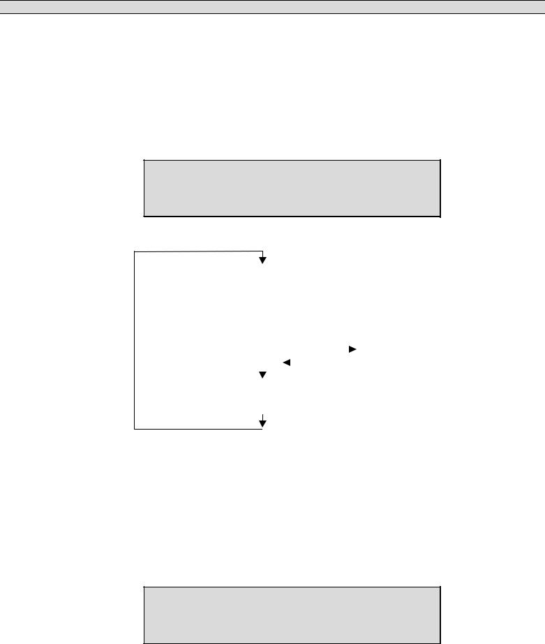
The ATS Mode sub-menus are organized as follows:
ATS Mode Menu |
|
|
No |
|
|
|
|
|
|
|
|
|
|
|
|
|
|
|
|||
|
|
|
Yes |
|
|
Auto (Automatic Operation & Programmed Test Mode) |
||||
|
|
|
|
|
||||||
|
|
|
|
|
|
Offload Test |
|
Continuous Test |
|
|
|
|
|
|
|
|
|
|
|||
|
|
|
|
|
|
Onload Test |
|
|
|
|
|
|
|
|
|
|
|
|
|
|
|
|
|
|
|
|
|
Off (Controller Disabled) |
Timed Test: Selectable |
|||
|
|
|
|
|
|
|||||
|
|
|
|
|
|
|
|
|
15 - 240 Min. |
|
Automatic Return to “Auto Mode”
PM 049 REV 9 06/04/24 |
20 |
Thomson Technology |

TSC 800 TRANSFER SWITCH CONTROLLER
LCD DISPLAY
ATS Mode Menu
No
Displays two messages that may be toggled between YES or NO by pressing the INCREMENT or DECREMENT pushbuttons. Their functions are described as follows:
No |
Status message only, a change is required to gain access. |
Yes |
The required variable to be entered to gain access and proceed. If the |
|
password protect feature is enabled a prompt will appear requiring a |
|
level 2 or greater security code be entered to allow a read-write access. |
|
Entering a level 1 password will only permit a read only access. |
The following ATS Mode Menu options are provided:
Auto This is the Default Selection and is required to enable all automatic features of the controller. In this mode the TSC 800 Controller will automatically transfer the load to the appropriate source based on availability (the Utility supply is considered the preferred source). The TSC 800 will provide automatic timed testing if enabled in programming. Manual testing is disabled when the Auto ATS mode is selected (NOTE: the external mode inputs input will over ride ATS Mode Menu selected Auto mode).
Offload Test When the Offload Test prompt is selected and entered, the generator will immediately start and operate offload and will not permit a load transfer. The test menu will display Continuous Test, to select a timed test use the INCREMENT or DECREMENT pushbutton to scroll and select a test duration time, press enter to accept the time (selectable in 15 minutes increments from 15 – 240 min.). The generator will remain running until a different mode is selected and entered or the timed test duration expires (selecting Auto will immediately terminate the test). On expiry of the timed test the operating mode automatically reverts to Auto.
NOTE: If the Utility supply fails during this test mode, the load will automatically transfer to the generator if within acceptable limits.
PM 049 REV 9 06/04/24 |
21 |
Thomson Technology |
 Loading...