


TSC 80
TRANSFER SWITCH CONTROLLER
INSTALLATION, OPERATING &
SERVICE MANUAL
Software Version 2.2
PM063 Rev 7 09/02/27
9087A – 198th Street, Langley, BC Canada V1M 3B1 Telephone (604) 888-0110 Telefax (604) 888-3381 E-Mail: info@thomsontechnology.com www.thomsontechnology.com

TSC 80 TRANSFER SWITCH CONTROLLER
|
TABLE OF CONTENTS |
|
1. |
INTRODUCTION |
1 |
|
1.1. PRODUCT REVISION HISTORY |
1 |
|
1.2. GENERAL INFORMATION |
2 |
|
1.3. SERVICE DISPLAY MODULE (SDM) |
3 |
|
1.4. NOTES TO TRANSFER SWITCH INSTALLER |
3 |
|
1.4.1. SYSTEM VOLTAGE |
3 |
|
1.4.2. SYSTEM PHASING-HIGH LEG DELTA SYSTEMS |
3 |
|
1.4.3. REMOTE START CONTACT FIELD WIRING |
4 |
|
1.4.4. DIELECTRIC TESTING |
5 |
2. |
DESCRIPTION |
6 |
|
2.1. LEXAN FACEPLATES |
6 |
|
2.2. PRINTED CIRCUIT BOARD |
8 |
|
2.2.1. TERMINAL BLOCKS |
8 |
|
2.2.2. DIAGNOSTIC LED’S |
9 |
|
2.2.3. ADJUSTMENT POTENTIOMETERS |
10 |
|
2.2.4. CONFIGURATION JUMPERS |
10 |
|
2.3. TSC 80 CONTROLLER FEATURES |
10 |
|
2.4. APPLICATION INFORMATION |
11 |
|
2.4.1. AC VOLTAGE SENSING INPUT |
11 |
|
2.4.2. AC CONTROL POWER INPUT |
13 |
|
2.4.3. OUTPUTS |
13 |
3. |
OPERATING INSTRUCTIONS |
14 |
|
3.1. AUTOMATIC SEQUENCE OF OPERATION |
14 |
|
3.1.1. NORMAL OPERATION |
14 |
|
3.1.2. ABNORMAL OPERATION |
15 |
|
3.2. TEST MODES |
17 |
|
3.2.1. UTILITY POWER FAIL SIMULATION (LOAD TEST) |
17 |
|
3.2.2. AUTOMATIC PLANT EXERCISE TEST |
18 |
|
3.2.3. FOUR FUNCTION REMOTE TEST (FTS4 OPTION) |
19 |
|
3.2.4. REMOTE TEST |
20 |
|
3.3. TRANSFER FAIL FAULT RESET |
20 |
|
3.4. LAMP TEST |
20 |
|
3.5. TIMER BYPASS |
21 |
PM063 Rev 7 09/02/27 |
Thomson Technology |

TSC 80 TRANSFER SWITCH CONTROLLER
4. |
TSC 80 CONFIGURATION INSTRUCTIONS |
22 |
4.1. CONFIGURATION JUMPERS |
22 |
|
|
4.1.1. SYSTEM VOLTAGE |
22 |
|
4.1.2. SYSTEM FREQUENCY |
25 |
|
4.1.3. SYSTEM PHASES |
25 |
|
4.1.4. GEN EXERCISE LOAD TEST MODE (NO XFER) |
26 |
|
4.1.5. SECURE |
26 |
4.2. TSC 80 ADJUSTMENT POTENTIOMETERS |
27 |
|
|
4.2.1. UTILITY UNDER VOLTAGE SETPOINT |
28 |
|
4.2.2. GENERATOR UNDERVOLTAGE SETPOINT |
29 |
|
4.2.3. GENERATOR UNDER FREQUENCY SETPOINT |
29 |
|
4.2.4. ENGINE START DELAY |
30 |
|
4.2.5. ENGINE WARMUP DELAY |
31 |
|
4.2.6. ENGINE COOLDOWN DELAY |
31 |
|
4.2.7. UTILITY RETURN DELAY |
31 |
|
4.2.8. NEUTRAL DELAY |
31 |
5. |
TSC 80 TYPICAL CONNECTION DIAGRAM |
32 |
6. |
TSC 80 SPECIFICATIONS |
33 |
7. |
TROUBLESHOOTING |
34 |
8. |
TSC 80 REPLACEMENT PARTS |
36 |
9. |
PRODUCT RETURN POLICY |
36 |
10. |
NOTES |
37 |
PM063 Rev 7 09/02/27 |
Thomson Technology |

TSC 80 TRANSFER SWITCH CONTROLLER
1.INTRODUCTION
1.1.PRODUCT REVISION HISTORY
The following information provides an historical summary of changes made to this product
since the original release.
Software Version
1.0 04/11/19 |
Original version |
|
|
|
|
1.1 05/05/10 |
Software updated to incorporate the following: |
|
|
|
Revise potentiometer control directions to match revised |
|
|
printed circuit board silkscreen text. |
|
|
Change operation associated to “secure” configuration |
|
|
jumper. Enable remote load test to be activated if secure |
|
|
jumper is ON. |
|
|
|
1.2 05/10/31 |
Beta Test Software-Not released for production |
|
|
|
|
1.3 05/11/05 |
Software updated to change some internal default timer settings |
|
|
|
|
2.0 08/08/14 |
Software updated to incorporate TSC 80e Option |
|
|
|
|
2.1 09/01/01 |
Software updated to incorporate Configurable PT Ratio for TSC |
|
|
|
80e Option |
|
|
|
2.2 09/02/27 |
Software revised to correct 7-Day Genset Exercise Operation in |
|
|
|
TSC 80 Controllers utilizing version 2.0 and 2.1software. |
|
|
|
Operating & Service Manual Version |
||
|
|
|
|
Rev 0 04/11/19 |
Original release |
|
|
|
|
Rev 1 05/05/10 |
The following changes have been incorporated: |
C |
Add changes for revised TSC 80 Software version 1.1. |
|
|
|
|
o |
Add new Environmental Section |
|
|
|
|
n |
Miscellaneous changes |
|
|
|
|
|
|
|
|
t Rev 2 05/12/15 |
Add changes for revised TSC 80 Software version 1.3. |
aRev 3 08/08/01 |
Add changes for TC80e Option |
|
c |
Revised Default Settings for TSC 80E |
|
|
Rev 4 08/08/18 |
|
t |
Manual changed to dedicated TSC 80 manual (removed TSC 80E |
|
|
Rev 5 09/01/01 |
|
|
|
references) |
|
|
|
Thomson Technology, to obtain applicable instruction manuals. Soft copy of most current
version is available at www.thomsontechnology.com.
PM063 Rev 7 09/02/27 |
1 |
Thomson Technology |
TSC 80 TRANSFER SWITCH CONTROLLER
1.2.GENERAL INFORMATION
The following information is provided for general information only pertaining to TSC 80 transfer switch controllers. For information on the TSC 80e controller refer to product manual PM091.
NOTE:
Installations should be done in accordance with all applicable electrical regulation codes as required.
The following information is provided for general information only pertaining to TSC 80 transfer switch controllers installed in a Thomson Technology Automatic Transfer Switch as applied in a typical site installation. For specific site installation information, consult Thomson Technology as required.
CAUTION
contents subject to damage by
STATIC ELECTRICITY
This equipment contains static-sensitive parts. Please observe the following anti-static precautions at all times when handling this equipment. Failure to observe these precautions may cause equipment failure and/or damage.
•Discharge body static charge before handling the equipment (contact a grounded surface and maintain contact while handling the equipment, a grounded wrist strap can/should also be utilized).
•Do not touch any components on the printed circuit board with your hands or any other conductive equipment.
•Do not place the equipment on or near materials such as Styrofoam, plastic and vinyl. Place the equipment on grounded surfaces and only use an anti-static bag for transporting the equipment.
PM063 Rev 7 09/02/27 |
2 |
Thomson Technology |

TSC 80 TRANSFER SWITCH CONTROLLER
1.3.SERVICE DISPLAY MODULE (SDM)
An optional hand held, plug-in Service Display Module (SDM) is available for the TSC 80 Transfer Controller. The SDM module provides an LCD screen to display additional detailed information on the operation and settings of the TSC 80 controller for simplified servicing/trouble shooting procedures. For detailed information, refer to the separate SDM module instruction manual (PM065).
1.4.NOTES TO TRANSFER SWITCH INSTALLER
1.4.1. SYSTEM VOLTAGE
If the transfer switch has programmable/multi-tap system voltage capability (refer to electrical schematic), confirm the transfer switch has been configured for the correct system voltage. If the transfer switch requires reconfiguring, the TSC 80 controller will require reconfiguration as well.
WARNING
Failure to confirm and match transfer switch voltage with the system voltage could cause serious equipment damage.
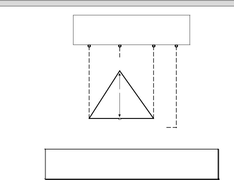
1.4.2. SYSTEM PHASING-HIGH LEG DELTA SYSTEMS
When the transfer switch is connected to 3 phase 4 wire delta systems, the “High” leg (Phase B, colored Orange), must be connected to Phase B of the Utility and/or Generator supply. This will ensure the ATS control power which is internally connected between phase A and neutral is maintained at 120VAC. Refer to figure below for further details.
WARNING
Failure to match correct system phasing
will result in serious damage to the
TSC 80 controller.
PM063 Rev 7 09/02/27 |
3 |
Thomson Technology |
TSC 80 TRANSFER SWITCH CONTROLLER
Automatic Transfer
Switch (Utility Supply)
PH A |
PH B |
PH C |
Neural |
(UA) |
(UB) |
(UC) |
(N) |
B
(Orange)
(High Leg)
240V |
208V |
240V |
A |
120V |
|
|
|
|
120V |
|
|
|
|
|
C |
||||
|
||||||||||||||||
(Red) |
|
|
|
|
|
|
|
|
|
|
|
|
|
(Yellow) |
||
|
|
|
|
|
|
|
|
|
|
|
|
|
||||
|
|
|
|
|
|
|
|
|
|
|
|
|
|
|
|
|
N
(W hite)
CAUTION!!!
All installation and/or service work performed must be done by qualified personnel only. Failure to do so may cause personal injury or death.
1.4.3. REMOTE START CONTACT FIELD WIRING
As a minimum, the remote engine start control field wiring shall conform to the local regulatory authority on electrical installations. Field wiring of a remote start contact from a transfer switch to a control panel should conform to the following guidelines to avoid possible controller malfunction and/or damage.
PM063 Rev 7 09/02/27 |
4 |
Thomson Technology |

TSC 80 TRANSFER SWITCH CONTROLLER
1.4.3.1.Minimum #14 AWG (2.5mm2) wire size shall be used for distances up to 100ft (30m)1). For distances exceeding 100 ft. (30m) consult Thomson Technology.
1.4.3.2.Remote start contact wires should be run in a separate conduit.
1.4.3.3.Avoid wiring near AC power cables to prevent pick-up of induced voltages.
1.4.3.4.An interposing relay may be required if field-wiring distance is excessively long (i.e. greater than 100 feet (30m)) and/or if a remote contact has a resistance of greater than 5.0 ohms.
1.4.3.5.The remote start contact must be voltage free (i.e. dry contact). The use of a “powered” contact will damage the transfer controller.
1.4.4. DIELECTRIC TESTING
Do not perform any high voltage dielectric testing on the transfer switch with the TSC
80controller connected into the circuit as serious damage will occur to the controller.
All AC control fuses and control circuit isolation plugs connected to the TSC 80 must
be removed if high voltage dielectric testing is performed on the transfer switch.
PM063 Rev 7 09/02/27 |
5 |
Thomson Technology |

TSC 80 TRANSFER SWITCH CONTROLLER
2.DESCRIPTION
The TSC 80 controller utilizes microprocessor-based design technology, which provides high accuracy for all voltage sensing and timing functions. The TSC 80 is factory configured to control all the operational functions and display features of the automatic transfer switch.
The TSC 80 controller consists of two parts; a Lexan faceplate, which is mounted externally on the transfer switch door, and a printed circuit board (PCB), which is mounted inside the transfer switch on the enclosure door.
2.1.LEXAN FACEPLATES
The TSC 80 Controller Lexan faceplate is shown as in FIGURE 1. The Lexan pushbuttons and LED lights are connected to the main PCB via plug-in ribbon cable. The main features of the Lexan faceplate are described as follows with reference to FIGURE 1.
Utility Supply Available LED light
Load on Utility supply LED light
Load on Generator supply LED light
Generator Supply Available LED light
ATS Load Bus Energized LED light
Utility Power Fail Test Mode Pushbutton & LED light
Auto Generator Exercise Mode Pushbutton & LED light
PM063 Rev 7 09/02/27 |
6 |
Thomson Technology |
TSC 80 TRANSFER SWITCH CONTROLLER
FIGURE 1- TSC 80 Controller Lexan Faceplate
PM063 Rev 7 09/02/27 |
7 |
Thomson Technology |

TSC 80 TRANSFER SWITCH CONTROLLER
2.2.PRINTED CIRCUIT BOARD
38 |
|
600V |
|
|
|
TSC 80e |
|
|
|
37 |
|
|
480V |
|
|
|
|
|
|
||||
|
|
|
|
|
ONLY |
|
|
|
|
||
|
|
380V |
|
|
|
PROG 2 |
|
|
|||
|
|
|
|
|
|
|
|
|
|
|
|
|
|
240V |
|
|
|
|
|
|
|
|
|
|
|
50HZ |
|
|
|
|
|
|
|
|
|
|
|
1 Phase |
|
|
|
|
|
PROG 3 |
|
|
|
|
|
|
|
|
|
|
|
|
|
|
|
|
|
No Xfer |
|
|
|
|
|
|
|
|
|
|
|
Secure |
|
|
|
|
|
|
|
|
|
|
JP5 |
|
|
|
|
|
|
PROG 1 |
|
|
|
44 |
TB7 |
|
|
|
|
|
|
|
|
TB6 |
29 |
|
|
|
|
|
|
|
|
|
|
|
|
Gen |
|
|
|
|
|
Utility UV |
|
|
|
|
|
Warm-up |
|
|
|
|
|
|
|
|
|
||
|
|
|
|
|
|
ENG STOP |
|
28 |
|||
|
|
|
|
|
|
|
|
|
|||
Gen UV |
|
|
|
|
Neutral |
|
|
|
|
1 |
|
|
|
|
|
|
|
|
|
|
|||
|
|
|
|
Delay |
|
|
|
|
|
||
|
|
|
|
|
|
|
|
|
|
|
|
Gen Freq |
|
|
|
Utility Return |
TRANSFORMER |
|
|
||||
|
|
|
|
|
|
|
|
|
|||
Gen Start |
|
|
|
|
Gen |
|
|
|
|
|
|
|
|
|
|
Cooldown |
|
|
|
|
|
||
|
|
|
|
|
|
|
|
|
|
|
|
BT1 |
|
|
|
|
|
TRANSFORMER |
|
|
|||
|
|
|
|
|
|
|
|
|
|
||
|
REAL TIME |
|
|
|
|
|
|
XFER UTIL |
|
|
|
|
CLOCK |
|
|
|
|
SYS OK |
|
|
|
|
|
|
BATTERY |
|
|
|
|
|
|
XFER GEN |
|
|
|
|
(TSC80e only) |
|
|
|
|
|
|
|
|||
|
|
|
|
|
|
|
|
|
|
||
|
|
|
|
|
|
|
|
LD ON GEN |
|
|
|
|
|
|
|
|
|
|
|
LD ON UTIL |
|
|
|
|
|
|
|
|
|
|
|
|
|
|
11 |
|
|
|
|
|
|
|
|
|
|
|
TB2-5 |
|
1 |
2 |
3 |
4 |
5 |
6 |
7 |
8 |
9 |
10 |
|
TB1 |
|
|
|
|
|
|
|
|
|
|
|
FIGURE 2
The printed circuit board (PCB) is shown in FIGURE 2. The PCB contains the following user
interface items:
2.2.1. TERMINAL BLOCKS
Terminal blocks are located on the PCB as follows:
TB1 high voltage sensing terminal block (120-600VAC).
WARNING
PM063 Rev 7 09/02/27 |
8 |
Thomson Technology |

TSC 80 TRANSFER SWITCH CONTROLLER
Voltage sensing circuits are capable of lethal voltages while energized. Standard safety procedures should be followed and be performed by qualified personnel only. Failure to do so may cause personnel injury and/or death.
TB2-6 transfer control terminal block for 115VAC control power and input/output circuits.
TB7 low voltage (5Vdc) control inputs.
2.2.2. DIAGNOSTIC LED’S
The TSC 80 controller provides diagnostic LED lights, which are mounted on the printed circuit board as per FIGURE 2. Their functions are described as follows:
SYS OK |
This LED flashes on and off at irregular intervals, which |
|
indicates the microprocessor is functioning normally. |
TRANSFER TO UTILITY This LED is illuminated whenever the TSC 80 is initiating a signal to transfer to the Utility supply.
TRANSFER TO GEN |
This LED is illuminated whenever the TSC 80 is initiating a |
|
signal to transfer to the Generator supply. |
ENGINE STOP |
This LED is illuminated whenever the TSC 80 is initiating an |
|
Engine STOP signal. |
PM063 Rev 7 09/02/27 |
9 |
Thomson Technology |
 Loading...