


TS 880
AUTOMATIC TRANSFER SWITCHES
INSTALLATION, OPERATING &
SERVICE MANUAL
PM064 REV 8 10/01/25
9087A – 198th Street, Langley, BC Canada V1M 3B1 Ÿ Telephone (604) 888-0110 Telefax (604) 888-3381 Ÿ E-Mail: info@thomsontechnology.com Ÿ www.thomsontechnology.com

TS 880 TRANSFER SWITCH
TABLE OF CONTENTS
1. |
PRODUCT REVISION HISTORY |
1 |
|
2. |
EQUIPMENT STORAGE |
1 |
|
|
2.1. |
ENVIRONMENTAL CONDITIONS |
1 |
|
|
2.1.1. EQUIPMENT STORAGE |
2 |
|
|
2.1.2. EQUIPMENT OPERATING |
2 |
3. |
NOTES TO INSTALLER |
2 |
|
|
3.1. UPSTREAM CIRCUIT PROTECTIVE DEVICES/ELECTRICAL CONNECTIONS |
2 |
|
|
3.2. TRANSFER SWITCHES WITH INTEGRAL OVER CURRENT PROTECTION |
3 |
|
|
3.3. TRANSFER SWITCHES WITH MULTI-TAP VOLTAGE CAPABILITY |
3 |
|
|
3.4. SYSTEM PHASING-HIGH LEG DELTA SYSTEMS |
4 |
|
|
3.5. REMOTE START CONTACT FIELD WIRING |
5 |
|
|
3.6. |
DIELECTRIC TESTING |
6 |
|
3.7. MOUNTING OF ENCLOSED TRANSFER SWITCHES |
6 |
|
4. |
GENERAL DESCRIPTION |
9 |
|
|
4.1. |
PRODUCT MODEL CODE |
10 |
|
4.2. |
TYPICAL COMMISSIONING PROCEDURES |
11 |
5. GENERAL THEORY OF OPERATION |
11 |
||
|
5.1. STANDARD AUTOMATIC TRANSFER SWITCH |
11 |
|
|
|
5.1.1. NORMAL SEQUENCE OF OPERATION - OPEN TRANSITION |
11 |
|
|
5.1.2. NORMAL SEQUENCE OF OPERATION - CLOSED TRANSITION |
12 |
|
5.2. SERVICE ENTRANCE AUTOMATIC TRANSFER SWITCH |
16 |
|
|
|
5.2.1. NORMAL OPERATION |
16 |
|
|
5.2.2. OVER CURRENT TRIP |
17 |
|
|
5.2.3. SERVICE DISCONNECT PROCEDURE |
17 |
|
|
5.2.4. ADDITIONAL PROCEDURES |
19 |
|
5.3. |
TEST MODES |
21 |
PM064 REV 8 10/01/25 |
Thomson Technology |
|
|

TS 880 TRANSFER SWITCH
6. OVER CURRENT PROTECTION |
21 |
6.1. STANDARD TS 880 AUTOMATIC TRANSFER SWITCH |
22 |
6.2.OPTIONAL TS 880 AUTOMATIC TRANSFER SWITCH WITH INTEGRAL OVER
CURRENT PROTECTION |
22 |
7. SERVICING TRANSFER SWITCH MECHANISMS |
23 |
7.1.SERVICING –100A-250A S STYLE MOLDED CASE SWITCH TYPE TRANSFER
MECHANISMS |
23 |
7.1.1. GENERAL DESCRIPTION |
23 |
7.1.2. EQUIPMENT INSPECTION |
24 |
7.1.3. MANUAL OPERATION |
24 |
7.1.4. RECOMMENDED MAINTENANCE |
25 |
7.2. SERVICING– 400A-1200A MOLDED CASE TYPE TRANSFER MECHANISMS |
26 |
7.2.1. GENERAL DESCRIPTION |
26 |
7.2.2. EQUIPMENT INSPECTION |
27 |
7.2.3. MANUAL OPERATION |
28 |
7.2.4. RECOMMENDED MAINTENANCE |
28 |
7.3.SERVICING – 800A – 4000A INSULATED CASE TYPE TRANSFER MECHANISMS
|
29 |
7.3.1. GENERAL DESCRIPTION |
30 |
7.3.2. EQUIPMENT INSPECTION |
30 |
7.3.3. MANUAL OPERATION |
31 |
7.3.4. RECOMMENDED MAINTENANCE |
32 |
8.FRONT VIEW (TYPICAL) 3 POLE 100A-250A S STYLE TRANSFER MECHANISM 33
9.FRONT VIEW (TYPICAL) 3 POLE 400A-1200A T STYLE TRANSFER MECHANISM 34
10.FRONT VIEW (TYPICAL) 3 POLE 800A-4000A INSULATED CASE TYPE
TRANSFER MECHANISM |
35 |
|
11. |
CONNECTION CONFIGURATION OPTIONS |
36 |
12. |
CABLE TERMINAL INFORMATION |
37 |
13. |
REQUIREMENTS FOR UPSTREAM CIRCUIT PROTECTIVE DEVICES |
38 |
PM064 REV 8 10/01/25 |
Thomson Technology |
|
|

TS 880 TRANSFER SWITCH
13.1. WITHSTAND CURRENT RATINGS (ALL MODELS WITHOUT INTEGRAL
|
OVERCURRENT PROTECTION OPTION) |
38 |
|
13.2. INTERRUPTING CAPACITY CURRENT RATINGS (ALL MODELS WITH INTEGRAL |
|
|
OVERCURRENT PROTECTION OPTION) |
39 |
14. |
GROUND FAULT SITE TEST REQUIREMENTS |
39 |
|
14.1. PERFORMANCE TEST |
40 |
15. |
TROUBLESHOOTING (100A-1200A MOLDED CASE SWITCH TYPE ATS) |
40 |
16. |
TROUBLESHOOTING (800A-4000A INSULATED CASE SWITCH TYPE ATS) |
43 |
17. |
POWER SWITCHING DEVICE TROUBLESHOOTING (800A-4000A INSULATED |
|
CASE SWITCH TYPE ATS) |
45 |
|
18. |
POWER SWITCHING DEVICE DRAWING |
47 |
19. |
DRAWOUT CHASSIS ENGINEERING DRAWING |
48 |
20. |
ELECTRICAL DIAGRAMS |
49 |
21. |
REPLACEMENT PARTS |
52 |
22. |
PRODUCT RETURN POLICY |
53 |
23. |
NOTES |
54 |
24. |
PERFORMANCE TEST FORM |
55 |
PM064 REV 8 10/01/25 |
Thomson Technology |
|
|

TS 880 TRANSFER SWITCH
1.PRODUCT REVISION HISTORY
The following information provides an historical summary of changes made to this product since the original release.
Operating & Service Manual Version
Rev 0 04/11/15 |
Original release. |
|
|
Rev1 04/12/21 |
Additional information for Closed Transition Operation |
|
|
Rev 2 05/03/08 |
Changes to incorporate reversing style ATS motor for 100-250A |
|
transfer switches |
|
|
Rev 3 05/05/11 |
Changes to Section 5 & Section 21. |
|
|
Rev 4 06/05/08 |
Changes to Section 13. |
|
|
Rev 5 07/02/01 |
Changes to Section 13. |
|
|
Rev 6 07/02/27 |
Changes to Section 12, Cable Terminal Information |
|
|
Rev 7 08/03/05 |
Changes to Incorporate new S-Style mechanism (100A, 150A, |
|
200A, 250A) |
|
|
Rev 8 10/01/25 |
Changes to Incorporate Seismic Certification and Mounting |
|
Requirements |
|
|
Contact Thomson Technology, to obtain applicable instruction manuals or if in doubt about any matter relating to installation, operation or maintenance. Soft copy of the most current version is available at www.thomsontechnology.com.
NOTE: All information contained in this manual is for reference only and is subject
to change without notice.
2.EQUIPMENT STORAGE
The following procedures are required for correct storage of the transfer switch prior to installation.
2.1.ENVIRONMENTAL CONDITIONS
CAUTION!!!
Failure to store and operate equipment under the specified environmental conditions may cause equipment damage and void warranty.
PM064 REV8 10/01/25 |
1 |
Thomson Technology |

TS 880 TRANSFER SWITCH
2.1.1. EQUIPMENT STORAGE
The transfer switch shall be stored in an environment with a temperature range not exceeding -4° to +158° Fahrenheit (-20° to +70° Celsius) and a humidity range not exceeding 5%-95% non-condensing. Before storing, unpack sufficiently to check for concealed damage. If concealed damage is found, notify the ATS supplier and the Carrier immediately. Repack with the original, or equivalent packing materials. Protect from physical damage. Do not stack. Store indoors in a clean, dry, well ventilated area free of corrosive agents including fumes, salt and concrete/cement dust. Apply heat as necessary to prevent condensation.
2.1.2. EQUIPMENT OPERATING
The transfer switch shall be operated in an environment with a temperature range not exceeding +5° to +122° Fahrenheit (-15° to +50° Celsius) and a humidity range not exceeding 5%-95% non-condensing.
3.NOTES TO INSTALLER
DANGER!!!!
Arc Flash and Shock Hazard. Will cause severe injury or death.
Do not open equipment until ALL power sources are disconnected
This equipment must be installed and serviced only by qualified electrical personnel utilizing safe work practices and appropriate Personal Protective Equipment (PPE). Failure to do so may cause personal injury or death
3.1.UPSTREAM CIRCUIT PROTECTIVE DEVICES/ELECTRICAL CONNECTIONS
To ensure satisfactory installation of this equipment be sure to observe "Cable Terminal Information” regarding power cable connection tightness and "Requirements for Upstream Circuit Protective Devices" located in this manual.
All mechanical and electrical connections must be checked for tightness prior to placing this equipment in service to ensure proper operation and to validate applicable warranty coverage.
PM064 REV8 10/01/25 |
2 |
Thomson Technology |

TS 880 TRANSFER SWITCH
3.2. TRANSFER SWITCHES WITH INTEGRAL OVER CURRENT PROTECTION
For models of transfer switch with integral over current protection, the over current protection must be set prior to operation. The equipment will be shipped from the factory with a long-time current setting of 100% (of the equipment rating) and maximum shorttime/instantaneous current and time delay settings.
WARNING!
Do Not Energize this equipment until device settings have been verified to ensure proper system protection & coordination. Failure to do so may result in equipment failure.
Refer to Section 5.2.2 of this manual for additional information on operation of the Transfer switch following an over current trip condition.
Refer to information supplied with the transfer switch documentation package for adjustment procedures on the power switching units over current protection trip unit. Contact the factory if any additional information is required.
3.3.TRANSFER SWITCHES WITH MULTI-TAP VOLTAGE CAPABILITY
If the transfer switch has programmable multi-tap voltage capability (refer to engineered drawings), confirm the transfer switch has been configured for the correct system voltage prior to installation.
WARNING!
Failure to confirm and match transfer switch voltage with the system voltage could cause serious equipment damage.
The voltage selections and connections are shown on the engineered drawings attached to each transfer switch. The factory default settings will be indicated on the calibration label attached on the inside of the enclosure door (supplied loose on open style models). A blank label is included to record the applicable settings if the configuration is changed from the factory default settings.
To change the transfer switch configuration the following must be accomplished:
PM064 REV8 10/01/25 |
3 |
Thomson Technology |

TS 880 TRANSFER SWITCH
qChange voltage taps of the potential transformers (i.e. PT’s) to system voltage (refer to drawings)
qOnce the voltage taps have been set to correct operating voltage, the “control circuit isolation plug” on the mechanism, may be reconnected, prior to voltage energization.
qChange TSC 800 programming (refer to the TSC 800 instruction manual (PM049). The following settings will require reprogramming:
ØSystem voltage
ØUtility under voltage pickup (typically 90% of system voltage)
ØUtility under voltage dropout (typically 80% of system voltage)
ØUtility over voltage pickup (typically 110% of system voltage)
ØUtility over voltage dropout (typically 105% of system voltage)
ØGenerator under voltage pickup (typically 90% of system voltage)
ØGenerator under voltage dropout (typically 80% of system voltage)
ØGenerator over voltage pickup (typically110% of system voltage)
ØGenerator over voltage dropout (typically 105% of system voltage)
Record any changed setting on the TSC 800 Programming Data Sheets for future
reference.
qComplete the blank calibration label and attach to the inside of the transfer switch enclosure door.
3.4.SYSTEM PHASING-HIGH LEG DELTA SYSTEMS
For systems using high leg delta 240V 3 phase 4 wire systems, connection of supply
conductors must have the correct phasing as shown below.
WARNING!
Failure to match correct system phasing will result in serious damage to the TSC 800 controller.
PM064 REV8 10/01/25 |
4 |
Thomson Technology |
TS 880 TRANSFER SWITCH
Automatic Transfer
Switch (Utility Supply)
PH A |
PH B |
PH C |
Neural |
(UA) |
(UB) |
(UC) |
(N) |
B
(Orange)
(High Leg)
240V |
208V |
240V |
A |
120V |
|
|
|
|
120V |
|
|
|
|
|
C |
||||
|
||||||||||||||||
(Red) |
|
|
|
|
|
|
|
|
|
|
|
|
|
(Yellow) |
||
|
|
|
|
|
|
|
|
|
|
|
|
|
|
|
|
|
N
(White)
CAUTION!!!
All installation and/or service work performed must be done by qualified personnel only. Failure to do so may cause personal injury or death.
Where transfer switches are supplied without power isolation transformers (PT1 & PT2) for ATS control logic it is essential that the orientation of phase conductors of the supply source be arranged such that the phase of highest potential with respect to ground is not connected to the power supply inputs to the controller (A Phase for both supplies). Failure to do so will result in equipment damage.
Per NEC Article 384-3 (f) “The B phase shall be that phase having the higher voltage to ground on a 3-phase, 4-wire delta connected systems.”
3.5.REMOTE START CONTACT FIELD WIRING
As a minimum, the remote engine start control field wiring shall conform to the local regulatory authority on electrical installations. Field wiring of a remote start contact from a
PM064 REV8 10/01/25 |
5 |
Thomson Technology |

TS 880 TRANSFER SWITCH
transfer switch to a control panel should conform to the following guidelines to avoid
possible controller malfunction and/or damage.
3.5.1.Minimum #14 AWG (2.5mm2) wire size shall be used for distances up to 100ft (30m)1). For distances exceeding 100 ft. (30m) consult Thomson Technology
3.5.2.Remote start contact wires should be run in a separate conduit.
3.5.3.Avoid wiring near AC power cables to prevent pick-up of induced voltages.
3.5.4.An interposing relay may be required if field-wiring distance is excessively long (i.e. greater than 100 feet (30m)) and/or if a remote contact has a resistance of greater than 5.0 ohms.
3.5.5.The remote start contact must be voltage free (i.e. dry contact). The use of a “powered” contact will damage the transfer controller.
3.6.DIELECTRIC TESTING
Do not perform any high voltage dielectric testing on the transfer switch with the TSC 800 controller connected into the circuit as serious damage will occur to the controller. All AC control fuses and control circuit isolation plugs connected to the TSC 800 must be removed if high voltage dielectric testing is performed on the transfer switch.
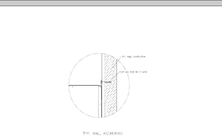
3.7.MOUNTING OF ENCLOSED TRANSFER SWITCHES
Model TS840, TS870 and TS880 Automatic Transfer Switches and Automatic Transfer and Bypass Isolation Switches in "standard" enclosures are seismic certified under AC156 building code for non-structural components.
"Standard" enclosures are all transfer switch enclosures Thomson Technology offers in NEMA 1, NEMA 2, NEMA 3R and NEMA 4X for the above listed product. If a customer requests a custom enclosure it would not be covered under the generic certificate; if certification were a requirement Consult factory before ordering.
The Automatic Transfer Switches are qualified to the highest known level in North America; based on site class D. Specifically this is a spectral acceleration of 342%. The transfer switch must be installed per the anchoring details provided for seismic qualification. The equipment can be mounted in alternate means and still qualify if a qualified Civil Engineer designs the alternate method of anchoring.
PM064 REV8 10/01/25 |
6 |
Thomson Technology |

TS 880 TRANSFER SWITCH
PM064 REV8 10/01/25 |
Thomson Technology |
TS 880 TRANSFER SWITCH
Anchoring Notes:
1.Anchoring must be designed according to IBC 2006 or latest version.
2.The anchoring details shown are recommended according to the seismic certification; design Engineer may use alternate anchors within the scope of IBC.
3.Wall anchors in concrete; use a typical concrete anchor as necessary.
4.Expansion anchors as shown. To be installed according to manufacturer's recommendation.
5.The 800-1200A NEMA 3R ATS enclosure may be floor/wall mounted or it may be free standing (floor mounted only); If free standing it must be a minimum of 12" (305mm) away from pipes, conduits or other obstructions to allow for sway during a seismic event.
.
PM064 REV8 10/01/25 |
8 |
Thomson Technology |

TS 880 TRANSFER SWITCH
4.GENERAL DESCRIPTION
Thomson Technology TS 880 series of Automatic Transfer Switches employ two mechanically interlocked enclosed contact power switching units and a microprocessor based controller to automatically transfer system load to a generator supply in the event of a utility supply failure. System load is then automatically re-transferred back to the utility supply following restoration of the utility power source to within normal operating limits.
The standard TS 880 series Automatic Transfer Switch is rated for 100% system load and requires upstream over current protection. The TS 880 Automatic Transfer Switch may be supplied with optional integral over current protection within the enclosed contact power switching units for applications such as Service Entrance Rated equipment. Refer to Section 6 of this manual for detailed information on over current protection.
The TS 880 series transfer switches employs a TSC 800 microprocessor based controller which provides all necessary control functions for fully automatic operation. The TSC 800 controller is mounted on the door of the transfer switch enclosure and operating status is shown via LED lights and LCD display module. For further information on the TSC 800 Transfer Controller, refer to instruction manual PM049.
100A-1200A rated molded case power switching devices used for the utility and generator sources are operated by an electrically driven motor mechanism in the transfer switch. 800A-4000A rated insulated case power switching devices used for the utility and generator sources are operated by internal drive motor operators. The transfer switch mechanism utilizes the power from the source to which the electrical load is being transferred. The mechanism provides a positive mechanical interlock to prevent both power switching units from being closed at the same time, which allows an interrupted open transition “break-before-make” transfer sequence. For transfer switches supplied with Closed Transition transfer option, the mechanical interlock is removed thereby allowing a “make-before break” transfer sequence when both sources of power are available. The TSC 800 transfer controller provides a standard neutral position delay timer for open transition transfer sequences to allow adequate voltage decay during transfer operation to prevent out of phase transfers.
Note: For the purpose of this manual, the following standard nomenclature is utilized:
qUtility: to indicate the source of primary power
qGenerator: to indicate the source of standby power
qPower switching device: to indicate the automatic transfer switch power switching device
PM064 REV8 10/01/25 |
9 |
Thomson Technology |

TS 880 TRANSFER SWITCH
4.1.PRODUCT MODEL CODE
The type of TS 880 series transfer switch supplied is identified by way of a 21 digit product code which appears on the equipment rating plate (MODEL) on the door of the transfer switch, and on the transfer switch drawings. The model code structure and definitions are as follows:
1 |
2 |
4 |
5 |
6 |
7 |
8 |
9 |
10 |
11 |
12 |
13 |
14 |
15 |
16 |
17 |
18 |
19 |
20 |
21 |
|
T |
S |
|
8 |
8 |
|
|
|
|
|
|
|
|
|
|
|
|
|
|
|
|
|
|
|
|
|
|
|
|
|
|
|
|
|
|
|
|
|
|
|
|
|
|
1-3. SERIES |
15 . VOLTAGE (CONTINUED) |
|
TS - TRANSFER SWITCH |
3f 4 WIRE (GROUNDED NEUTRAL) |
|
|
E - 120/208 1 |
|
4 & 5. MODEL |
F - 127/220 |
|
88 - 880 SWITCH |
G - 120240 1 (DELTA) |
|
|
H - 220/380 2 |
|
6. POLES |
J - 240/416 |
|
2 - 2 POLE |
K - 254/440 |
|
3 - 3 POLE |
M - 277/480 1 |
|
4 - 4 POLE |
N - 347/600 1 |
|
|
3f 3 WIRE |
|
7. CONFIGURATION TYPE |
P - 208 |
|
A - ATS |
Q - 220 |
|
B - BYPASS/ISOLATION ATS |
R - 240 |
|
X - SPECIAL |
S - 380 2 |
|
|
U - 416 |
|
8 - 11. AMPERAGE |
V - 480 |
0100 |
W - 600 |
|
0150 |
X - SPECIAL |
|
0200 |
|
|
0250 |
16. CONTROLLER |
|
0400 |
2 - TSC800 |
|
0600 |
7 - NONE (MANUAL) |
|
0800 |
|
|
1000 |
17. ENCLOSURE TYPE |
|
1200 |
A - NEMA1, ASA #61 GREY |
|
1600 |
B - NEMA2, ASA #61 GREY |
|
2000 |
C - NEMA12, ASA #61 GREY |
|
2500 |
D - NEMA3R SD, ASA #61 GREY |
|
3000 |
E - NEMA3R/4 DD, ASA #61 GREY 3 |
|
4000 |
F - NEMA3RX/4X DD |
|
|
|
(306 STAINLESS STEEL) 3 |
|
12. APPLICATION |
G - NONE (OPEN STYLE) |
|
A - STANDARD |
H - NEMA 3RXDD (ALUMINUM) |
|
B - SERVICE ENTRANCE |
ASA#61 GREY 4 |
|
C - DUAL SOURCE |
X - SPECIAL |
|
X - SPECIAL |
|
|
|
18. UTILITY SWITCHING DEVICE |
|
13. OPERATION TYPE |
K - MOLDED CASE SWITCH (100 - 1200 A) |
|
1 - OPEN TRANSITION |
M - MOLDED CASE SWITCH C/W THER-MAG |
|
2 - MANUAL ELEC. OP. |
TRIP (100-200A) |
|
3 - CLOSED TRANSITION (MOMENTARY) |
N - MOLDED CASE SWITCH C/W ELECTRONIC |
|
4 - CLOSED TRANSITION (SOFT LOAD) |
TRIP (250-1200A) |
|
X - SPECIAL |
P - MOLDED CASE SWITCH C/W ELECTRONIC |
|
|
& GF TRIP (250-1200A) |
|
14 . SAFETY STANDARD |
Q - INSULATED CASE, FIX MOUNT SWITCH |
|
A - UL 1008 |
(800A-4000A) |
|
B - CSA C22.2 NO 178 |
R - INSULATED CASE, FIX-MOUNT SWITCH |
|
X - NOT APPLICABLE |
C/W ELECTRONIC TRIP (800-4000A) |
|
|
T - INSULATED CASE, FIX-MOUNT SWITCH |
PM064 REV8 10/01/25 |
10 |
|
|
15 . VOLTAGE |
C/W ELECTRONIC & GF TRIP (800-4000A) |
|
1f 3 WIRE |
U - INSULATED CASE DRAW-OUT SWITCH |
|
D - 120/240 |
(800 - 4000A) |
18. UTILITY SWITCHING DEVICE (CONT'D)
V- INSULATED CASE DRAW-OUT SWITCH C/W ELECTRONIC TRIP (800 - 4000A)
W- INSULATED CASE, DRAW-OUT SWITCH C/W ELECTRONIC & GF TRIP (800-4000A)
X- SPECIAL
19.GENERATOR SWITCHING DEVICE
K- MOLDED CASE SWITCH (100 - 1200 A)
M- MOLDED CASE SWITCH C/W THER-MAG TRIP (100-200A)
N- MOLDED CASE SWITCH C/W ELECTRONIC TRIP (250-1200A)
P- MOLDED CASE SWITCH C/W ELECTRONIC
& GF TRIP (250-1200A)
Q - INSULATED CASE, FIX MOUNT SWITCH (800A-4000A)
R - INSULATED CASE, FIX-MOUNT SWITCH C/W ELECTRONIC TRIP (800-4000A)
T - INSULATED CASE, FIX-MOUNT SWITCH C/W ELECTRONIC & GF TRIP (800-4000A)
U- INSULATED CASE DRAW-OUT SWITCH (800 - 4000A)
V- INSULATED CASE DRAW-OUT SWITCH C/W ELECTRONIC TRIP (800 - 4000A)
W- INSULATED CASE, DRAW-OUT SWITCH C/W ELECTRONIC & GF TRIP (800-4000A)
X- SPECIAL
20.POWER CONNECTIONS
A- STANDARD
X - SPECIAL
21. ATS CONNECTION CONFIGURATION 5
A - STANDARD
B - ALTERNATE B (400-1200A)
C - ALTERNATE C (400-1200A)
D - ALTERNATE D (400-1200A)
E - ALTERNATE E (800-4000A)
F - ALTERNATE F (800-4000A)
G - ALTERNATE G (800-4000A)
X - SPECIAL
NOTES
1MULTI-VOLTAGE CAPABLE.
2FOR 50 Hz APPLICATION.
3STANDARD ENCLOSURE RATING IS N3R
AT 800A AND ABOVE AND N4 AT 600A AND BELOW.
4 ONLY AVAILABLE 800A AND ABOVE.
5 Thomson Technology
FOR BYPASS SWITCH APPLICATIONS
REFER TO FACTORY

TS 880 TRANSFER SWITCH
4.2.TYPICAL COMMISSIONING PROCEDURES
CAUTION!!!
Commissioning procedures must be performed by qualified personnel only. Ensure the Automatic Transfer Switch (ATS) Isolation Plug is disconnected prior to energizing the supply sources. Manually place the transfer switch mechanism in the neutral position prior to applying power. Failure to do so may result in equipment failure or personal injury.
Note: The TYPICAL AUTOMATIC TRANSFER SWITCH COMMISSIONING
PROCEDURES MODEL SERIES TS 880 (attached as “APPENDIX A”) is provided for general information only pertaining to typical site installations and applications. Contact Thomson Technology for further information as may be required.
5.GENERAL THEORY OF OPERATION
5.1. STANDARD AUTOMATIC TRANSFER SWITCH
5.1.1. NORMAL SEQUENCE OF OPERATION - OPEN TRANSITION
TYPE TRANSFER SWITCHES
When utility supply voltage drops below a preset nominal value (adjustable from 70% to 99% of nominal) on any phase, an engine start delay circuit is initiated and the transfer to utility supply signal will be removed (i.e. contact opening). Following expiry of the engine start delay period (adjustable from 0 to 60 sec.) an engine start signal (contact closure) will be given.
Once the engine starts, the transfer switch controller will monitor the generator voltage and frequency. Once the generator voltage and frequency rises above preset values (adjustable from 70% to 99% of nominal), the engine warmup timer will be initiated. Once the warmup timer expires (adjustable from 0 to 60 min.), the transfer to Generator Supply signal (contact closure) will be given to the transfer switch mechanism. The load will then transfer from the utility supply to the generator supply via the motor operated mechanism. Note: A neutral delay timer circuit will delay the transfer sequence in the neutral position (i.e. both power-switching devices open) until the selected time expires (adjustable from 0 to 60 sec.).
PM064 REV8 10/01/25 |
11 |
Thomson Technology |

TS 880 TRANSFER SWITCH
The generator will continue to supply the load until the utility supply has returned. The retransfer sequence is completed as follows: when the utility supply voltage is restored to above the preset values (adjustable from 70% to 99% of nominal) on all phases, a utility return delay circuit will be initiated. Following expiry of the Utility Return Timer (adjustable from 0 to 60 min.), the Transfer to Generator Supply signal will be removed (contact opening), and then the Transfer to Utility Supply signal (contact closure) will be given to the transfer switch mechanism. The load will then retransfer the load from the generator supply back to the utility supply. Note: A neutral delay timer circuit will delay the transfer sequence in the neutral position (i.e. both power switching devices open) until the neutral delay time period expires (adjustable from 0 to 60 seconds).
An engine cooldown timer circuit will be initiated once the load is transferred from the generator supply. Following expiry of the cooldown delay period (adjustable from 0 to 30 minutes), the engine start signal will be removed (contact opening) to initiate stopping of the generator set.
5.1.2. NORMAL SEQUENCE OF OPERATION - CLOSED TRANSITION
TYPE TRANSFER SWITCH OPTION
For transfer switches equipped with the Closed Transition transfer option, the ATS is configured to operate as follows:
Under normal closed transition operating conditions, the transfer switch operates automatically during a failure and restoration of utility power and does not require operator intervention.
When utility supply voltage drops below a preset nominal value (70 - 99% of rated adjustable) on any phase, an engine start delay circuit will be initiated and the transfer to utility supply signal will be removed (i.e. contact opening). Following expiry of the engine start delay period (0 - 60 sec. adjustable) an engine start signal (contact closure) will be given.
Once the engine starts, the transfer switch controller will monitor the generators voltage and frequency levels. Once the generator voltage and frequency rises above preset values (70 – 99% nominal adjustable) a warmup time delay will be initiated. Once the warmup timer (0-60 Min adjustable) expires, the transfer to
PM064 REV8 10/01/25 |
12 |
Thomson Technology |
TS 880 TRANSFER SWITCH
generator supply signal (contact closure) will be given to the transfer switch mechanism. The load will then transfer from the utility supply (i.e. opening the utility power switching device) to the generator supply (closing the generator power switching device) via motor driven mechanism to complete a “break-before-make” open transition transfer sequence.
The generator will continue to supply the load until the utility supply has returned and the retransfer sequence is completed as follows: When the utility supply voltage is restored to above the present values (70 - 99% of rated adjustable) on all phases, a re-transfer sequence will be initiated once the Utility Return timer expires. The utility will close its power switching device when it is in synchronism with the generator supply via external logic device. The generator power switching device will immediately trip open approximately 50-100 milliseconds after the utility power switching device closes to complete the “make-before-break” re-transfer sequence.
An engine cooldown timer circuit will be initiated once the load is transferred from the generator supply. Following expiry of the cooldown delay period (0 - 60 min. adjustable) the engine start signal will be removed (contact opening) to initiate stopping of the generator set.
PM064 REV8 10/01/25 |
13 |
Thomson Technology |

TS 880 TRANSFER SWITCH
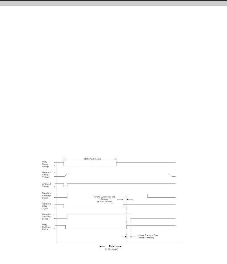
Closed Transition Operation Sequence Diagram
(Normal Power Failure & Return Sequence)
The following operating sequences and time delays are associated with closed transition type transfer switches which momentarily parallel two sources of supply for less than 100 milliseconds. For closed transition type transfer switches, which utilize extended parallel operation for soft-loading operating sequences, refer to separate instruction manual.
1.Transfer Control Switch (Open/Closed Transition): A two position selector switch is provided on the front of the transfer switch for operator section of desired operation. The 2 positions are as follows:
§OPEN TRANSITION: The transfer switch will operate in a “break- before-make” open transition sequence during load transfers. A programmed neutral delay period will occur during the transfer sequence to ensure voltage decays on the load bus before load is re-applied. The two sources will not be paralleled at any time during operation in this mode.
§CLOSED TRANSITION: When both sources of supply are available, the transfer switch will operate in a “make-before-break” closed transition sequence during load transfers. Note: If only one source of supply is available during an initiated transfer sequence, the control system will automatically revert to an open transition transfer sequence.
2.Synchronizing Protection: To ensure both sources are in synchronism prior to initiating a closed transition transfer sequence, a sync check relay is used (Device 25). The synch check relay is door mounted and proved a LED light Synchroscope to monitor phase angle of the two sources. The synch check relay will block a closed transition transfer sequence until both sources phase angle and voltages are within programmed limits. The synch check relay settings are field programmable (+-5 to 20 Deg Phase Angle (rw) and 1-10% voltage difference (rU) and they must be set at time of final equipment commissioning for desired values. The factory settings are as follows:
PM064 REV8 10/01/25 |
14 |
Thomson Technology |
TS 880 TRANSFER SWITCH
Note: The standard closed transition transfer switch does not contain an automatic synchronizer to control the generators frequency or voltage to bring it within limits of the sync check relay. For correct closed transition transfer operation, the system requires the generators frequency to be set within 0.25% of nominal frequency and the generators voltage to be set within 0.5% of nominal voltage.
3.Closed Transition Time Period: The time period in which both sources of supply are paralleled together during the closed transition transfer sequence is 50-100 milliseconds (maximum). The time period is inherently controlled by operation of auxiliary contacts from the power switching devices (i.e. when one switching devices closes, its aux contact closes to initiate tripping of the opposite switching device).
4.Closed Transition Failure Mode Operation: A control logic circuit and timer (CFT) continually monitors the closed transition operation time period. The CFT timer is factory set for 100 milliseconds that allows normal closed transition operation (i.e. both power switching devices remain closed for less than 100 milliseconds). The timer and alarm circuit is not activated under normal operation. Should the closed transition operation time exceed 100 milliseconds (i.e. both power switching devices remain closed for longer than the normal closed transition time period plus the setting of timer CFT), the following sequence of events will occur: q CFT time delay period will expire and will activate auxiliary trip relay.
qIf the transfer switch was transferring power from the generator source to the utility source and the generator switching device failed to open, an auxiliary
trip relay will trip open the utility power switching device to immediately separate the two power sources. If the transfer switch was transferring power from the utility source to the generator source and the utility switching device failed to open, an auxiliary trip relay will trip open the generator power switching device to immediately separate the two power sources.
PM064 REV8 10/01/25 |
15 |
Thomson Technology |
 Loading...