


TSC 80e
TRANSFER SWITCH CONTROLLER
INSTALLATION, OPERATING &
SERVICE MANUAL
Software Version 2.2
PM091 Rev 1 09/02/27
9087A – 198th Street, Langley, BC Canada V1M 3B1 Telephone (604) 888-0110 Telefax (604) 888-3381 E-Mail: info@thomsontechnology.com www.thomsontechnology.com

TSC 80e TRANSFER SWITCH CONTROLLER
|
TABLE OF CONTENTS |
|
1. |
INTRODUCTION |
1 |
|
1.1. PRODUCT REVISION HISTORY |
1 |
|
1.2. GENERAL INFORMATION |
2 |
|
1.3. NOTES TO TRANSFER SWITCH INSTALLER |
2 |
|
1.3.1. SYSTEM VOLTAGE |
2 |
|
1.3.2. SYSTEM PHASING - HIGH LEG DELTA SYSTEMS |
3 |
|
1.3.3. REMOTE START CONTACT FIELD WIRING |
4 |
|
1.3.4. DIELECTRIC TESTING |
4 |
2. |
DESCRIPTION |
5 |
|
2.1. LEXAN FACEPLATE |
5 |
|
2.2. PRINTED CIRCUIT BOARD |
7 |
|
2.2.1. TERMINAL BLOCKS |
8 |
|
2.2.2. DIAGNOSTIC LED’S |
8 |
|
2.3. TSC 80e CONTROLLER FEATURES |
9 |
|
2.4. APPLICATION INFORMATION |
11 |
|
2.4.1. AC VOLTAGE SENSING INPUT |
11 |
|
2.4.2. AC CONTROL POWER INPUT |
13 |
|
2.4.3. OUTPUTS |
13 |
3. |
OPERATING INSTRUCTIONS |
14 |
|
3.1. AUTOMATIC SEQUENCE OF OPERATION |
14 |
|
3.1.1. NORMAL OPERATION |
14 |
|
3.1.2. ABNORMAL OPERATION |
15 |
|
3.2. TEST MODES |
17 |
|
3.2.1. UTILITY POWER FAIL SIMULATION (LOAD TEST) |
17 |
|
3.2.2. AUTOMATIC PLANT EXERCISE TEST |
18 |
|
3.2.3. FOUR FUNCTION REMOTE TEST (FTS4 OPTION) |
19 |
|
3.2.4. REMOTE TEST |
20 |
|
3.3. TRANSFER FAIL FAULT RESET |
20 |
|
3.4. LAMP TEST |
21 |
|
3.5. TIMER BYPASS |
21 |
|
3.6. TSC 80e LCD DISPLAY OPERATION |
22 |
|
3.6.1. LCD DISPLAY SCREENS |
22 |
|
3.6.2. LCD DISPLAY MODE OPERATION |
25 |
|
3.6.3. SYSTEM STATISTICS |
25 |
PM091 Rev 1 09/02/27 |
Thomson Technology |

TSC 80e TRANSFER SWITCH CONTROLLER
|
3.6.4. DATALOG MENU |
26 |
4. |
TSC 80E SOFTWARE PROGRAMMING INSTRUCTIONS |
27 |
4.1. PASSWORDS |
27 |
|
|
4.1.1. USER READ (VIEW ONLY MODE) |
27 |
|
4.1.2. USER READ / WRITE MODE |
27 |
|
4.1.3. MASTER READ / WRITE MODE |
27 |
|
4.1.4. PASSWORD ENTRY PROCEDURE |
28 |
4.2. SOFTWARE PROGRAMMING PROCEDURE |
28 |
|
4.3. PROGRAMMING DISPLAY MAIN MENU SCREENS |
30 |
|
4.4. QUICK GUIDE VOLTAGE CHANGE PROGRAMMING PROCEDURE |
31 |
|
4.5. QUICK GUIDE PROGRAMMABLE OUTPUTS PROGRAMMING PROCEDURE |
32 |
|
4.6. PROGRAMMING DISPLAY SUB-MENU DESCRIPTIONS |
33 |
|
|
4.6.1. PASSWORD ENTRY & RESET |
33 |
|
4.6.2. SYSTEM DATE & TIME |
34 |
|
4.6.3. AUTO EXERCISE TIMER |
34 |
|
4.6.4. SYSTEM OPTIONS |
36 |
|
4.6.5. SYSTEM CONFIG |
36 |
|
4.6.6. VOLTAGE CALIBRATION |
41 |
|
4.6.7. UTILITY VOLTAGE SETPOINTS |
44 |
|
4.6.8. GENERATOR VOLTAGE & FREQUENCY SETPOINTS |
45 |
|
4.6.9. SYSTEM TIMING DELAYS |
45 |
|
4.6.10. PROGRAMMABLE OUTPUTS |
47 |
|
4.6.11. SYSTEM STATISTICS |
50 |
|
4.6.12. DATALOGS |
51 |
4.7. TSC 80e FACTORY DEFAULT PROGRAMMING SETTINGS |
52 |
|
5. |
TSC 80E TYPICAL CONNECTION DIAGRAM |
53 |
6. |
TSC 80E SPECIFICATIONS |
54 |
7. |
TROUBLESHOOTING |
55 |
8. |
TSC 80E REPLACEMENT PARTS |
56 |
9. |
PRODUCT RETURN POLICY |
57 |
10. |
NOTES |
58 |
PM091 Rev 1 09/02/27 |
Thomson Technology |
TSC 80e TRANSFER SWITCH CONTROLLER
1.INTRODUCTION
1.1.PRODUCT REVISION HISTORY
The following information provides an historical summary of changes made to this product
since the original release.
Software Version
2.2 09/02/27 |
Software revised for TSC 80 Controllers. No changes to TSC 80e |
|
Controller features or operation. |
|
|
2.1 09/01/21 |
Software updated to incorporate Configurable PT Ratio for 3 phase, |
|
3 wire applications |
|
|
2.0 08/08/14 |
Original software release for TSC 80e |
|
|
|
|
Operating & Service Manual Version
Rev 0 09/01/19 Original release of dedicated Manual for TSC 80e
Contact Thomson Technology, to obtain applicable instruction manuals. Soft copy of most current version is available at www.thomsontechnology.com.
PM091 Rev 1 09/02/27 |
1 |
Thomson Technology |
TSC 80e TRANSFER SWITCH CONTROLLER
1.2.GENERAL INFORMATION
NOTE:
Installations should be done in accordance with all applicable electrical regulation codes as required.
The following information is provided for general information only pertaining to TSC 80e Transfer Switch Controllers installed in a Thomson Technology Automatic Transfer Switch as applied in a typical site installation. For specific site installation information, consult Thomson Technology as required.
CAUTION
contents subject to damage by
STATIC ELECTRICITY
This equipment contains static-sensitive parts. Please observe the following anti-static precautions at all times when handling this equipment. Failure to observe these precautions may cause equipment failure and/or damage.
•Discharge body static charge before handling the equipment (contact a grounded surface and maintain contact while handling the equipment, a grounded wrist strap can/should also be utilized).
•Do not touch any components on the printed circuit board with your hands or any other conductive equipment.
•Do not place the equipment on or near materials such as Styrofoam, plastic and vinyl. Place the equipment on grounded surfaces and only use an anti-static bag for transporting the equipment.
1.3.NOTES TO TRANSFER SWITCH INSTALLER
1.3.1. SYSTEM VOLTAGE
If the transfer switch has programmable/multi-tap system voltage capability (refer to electrical schematic), confirm the transfer switch has been configured for the correct
PM091 Rev 1 09/02/27 |
2 |
Thomson Technology |
TSC 80e TRANSFER SWITCH CONTROLLER
system voltage. If the transfer switch requires reconfiguring, the TSC80e controller will require re-programming as well.
WARNING
Failure to confirm and match transfer switch voltage with the system voltage could cause serious equipment damage.
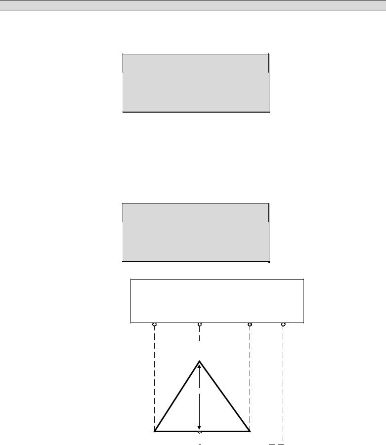
1.3.2. SYSTEM PHASING - HIGH LEG DELTA SYSTEMS
When the transfer switch is connected to a 3-phase 4-wire delta systems, the “High” leg (Phase B, colored Orange), must be connected to Phase B of the Utility and/or Generator supply. This will ensure the ATS control power, which is internally connected between Phase A and Neutral is maintained at 120VAC. Refer to figure below for further details.
WARNING
Failure to match correct system phasing
will result in serious damage to the
TSC 80e controller.
Automatic Transfer
Switch (Utility Supply)
PH A |
PH B |
PH C |
Neural |
(UA) |
(UB) |
(UC) |
(N) |
B
(Orange)
(High Leg)
240V |
208V |
240V |
A |
120V |
|
|
|
|
120V |
|
|
|
|
|
C |
||||
|
||||||||||||||||
(R ed) |
|
|
|
|
|
|
|
|
|
|
|
|
|
(Yellow) |
||
|
|
|
|
|
|
|
|
|
|
|
|
|
||||
|
|
|
|
|
|
|
|
|
|
|
|
|
|
|
|
|
N
(W hite)
PM091 Rev 1 09/02/27 |
3 |
Thomson Technology |
TSC 80e TRANSFER SWITCH CONTROLLER
CAUTION!!!
All installation and/or service work performed must be done by qualified personnel only. Failure to do so may cause personal injury or death.
1.3.3. REMOTE START CONTACT FIELD WIRING
As a minimum, the remote engine start control field wiring shall conform to the local
regulatory authority on electrical installations. Field wiring of a remote start contact
from a transfer switch to a control panel should conform to the following guidelines to
avoid possible controller malfunction and/or damage.
1.3.3.1.Minimum #14 AWG (2.5mm2) wire size shall be used for distances up to 100ft (30m)1). For distances exceeding 100 ft. (30m) consult Thomson Technology.
1.3.3.2.Remote start contact wires should be run in a separate conduit.
1.3.3.3.Avoid wiring near AC power cables to prevent pick-up of induced voltages.
1.3.3.4.An interposing relay may be required if field-wiring distance is excessively long (i.e. greater than 100 feet (30m)) and/or if a remote contact has a resistance of greater than 5.0 ohms.
1.3.3.5.The remote start contact provided is voltage free (i.e. dry contact). Refer to the “TSC 80e Typical Connection Diagram” on page 52 for terminal interface and contact voltage/current ratings or page 13 for specifications on output contact ratings. Applying voltage or current in excess of the ratings will damage the controller and is not cover by Thomson Technology’s limited warranty.
1.3.4. DIELECTRIC TESTING
Do not perform any high voltage dielectric testing on the transfer switch with the
TSC80e controller connected into the circuit, as serious damage will occur to the
controller. All AC control fuses and control circuit isolation plugs connected to the
TSC80e must be removed if high voltage dielectric testing is performed on the transfer
switch.
PM091 Rev 1 09/02/27 |
4 |
Thomson Technology |

TSC 80e TRANSFER SWITCH CONTROLLER
2.DESCRIPTION
The TSC 80e controller utilizes microprocessor-based design technology, which provides high accuracy for all voltage sensing and timing functions. The TSC 80e is factory configured to control all the operational functions and display features of the automatic transfer switch.
The TSC 80e controller consists of two parts; a Lexan faceplate, which is mounted externally on the transfer switch door, and a printed circuit board (PCB), which is mounted inside the transfer switch on the enclosure door. The TSC 80e PCB contains a built-in LCD display that is visible from the front panel faceplate. The Lexan faceplate contains operation/data-acquisition/programming pushbuttons and indication LEDs.
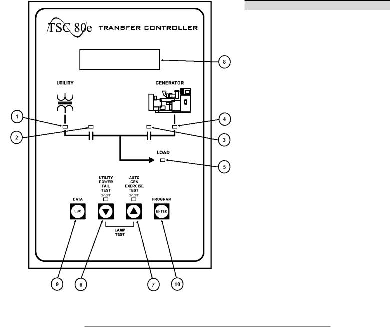
2.1.LEXAN FACEPLATE
The TSC 80e Controller Lexan faceplate is shown as in FIGURE 1. The Lexan pushbuttons and LED lights are connected to the main PCB via plug-in ribbon cable. The main features of the Lexan faceplate are described as follows with reference to FIGURE 1.
Utility Supply Available LED light
Load on Utility supply LED light
Load on Generator supply LED light
Generator Supply Available LED light
ATS Load Bus Energized LED light
Utility Power Fail Test Mode Pushbutton (Program value DECREMENT/DOWN Pushbutton) & LED light
Auto Generator Exercise Mode Pushbutton (Program value INCREMENT/UP Pushbutton) & LED light
LCD Display Screen Viewing Window
Programming Escape/Data Log review Pushbutton
Programming Enter Pushbutton
PM091 Rev 1 09/02/27 |
5 |
Thomson Technology |
TSC 80e TRANSFER SWITCH CONTROLLER
FIGURE 1 - TSC 80e Controller Lexan Faceplate
•ESC pushbutton. The ESC function is used to “ESCAPE” or exit the last field or programming menu. The program menu is a drill down format; by pressing the ESC button the program steps back one layer at a time until it escapes/exits the program menu. The ESC function can also be used to view the controllers Data Logs that are stored.
•DOWN pushbutton. The DOWN function is used to change or decrement values while in the programming mode and is used to scroll down through the status menus or programming sub menus to the next item.
PM091 Rev 1 09/02/27 |
6 |
Thomson Technology |
TSC 80e TRANSFER SWITCH CONTROLLER
•UP pushbutton. The UP function is used to change or increment a programming value while in the programming mode and is used to scroll up through the status menus or programming sub menus to the previous item.
•ENTER pushbutton. The ENTER function is used to access the Program menus and “enters” and accept new programming or operating mode changes after a new value has been selected.
2.2.PRINTED CIRCUIT BOARD
38 |
|
|
|
|
|
|
|
|
|
|
37 |
|
|
|
|
|
|
|
|
PROG 2 |
|
|
|
|
|
|
|
|
|
|
|
PROG 3 |
|
|
|
|
|
|
|
|
|
|
|
PROG 1 |
|
|
|
44 |
TB7 |
|
|
|
|
|
|
|
|
TB6 |
29 |
|
|
|
|
|
|
|
|
|
|
|
|
|
|
|
|
|
|
|
|
ENG STOP |
|
28 |
|
|
|
|
|
|
|
|
|
|
|
|
1 |
|
|
|
|
|
|
|
|
TRANSFORMER |
|
|
|
BT1 |
|
|
|
|
|
|
TRANSFORMER |
|
|
||
|
|
|
|
|
|
|
|
|
|
||
|
REAL TIME |
|
|
|
|
|
|
XFER UTIL |
|
|
|
|
|
|
|
|
SYS OK |
|
|
|
|
|
|
|
CLOCK |
|
|
|
|
|
|
|
|
|
|
|
|
|
|
|
|
|
|
|
|
|
|
|
BATTERY |
|
|
|
|
|
|
XFER GEN |
|
|
|
|
|
|
|
|
|
|
|
LD ON GEN |
|
|
|
|
|
|
|
|
|
|
|
(PROG 4) |
|
|
|
|
|
|
|
|
|
|
|
LD ON UTIL |
|
|
|
|
|
|
|
|
|
|
|
(PROG 5) |
|
|
|
|
|
|
|
|
|
|
|
|
|
|
11 |
|
|
|
|
|
|
|
|
|
|
|
TB2-5 |
|
1 |
2 |
3 |
4 |
5 |
6 |
7 |
8 |
9 |
10 |
|
TB1 |
|
|
|
|
|
|
|
|
|
|
|
FIGURE 2
The printed circuit board (PCB) is shown in FIGURE 2. The PCB contains the following user
interface items:
PM091 Rev 1 09/02/27 |
7 |
Thomson Technology |

TSC 80e TRANSFER SWITCH CONTROLLER
2.2.1. TERMINAL BLOCKS
Terminal blocks are located on the PCB as follows:
TB1 High voltage sensing terminal block (120-600VAC).
WARNING
Voltage sensing circuits are capable of lethal voltages while energized. Standard safety procedures should be followed and be performed by qualified personnel only. Failure to do so may cause personnel injury and/or death.
TB2-TB6 Transfer control terminal block for 120VAC control power and input/output circuits.
TB7 Low voltage control inputs (5VDC internally powered, switched to terminal 38).
2.2.2. DIAGNOSTIC LED’S
The TSC 80e controller provides diagnostic LED lights, which are mounted on the printed circuit board as per FIGURE 2. Their functions are described as follows:
SYS OK |
LED flashes on and off at irregular intervals, which indicates |
|
the microprocessor is functioning normally. |
XFER TO UTILITY |
LED illuminates whenever the TSC 80e is initiating a signal |
|
to transfer to the Utility supply. (UP transfer contact as noted |
|
on the electrical schematic is closed) |
XFER TO GEN |
LED illuminates whenever the TSC 80e is initiating a signal |
|
to transfer to the Generator supply. (GP transfer contact as |
|
noted on the electrical schematic is closed) |
ENG STOP |
LED illuminates whenever the TSC 80e is initiating an |
|
ENGINE STOP (remote start contact is open). |
PROG 1 |
LED illuminates whenever the Programmable output Relay |
|
#1 is turned on (relay on the circuit board is energized). |
PROG 2 |
LED illuminates whenever the Programmable output Relay |
|
#2 is turned on (relay on the circuit board is energized). |
PROG 3 |
LED illuminates whenever the Programmable output Relay |
|
#3 is turned on (relay on the circuit board is energized). |
PM091 Rev 1 09/02/27 |
8 |
Thomson Technology |

TSC 80e TRANSFER SWITCH CONTROLLER
LD ON GEN (PROG 4) LED illuminates whenever the Programmable output Relay #4 is turned on (relay on the circuit board is energized). Factory default function is “Load on Gen”.
LD ON UTIL (PROG 5) LED illuminates whenever the Programmable output Relay #5 is turned on (relay on the circuit board is energized). Factory default function is “Load on Utility”.
2.3.TSC 80e CONTROLLER FEATURES
The Thomson Technology TSC 80e Transfer Switch Controller utilizes the latest advancements in microprocessor technology, printed circuit board assembly and software for control of automatic transfer switches. The TSC 80e is the second generation of microprocessor-based transfer switch controllers from Thomson Technology, and reflects over 30 years of transfer switch control experience. The TSC 80e is factory configured to monitor, display and control all operational functions of the automatic transfer switch. All voltage sensors and timers are fully user adjustable utilizing software configuration. The microprocessor design provides high accuracy for all voltage sensing and timing functions as well as providing many standard features.
•Utility AC voltage sensing (true RMS) – 120-600V single phase or 3 phase
•Generator AC voltage sensing (true RMS) – 120-600V single phase or 3 phase
•Generator AC frequency sensing
•Utility under voltage control setpoint 70 - 95% (adjustable)
•Generator under voltage control setpoint 70 - 95% (adjustable)
•Generator under frequency control setpoint 70 - 90% (adjustable)
•Engine warm-up timer 0-60 sec. (adjustable)
•Utility return timer 0-30 min. (adjustable)
•Engine start timer 0-60 sec. (adjustable)
•Engine cooldown timer 0-30 min. (adjustable)
•Neutral position delay timer 0-60 sec. (adjustable)
•Local utility power fail simulation test pushbutton & LED, door mounted
•Remote utility power fail simulation test pushbutton input (via terminal block)
•Load on utility supply & load on generator supply LED’s, door mounted
•Utility and generator source available LED’s, door mounted
•Weekly plant exercise timer (30 min. on load) manually initiated
PM091 Rev 1 09/02/27 |
9 |
Thomson Technology |

TSC 80e TRANSFER SWITCH CONTROLLER
•Local plant exercise initiate pushbutton & LED, door mounted
•Engine start contact (10A, 120/240VAC resistive max.)
•Transfer fail/forced transfer logic
•Automatic force transfer to alternate supply should load voltage become deenergized
•50 or 60Hz capable (120V control power)
•Remote Load Test/Peak Shave Input
•LCD Display: Built-in, front faceplate mounted LCD Display for monitoring 3 phase Utility/Generator voltage, system frequency and timer countdown operation
•Front Panel Programming: All controller set points can be programmed using built-in faceplate mounted pushbuttons & LCD display with password security
•Load Disconnect Contact (LDC): Integrated Load Disconnect Contact (LDC) feature provides pre/post transfer control to signal external building systems such as elevators during transfer operations
•Generator Exercise Timer (EXT): Integrated Generator Exercise Timer (EXT) with easy to use 4 event, 7-14-21-28 Day, On-load or Off-load Programmability
•Real-time Clock: On Board Real-time clock c/w battery back-up & daylightsavings programming functionality
•Event Data Logging: Data logging of key events including total transfers to generator, total utility power failures, load on utility hours, load on generator hours and utility or generator voltage/ frequency data at time of fault
•5 Programmable Output Contacts: Additional Programmable Output Contact rated 10A, 120/240V resistive, Form C with the following available functions: Fail to Transfer, Load on Utility, Load on Gen, Utility Power Available (UPA), Generator Power Available (GPA), ATS Not in Auto, ATS in Auto, Transfer to Gen, Transfer to utility, Switch failure, and limit switch failure.
PM091 Rev 1 09/02/27 |
10 |
Thomson Technology |

TSC 80e TRANSFER SWITCH CONTROLLER
2.4.APPLICATION INFORMATION
2.4.1. AC VOLTAGE SENSING INPUT
The TSC 80e can accept direct AC voltage sensing inputs on the generator and utility supplies from 120-600VAC (nominal). Note: Direct input voltage sensing can only be used when the system utilizes a 3 phase, 4 wire distribution system which has the neutral conductor solidly grounded. For 3 phase, 3 wire systems (i.e. no neutral) or high voltage systems, potential transformers must be used. Refer to FIGURE 3 for voltage sensing connections.
PM091 Rev 1 09/02/27 |
11 |
Thomson Technology |

TSC 80e TRANSFER SWITCH CONTROLLER
3Ø, 4W 208/380/480/600VAC DIRECT SENSING |
SINGLE PHASE, 3W 120/240VAC DIRECT SENSING |
||||||||
TSC 80e |
|
|
A |
B |
C |
N |
TSC 80e |
L1 L2 |
N |
|
|
|
|
|
|
GRD |
|
|
GRD |
1 |
|
|
|
|
|
|
1 |
|
|
2 |
|
|
|
|
|
|
2 |
|
|
3 |
|
|
|
|
|
|
3 |
|
|
|
|
|
|
|
|
|
NO CONNECTION |
|
|
25 |
|
1 |
|
|
|
|
10 |
|
|
|
|
|
|
|
|
|
|
||
26 |
120 |
|
|
|
|
|
25 |
|
|
|
|
|
|
|
|
|
|
||
24 |
GRD |
|
|
|
|
|
26 |
|
|
|
|
|
|
|
|
|
|
||
|
GRD |
|
|
|
|
|
24 |
|
|
|
|
|
|
|
|
|
|
|
|
|
|
|
|
|
|
|
GRD |
|
|
VOLTAGE INPUTS |
|
|
|
|
|
|
|
|
|
600VAC L-L, 347VAC L-N |
|
|
|
|
|
|
|
||
480VAC L-L, 277VAC L-N |
|
|
|
|
|
|
|
||
380VAC L-L, 220VAC L-N |
|
|
|
|
VOLTAGE INPUTS |
|
|
||
208VAC L-L, 120VAC L-N |
|
|
|
|
240VAC L-L, 120VAC L-N |
|
|
||
|
|
|
|
|
|
|
|
|
|
1 |
PT REQUIRED FOR TRANSFER SWITCH MECHANISM POWER |
NOTE: UTILITY VOLTAGE SENSING SHOWN ONLY. |
|
(MUST BE SIZED TO SUIT POWER REQUIREMENTS). |
|||
|
|
||
|
NOTE: UTILITY VOLTAGE SENSING AND |
|
|
|
CONTROL POWER SHOWN ONLY. |
|
|
|
|
||
3Ø, 4W 120/240V HIGH LEG DELTA DIRECT CONNECTION |
3Ø, 3W DELTA PT's |
||
TSC 80e |
A |
B |
C |
N |
TSC 80e |
|
A |
B |
C |
|||
|
|
|
|
|
|
|||||||
|
|
|
|
|
GRD |
|
|
|
|
|
|
|
|
1 |
|
|
|
|
|
|
1 |
|
|
|
|
|
2 |
|
|
|
|
|
|
2 |
120 |
|
|
|
|
|
|
|
|
|
|
|
|
|
|
||
|
3 |
|
|
|
|
|
|
3 |
120 |
GRD |
|
|
|
|
|
|
|
|
|
|
|
|
|
||
|
25 |
|
|
|
|
|
2 |
25 |
|
1 |
|
|
|
26 |
120V |
|
|
|
|
|
26 |
120 |
|
|
|
|
|
|
|
|
|
|
|
|
|
|||
|
|
|
|
|
|
|
|
|
|
|
||
|
24 |
|
|
|
|
|
|
24 |
GRD |
|
|
|
|
|
|
|
|
|
|
|
|
|
|
||
|
|
GRD |
|
|
|
|
|
|
GRD |
|
|
|
|
|
A |
|
|
|
|
|
|
|
|
|
|
|
|
|
N |
|
|
|
|
|
SECONDARY PT VOLTAGE |
|
||
|
|
|
|
|
|
|
|
120VAC L-L [NO NEUTRAL] |
|
|||
|
|
|
|
|
|
|
|
|
|
|||
|
|
|
|
|
|
|
|
|
NOTE: ØB IS GROUNDED |
|
||
|
B |
|
C |
|
|
1 |
PT REQUIRED FOR TRANSFER SWITCH MECHANISM POWER |
|||||
|
|
|
|
|
|
|
|
(MUST BE SIZED TO SUIT POWER REQUIREMENTS). |
||||
NOTE: |
FOR HIGH LEG DELTA SYSTEMS PHASING OF CUSTOMER SUPPLY MUST |
|
|
TSC80e CONTROLLER MUST BE PROGRAMMED FOR CORRECT |
||||||||
BE CONNECTED AS SHOWN ABOVE. FAILURE TO COMPLY WILL RESULT IN DAMAGE |
2 |
|
||||||||||
|
PT RATIO AND SECONDARY PT VOLTAGE IN SOFTWARE |
|||||||||||
TO CONTROLLER. |
|
|
|
|
|
|
||||||
|
|
|
|
|
|
|
|
|
|
|
||
NOTE: UTILITY VOLTAGE SENSING AND CONTROL POWER SHOWN ONLY. |
NOTE: UTILITY VOLTAGE SENSING SHOWN ONLY. |
|
FIGURE 3
PM091 Rev 1 09/02/27 |
12 |
Thomson Technology |

TSC 80e TRANSFER SWITCH CONTROLLER
2.4.2. AC CONTROL POWER INPUT
The TSC 80e is factory supplied for 120VAC (nominal) control power input voltage. Independent AC control power is required from both utility and generator supplies. AC control power is utilized for internal TSC 80e control circuits and external control device loads. The TSC 80e requires approximately 6 VA power for internal control circuits. The maximum external load is limited by output contact ratings (i.e. 10A resistive, 120VAC). Total AC control power requirements for each supply must be determined by adding both internal and external load requirements.
2.4.3. OUTPUTS
The TSC 80e provides the following types of output circuits:
Engine Start Contact |
Isolated Form B contact (10A, 120VAC Resistive) |
Transfer to Utility Output |
120VAC, 10A (Resistive) powered output contact |
Transfer to Generator Output |
120VAC, 10A (Resistive) powered output contact |
The TSC 80e provides the following additional output circuits: |
|
Programmable Output |
Isolated Form C contact (10A, 120VAC/250VAC |
Contact #1 |
Resistive) |
Programmable Output |
Isolated Form C contact (10A, 120VAC/250VAC |
Contact #2 |
Resistive) |
Programmable Output |
Isolated Form C contact (10A, 120VAC/250VAC |
Contact #3 |
Resistive) |
Programmable Output |
Isolated Form C contact (10A, 120VAC/250VAC |
Contact #4 |
Resistive) |
Programmable Output |
Isolated Form C contact (10A, 120VAC/250VAC |
Contact #5 |
Resistive) |
Interposing relays are required between the TSC 80e outputs and the end device if loads exceed the output current rating.
PM091 Rev 1 09/02/27 |
13 |
Thomson Technology |

TSC 80e TRANSFER SWITCH CONTROLLER
3.OPERATING INSTRUCTIONS
To operate the TSC 80e controller and associated transfer switch using the front faceplate pushbuttons, refer to the following detailed operating instruction sub-section descriptions.
3.1.AUTOMATIC SEQUENCE OF OPERATION
3.1.1. NORMAL OPERATION
Under normal operating conditions, the transfer switch operates automatically during a failure and restoration of utility power and does not require operator intervention.
When utility supply voltage drops below a preset nominal value (70 - 95% of rated adjustable) on any one phase, an engine start delay will be initiated and the transfer to utility supply signal will be removed (i.e. contact opening). Following expiry of the engine start delay period (0 - 60 sec. adjustable) an engine start signal will be given (contact closure, relay drops out to initiate start sequence).
Once the engine starts, the transfer switch controller will monitor the generators voltage and frequency levels. When the generator voltage and frequency rises above preset values (70 - 95% nominal adjustable) the Engine Warm-up timer will be initiated. After the Engine Warm-up timer expires (0-60 sec. Adjustable), the transfer to generator supply signal (contact closure) will be given to the transfer switch mechanism. The load will then transfer from the utility supply to the generator supply via motor driven mechanism (Neutral Delay is bypassed on utility failure detection).
The generator will continue to supply the load until the utility supply has returned and the retransfer sequence is completed as follows: When the utility supply voltage is restored to above the present values (70 - 95% of rated adjustable) on all phases, a transfer return delay circuit will be initiated. Following expiry of the utility transfer return timer (0 - 30 min. adjustable), the transfer to generator supply signal will be removed (contact opening), then the transfer to utility supply signal (contact closure) will be given to the transfer switch mechanism. The load will then be transferred from the generator supply back to the utility supply. During the utility re-transfer sequence a neutral positioning delay circuit will cause the transfer mechanism to pause in the “neutral position (i.e. with both transfer power switching devices open) for the duration of the neutral delay timer (0-30 seconds adjustable) setting. Once the neutral delay expires, the re-transfer sequence will be completed.
PM091 Rev 1 09/02/27 |
14 |
Thomson Technology |

TSC 80e TRANSFER SWITCH CONTROLLER
An engine cooldown timer circuit will be initiated once the load is transferred from the generator supply. Following expiry of the cooldown delay period (0 - 30 min. adjustable) the engine start signal will be removed (contact opening) to initiate stopping of the generator set.
3.1.2.ABNORMAL OPERATION
3.1.2.1.TEST CONDITION
A test pushbutton on the transfer switch shall signal a simulated utility power fail signal to the transfer switch controller. The transfer switch shall operate as per a normal utility power fail condition. The neutral delay circuit logic will be active during transfer to and from the generator supply (i.e. when both sources of power are available).
The transfer switch shall remain on generator supply until the test mode is terminated. It will then retransfer back to the utility supply following expiry of the transfer return timer and then continue to operate the generator set for its cooldown period then stop.
3.1.2.2.GENERATOR FAILURE ON LOAD
Should the generator set fail while on load, the transfer switch shall retransfer the load back to the utility supply if within nominal limits. The utility return and neutral delay timers will be bypassed in this condition.
NOTE
This operating condition shall apply to a normal utility failure as well as any test condition.
3.1.2.3.TRANSFER SWITCH FAIL ALARM LOGIC
The TSC 80e controller contains logic to detect a transfer mechanism failure. Should a failure be detected, a forced transfer to the alternate supply will be initiated. Detailed logic operation is as follows:
NOTE
Disabling of the “TRANSFER SWITCH FAIL” feature is possible by selecting the “Disconnected” position on “Service Entrance
Models” or by a closure between terminals 38 & 42 on the TSC 80e. In these situations the TSC 80e controller will not verify that the transfer mechanism has operated correctly to provide power to the load bus.
PM091 Rev 1 09/02/27 |
15 |
Thomson Technology |
 Loading...