


VS 540 E
Thomson VS 540 E, VS 540 CAU, VS 540, VS 540 CAE, VS 540 CA Manual
...
VS 540 / VS 540 CA
VS 540
VS 540 E
VS 540 U
VS 540 CA
VS 540 CAE
VS 540 CAU
cVS540/CA 26/04/01 17:35 Page 1 (Film PANTONE 405 Cfilm)
1
Wireless video transmitter
Precautions
• Safety
This equipment contains heat sensitive components. Maximum ambient
temperature must not exceed 35° Celsius.
Humidity in rooms where this equipment is situated must not exceed a hygrometric
level of 85 %. If you have to use your equipment outside, avoid exposing it to rain
water or to splashes. The (VS 540 CA) video camera is “Splashproof“ and resists
humidity and splattering but we advise you to not expose it to rain or rainwater
trickling. The transition from a cold environment to a hot one may cause
condensation. Allow it to dry by itself before re-starting the equipment.
In the event of prolonged absence, switch off the equipment by means of the on/off
switch. Even when switched off, certain components remain live. In order to insulate
it completely you must remove the plug from the main electricity supply.
In the event of an electrical storm, it is advisable to disconnect the equipment from
the electricity supply so as to avoid potentially damaging electrical or
electromagnetic surges. To this end, make sure that the mains plug is easily
accessible for disconnection.
Disconnect the equipment immediately if you detect a smell of burning or smoke.
Under no circumstances must you open the equipment yourself; you run the risk of
electrocution.
• Maintenance
Clean the equipment with a soft cloth and a neutral detergent. The use of solvents,
abrasive products or alcohol-based products is likely to damage the equipment.
• Regulations
This equipment must only be installed inside. Its use is restricted to private radio
transmission. Connection to a public or independent network, or to an outside aerial
is prohibited.
Under no circumstances should this appliance be put to industrial use. It is designed
solely for domestic operation.
THOMSON multimedia disclaims all responsibility in the event of use that does not comply
with the present instructions.
GB
VS540CA 26/04/01 17:23 Page 1
2
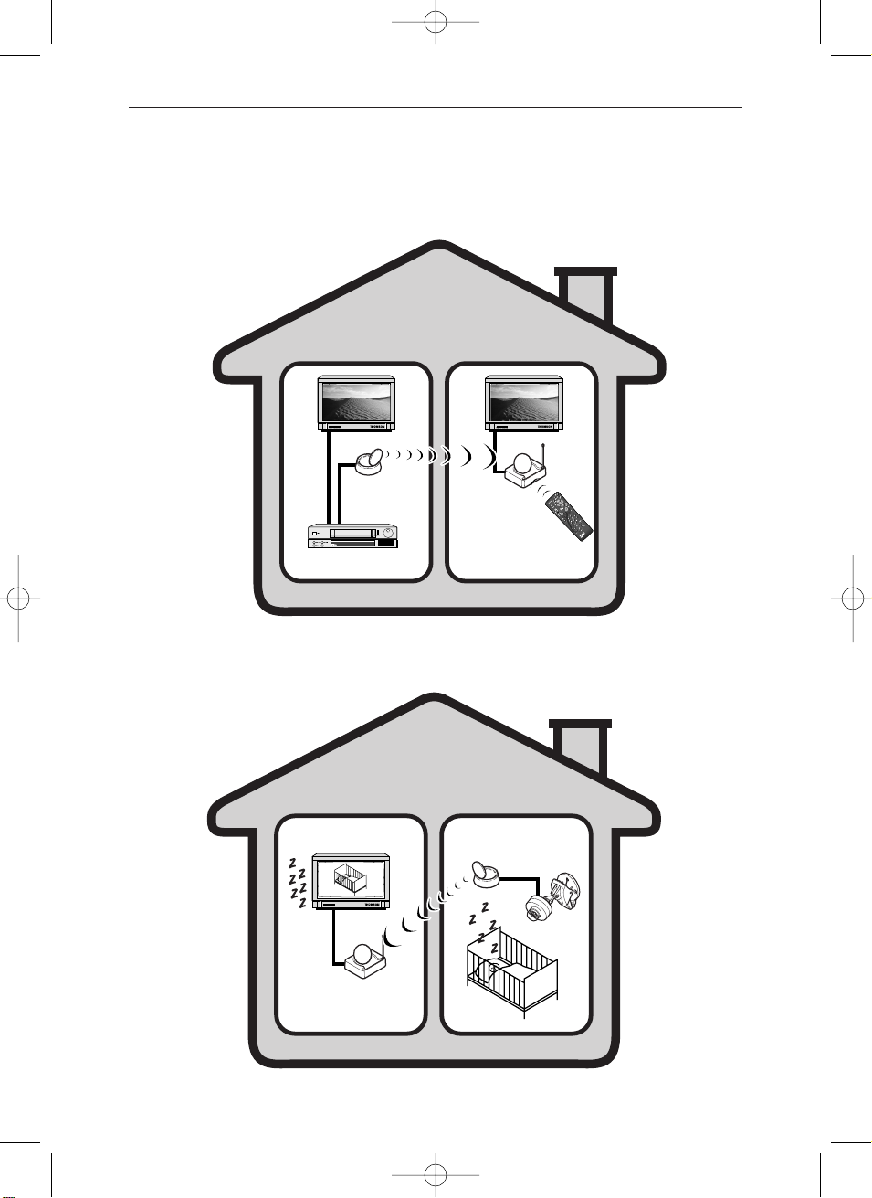
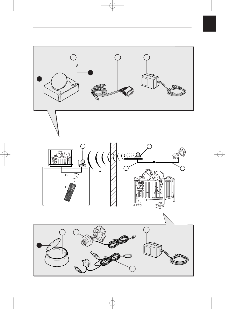
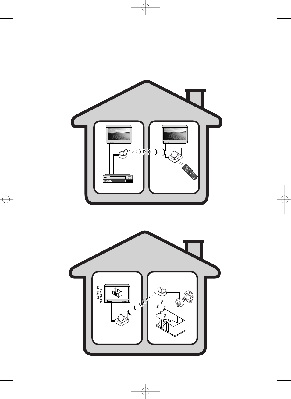
LIVING ROOM CHILDRENS’ ROOMS
Transmitter
Receiver
Camera
LIVING ROOM BEDROOM
Transmitter
Video recorder,
satellite receiver,...
Receiver
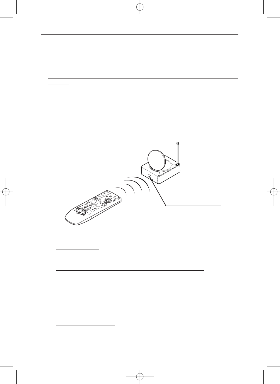
Remote control
for video recorder,
satellite receiver,…
or universal remote
control.
VS 540
VS 540 CA
Principles of operation
VS540CA 26/04/01 17:23 Page 2
GB
3
M
E
N
U
E
N
T
E
R
C
A
N
C
E
L
SELECT
POW
ER
STATUS
ON
/
STAND
BY
SO
URC
E
AU
TO
ADJUS
T
PC CA
RD
ACCESS
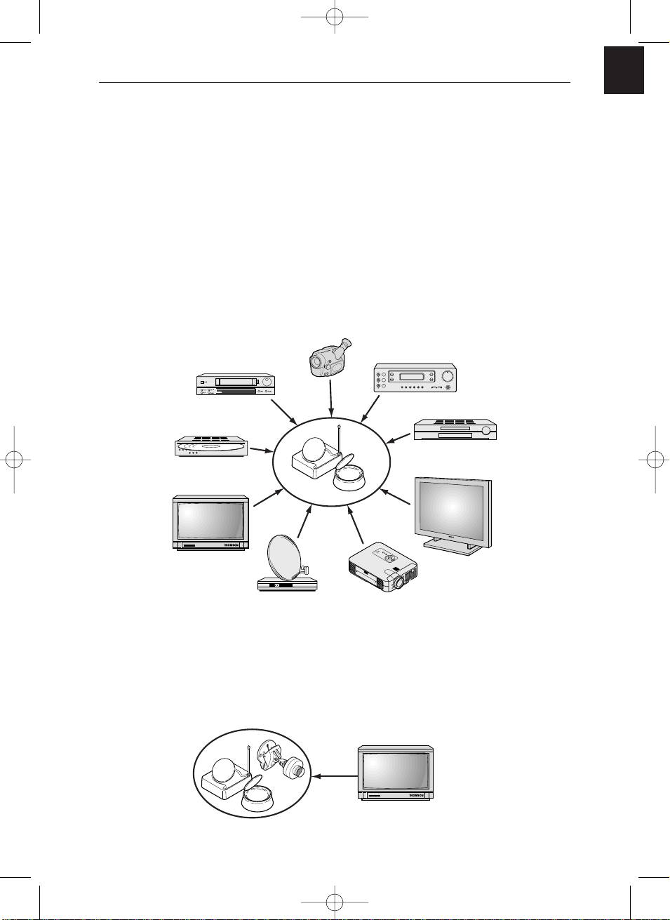
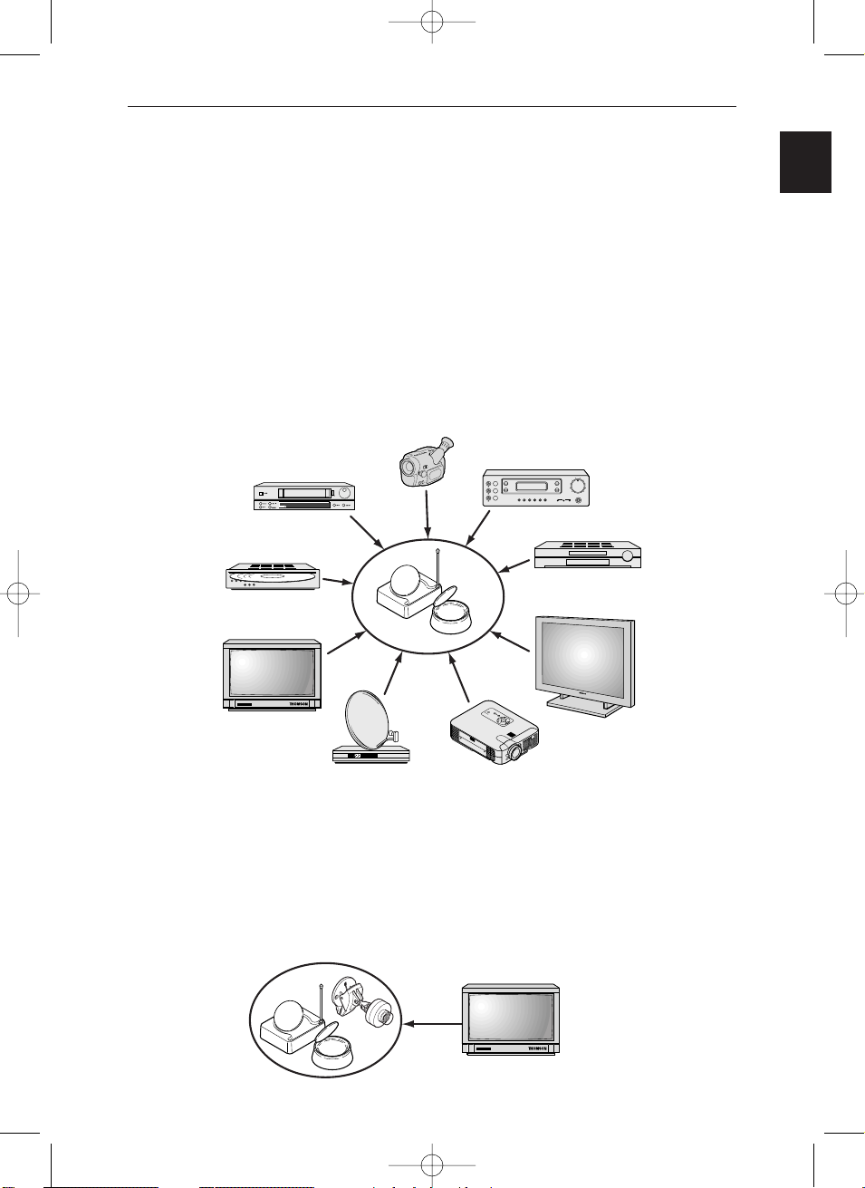
DVD player
Plasma screen monitor
Television set
VS 540 / E / U
VS 540 CA / CAE / CAU
Video recorder
Camcorder
Video disc player
Satellite/Cable receiver
and decoder
Video projector
A/V Amplifier
The Video Sender VS 540 permits the relay of an Audio-Video signal from your
main set-up to a second television set located in another room and equipped with a
scart connection (or RCA/Cinch). The main set-up is the place in which you have
chosen to install the majority of your equipment (television set, video recorder,
satellite receiver, DVD player,..) you can operate the units from the room with the
second television set by using their remote controls, or with a universal remote
control.
You can play and hear music if you connect the transmitter to a suitable outlet
(
AUDIO OUT), and the receiver to an amplifier (AUDIO IN) placed in another room. For
the link-up you will need to obtain 1 cinch/cinch cable (not supplied with
equipment).
If you already have a Thomson plasma screen monitor or video projector, the Video
Sender will ease your placing of these items where you most want them to be, thanks
to eliminating all problems related to long cable runs.
The Video Sender can be supplied complete with a mini camera itself equipped with
a microphone. This is the VS 540 CA assembly. With it you can for example monitor
a child’s room or the entry to your home. The handy camera fixing grip lets you
easily change where you place the assembly, as your needs change.The microphone
of the mini camera is built for voice-oriented transmission bandwidth giving quality
sound from whatever place you monitor.
What is this equipment for?
Television set
VS540CA 26/04/01 17:23 Page 3

4
VS 540
VIDEO IN
REMOTE
OUT
2,4Ghz
2
1
4
6
5
IR
B
3
4
1
A
2
A
Transmitter Receiver
Receiver
6
A
B
75
VS540CA 26/04/01 17:23 Page 4
GB
5
VS 540 CA
Transmitter
Receiver
L
8
9
A
3
1
Receiver
6
A
B
75
VS540CA 26/04/01 17:23 Page 5
5
8 9
2,4Ghz
1

6
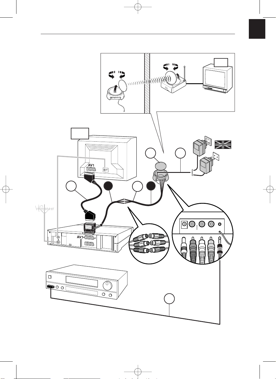
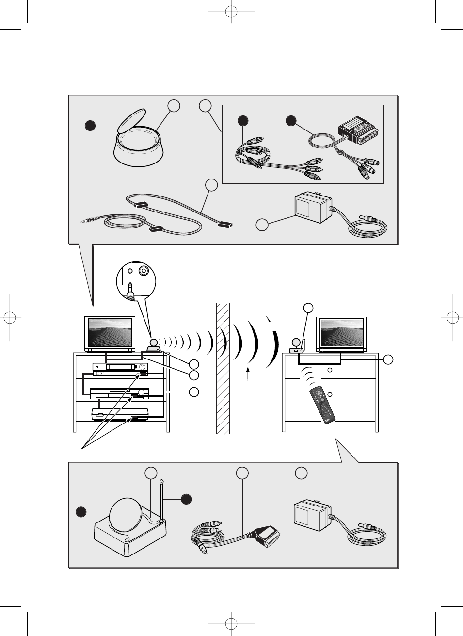
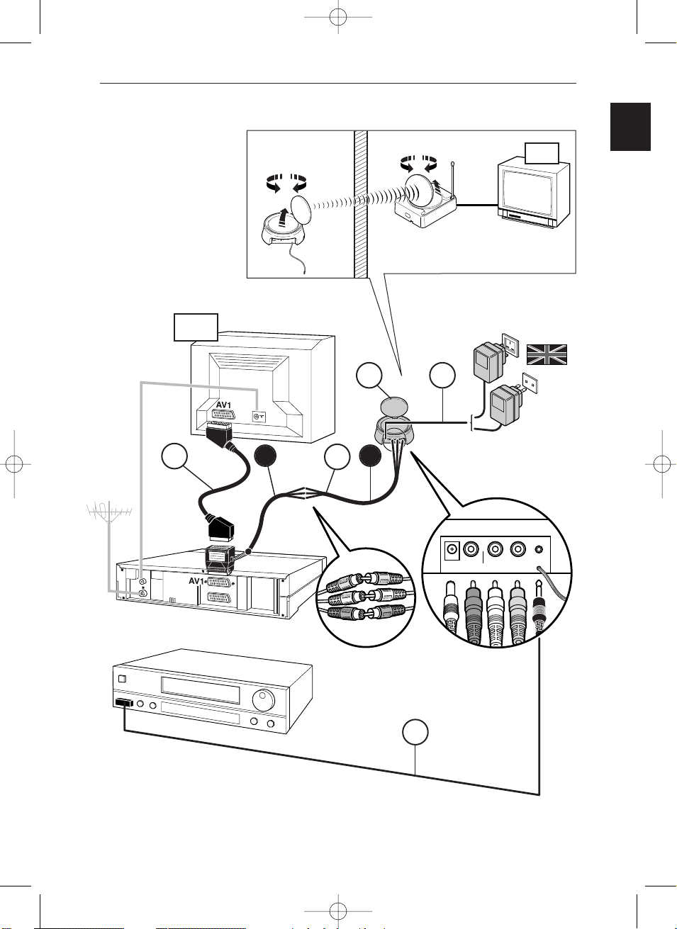
1. Place the transmitter (1) near the source equipment (VCR player, DVD player, etc.)
from which you want to transmit video or audio output, and connect it with the
two cords (2 A and 2 B) making sure you respect the color coding of the 3 cinch
plugs (red and white for audio, yellow for video). Connect the TV set to a suitable
outlet from the VCR player or DVD player (AV1).
Obtain a (non-supplied) SCART-TV set connector and connect the TV set to the 2B
adapter already connected to the VCR player or DVD player as shown on Page 7
(see item marked
*
on Page 7).
2. Carefully extend the antenna of the transmitter (1) and orient it towards the room
where your second TV set (TV2) is located. Turn on (position ON) the transmitter
and receiver, using the ON/OFF switch located on its lower side. Place the
channel selectors of the transmitter and the receiver on the same channel (same
letter).
3. Fit the lead (4) following these stages:
- connect the jack plug to the IR EXTEND socket,
- unwind the lead and place one cell near the infrared window of the unit to be
operated (video recorder or other),
- after installing the receiver (see Page 9), ask someone to use the remote control of
that equipment item to be controlled from the room where the second (TV2) is
located,
- by moving the cell around in front of the unit to be operated you will find the
location that permits its control from the other room. You must fix the cell in that
position. Usually, this will be a more or less large, transparent area located on the
front of the unit.
4. Remove the protective self-adhesive film from the infrared cell of cord (4) and affix
it to the infrared-sensitive panel of the equipment to be remote controlled. The
cordon has 3 cells in order to let you play video and audio from 3 equipment items
connected to the (TV1) set (see Diagram 2 on Page 13).
5. Fit the mains supply lead (3) to the transmitter and plug it into a 220/240 V ~ 50 Hz
mains power supply.
Installation of transmitter
- VS 540
VS540CA 26/04/01 17:23 Page 6
GB
7
AUDIO IN DC 12VVIDEO INIR OUT
LEFT RIGHT
AUDIO IN
DC 12V
VIDEO IN IR EXTENDLR
AUDIO IN
DC 12V
VIDEO INIR EXTENDLR
2
1 3
4
220/240V ~ 50 Hz
VS 540 U
VS 540 CAU
VS 540
VS 540 CA
VS 540 E
VS 540 CAE
TV1
TV2
*
A
B
VS540CA 26/04/01 17:23 Page 7
8
AUDIO IN
DC 12V
VIDEO INIR EXTENDLR
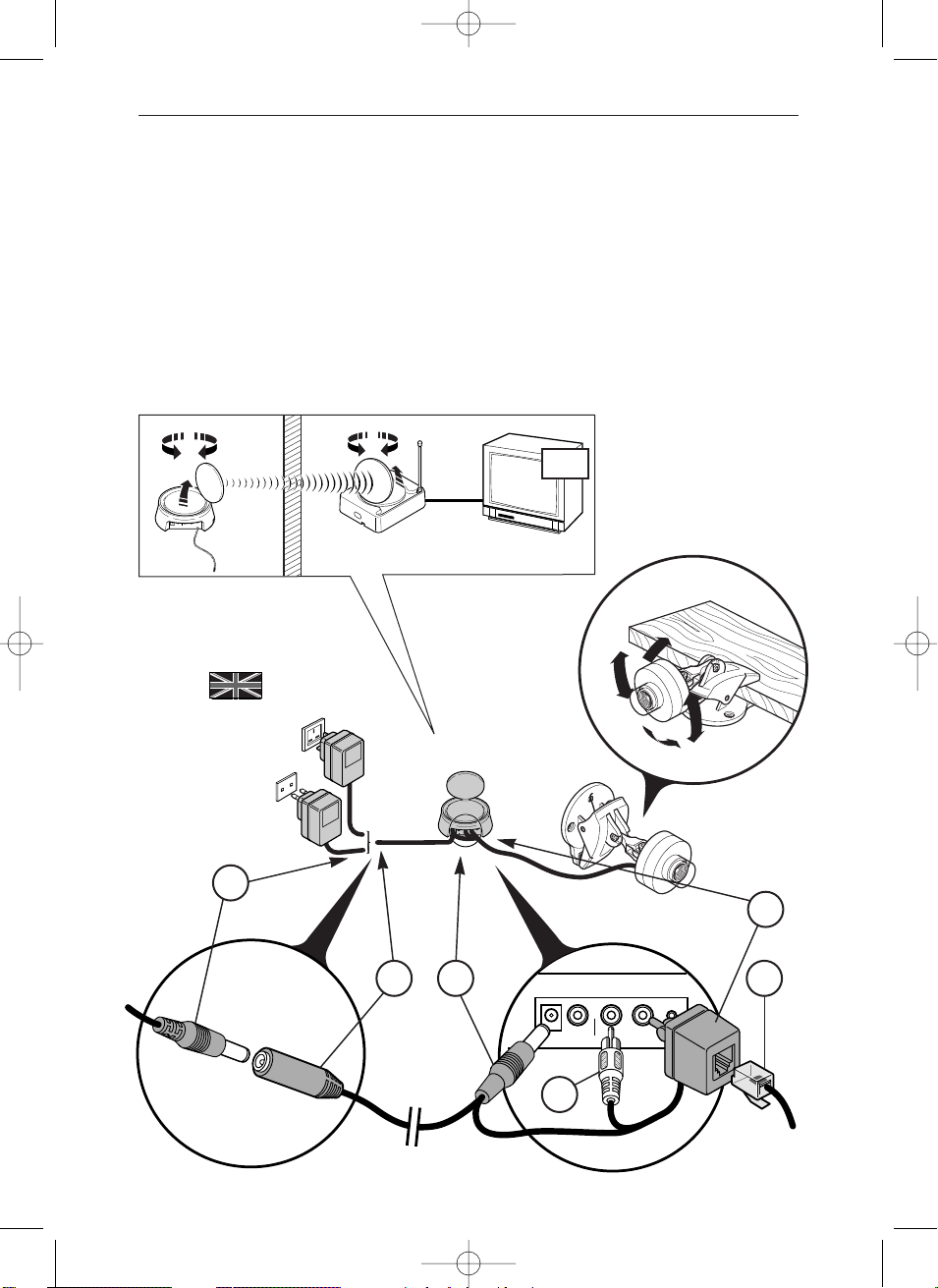
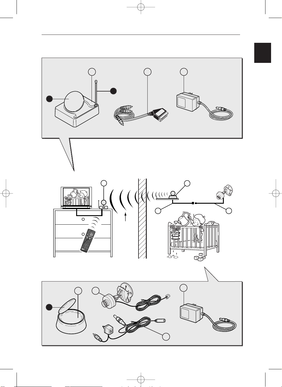
Installation of transmitter -
VS 540 CA
1 - Connect the video adaptor (1) to the VIDEO IN socket of the transmitter.
2 - Connect the camera jack (2) to the video adaptor socket (1).
3 - Connect the microphone jack (3) to the camera at the AUDIO IN L socket.
4 - Connect the power takeoff connector (4) to the 12 V DC source.
5 - Connect connector (6) to socket (5) and then plug the power takeoff to a mains
outlet (220-240 V AC ~ 50 Hz).
6 - Set the camera in the required position using the handy grip, or by attaching it
with two small screws (not supplied).
AUDIO IN
DC 12V
VIDEO IN IR EXTENDLR
AUDIO IN DC 12VVIDEO INIR OUT
LEFT RIGHT
220/240V ~ 50 Hz
VS 540 U
VS 540 CAU
VS 540
VS 540 E
VS 540 CA
VS 540 CAE
45
6
2
3
1
TV2
VS540CA 26/04/01 17:23 Page 8
GB
9
Receiver
Receiver
AUDIO OUT
L R
DC 12VVIDEO OUT
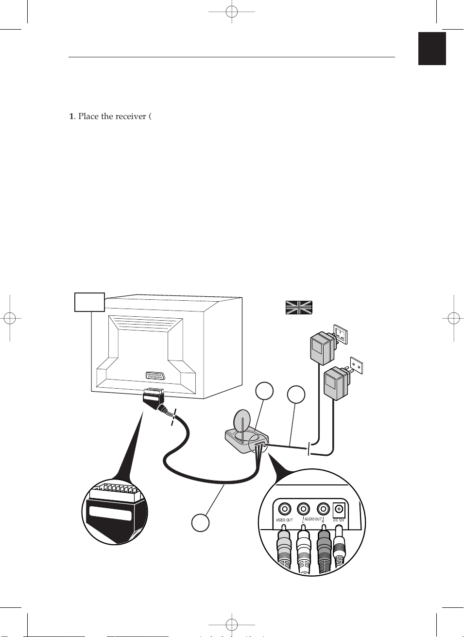
1. Place the receiver (5) on, or near, the second television set.
2. Connect the receiver (5) to the second television set using the lead (6) following
the same instructions as for the transmitter.
3. Extend the antenna on the receiver (5) and orient it toward the main TV set (TV1).
4. Raise and extend the telescopic aerial of the receiver (5)
.
5. Fit the mains supply lead (7) to the receiver and plug it into a 220/240 V ~ 50 Hz
mains power supply.
! THE ANTENNA allows you to transmit and receive audio and video signals over a
maximum range of 30 meters in free air environments. Inside a typical lodgment the
range will be less because of signal attenuation by building material absorption.
! THE TELESCOPIC AERIAL permits the control of the unit whose pictures you wish
to see in the room containing the second television set (TV2).
! THE POWER SUPPLY plug fitted to the transmitter (1) is not the same as the one
fitted to the receiver (7).
TV2
Installation of receiver
VS 540 or VS 540 CA
220/240V ~ 50 Hz
VS 540 U
VS 540 CAU
VS 540
VS 540 E
VS 540 CA
VS 540 CAE
5
6
7
VS540CA 26/04/01 17:23 Page 9
10
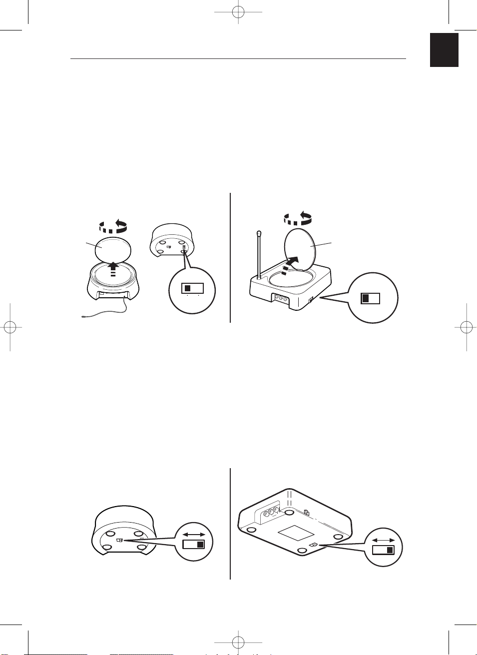
1. Switch on the transmitter (1) and the receiver (5) by switching their ON/OFF
buttons to the ON position.
2. Make sure that the transmitter and the receiver are set to the same
channel by checking the position of the selectors located under the
casing. They must be set to the same channel (same letter).
3. Switch on your equipment (television sets, video recorders ...) in both rooms.
4. VS 540: using the remote control of the unit whose pictures you wish to see, and
from the room containing the second television set (TV2), select the channels or
video functions (or others) according to the unit you are controlling.
5. VS 540 CA: move the camera to that position giving the best-oriented on your TV
screen.
Special operating details:
No pictur
e on TV2? If you fail to obtain the desired picture on the second television
set TV2, select the AV socket, to which the receiver (5) is connected, using the
television’s remote control.
Using a decoder (in France: Canal +, TPS, etc.) on your TV2
? To have clear
images on your second TV set (TV2), output from the decoder must pass through a
VCR player, placed in (AV2) mode or set to the channel number assigned for the
encrypted TV channel.
Use of a monitor
? If your second television set does not have a connection for an
outside aerial (terrestrial reception), or if it is a monitor, you will be able to see the
channels in the room containing the second television set by selecting those of the video
recorder with its remote control.
The pictur
e is scrambled? The running of certain equipment (micro-wave ovens,
digital telephone DECT, un-shielded acoustic loudspeakers, etc ...) may interfere with
signal transmission. Ensure that they are kept away from the transmitter and the
receiver or switch them off.
Make sure that you point the
remote control directly at the
receiver’s (5) infrared window.
Receiver
Instructions for use
VS540CA 26/04/01 17:23 Page 10
GB
11
You will obtain optimal service operation of your Video Sender by correctly
orienting the antennae (A). However, reflected signals or other signal degrading
factors can affect good quality signal transmission. In this case, readjust antennae
positions or slightly move the transmitter or receiver until you get crystal clear
reception.
AUDIO IN
DC 12V
VIDEO IN IR EXTENDLR
ON OFF
ON OFF
off
on
If no picture is obtained,
check that the transmitter and the receiver have not been installed in the reverse
order (each unit corresponds either to the input or to the output of the Audio-Video
signal). Check that they have been properly connected and that they are switched on
(ON position). Ensure that the channel selector is set to the same letter on both units.
If transmission is blurred or scrambled,
choose another channel but make sure that it is identical on both units.
CHANNEL
AUDIO OUT
L
R
DC 12VVIDEO OUT
Transmitter
Receiver
Transmitter
(A)
Receiver
Improvement of picture and sound
(A)
VS540CA 26/04/01 17:23 Page 11

12
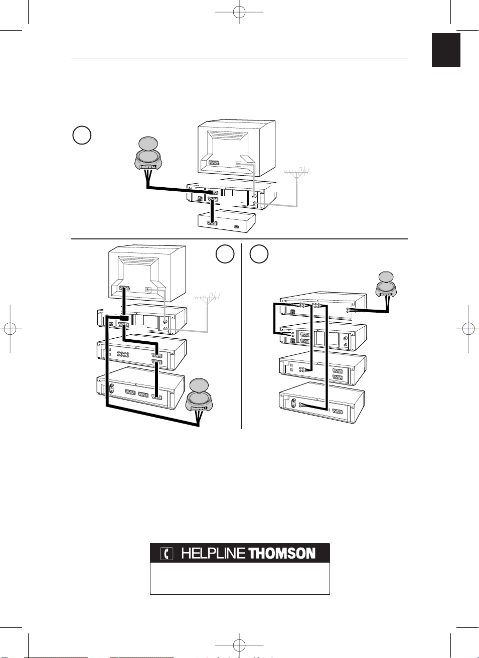
If you have several equipment items (VCR player, satellite receiver, DVD player, etc.)
in your main equipment room and want to transmit and receive audio and video
signals to a second TV set, connect your equipment items as shown in the Diagrams
on following pages. Usually, the units are connected in series, the last unit having a
free scart connection that you can use for the connection of the transmitter.
!
These diagrams represent some connection possibilities the operation of which depends on
the type of unit, its sockets and the signals it produces. There exist other connections that
you might perhaps wish to try if diagrams 1 to 3 here are not satisfactory. If this is the case,
ask your dealer for assistance.
!
As a general rule, remember to switch off units not in use. Also, refer to the manufacturers’
instructions to see if there are any particularities regarding connection or use. Certain units
may need to have their input scart connection “programmed”.
! I
n all cases the transmitter must be connected to a scart connection that produces an Audio-
Video signal Out. Refer to the manufacturer’s instructions for confirmation of this.
VS 540 -
Relay of pictures from
several units
VS540CA 26/04/01 17:23 Page 12
GB
13
VS 540-540U-540E/VS 540 CA-CAU-CAE/ISSUE2-GB/IC-RST/04-01
VS 540 -
General information on
connections...
Technical characteristics
Power supply: 12V DC
VS 540 / VS 540 CA : 4 channels (A : 2.411 GHz - B : 2.434 GHz - C : 2.454 GHz - D : 2.473 GHz )
VS 540 U / VS 540 CAU : 4 channels (A : 2.411 GHz - B : 2.434 GHz - C : 2.454 GHz - D : 2.473 GHz )
VS 540 E / VS 540 CAE : 3 channels (A : 2.421 GHz - B : 2.449 GHz - C : 2.477 GHz )
Remote control return: 433,92 MHz
Transmitter power: 10 mW
You can contact THOMSON by dialing: 0845 601 3093
(For Great-Britain, all calls will be charged at local rate)
www.thomson-europe.com
AUDIO IN DC 12VVIDEO INIR OUT
LEFT RIGHT
1
32
VCR
AV output
Audio amplifier
DVD
SAT
Transmitter
AUDIO IN DC 12VVIDEO INIR OUT
LEFT RIGHT
AUDIO IN DC 12VVIDEO INIR OUT
LEFT RIGHT
TV1
TV1
VCR
DVD
SAT
Transmitter
Satellite or Cable decoder
(Canal+, Canal Sat,TPS, Premiere,Telepiu,Via Digital…)
VCR
AV1
AV2
AUDIO
AV1
AV2
Transmitter
VS540CA 26/04/01 17:23 Page 13

14
Note
VS540CA 26/04/01 17:23 Page 14
F
1
Transmetteur vidéo sans fil
Précautions
• Sécurité
Les composants de cet appareil sont sensibles à la chaleur. La température maximale
ambiante ne doit pas dépasser 35° Celsius.
L’humidité des locaux où est placé l’appareil ne doit pas dépasser un taux
hygrométrique de 85 %. Evitez de l’exposer à l’eau de pluie ou aux éclaboussures.
La caméra (VS 540 CA) est “Splashproof”, elle supporte les éclaboussures et
l’humidité. Toutefois ne l’exposez pas à la pluie et au ruissellement. Le passage d’une
atmosphère froide à une ambiance chaude peut provoquer de la
condensation. Laissez-la disparaître d’elle-même avant de remettre l’appareil en
marche.
En cas d’absence prolongée, éteignez l’appareil avec l’interrupteur marche/arrêt.
Même à l’arrêt, certains composants restent en contact avec le réseau électrique. Pour
l’isoler complètement vous devez débrancher la fiche d’alimentation de la prise
secteur.
En cas d’orage, il est recommandé d’isoler l’appareil du réseau électrique afin de ne
pas le soumettre à des surcharges électriques ou électromagnétiques qui peuvent
l’endommager. A cette fin, laissez la fiche secteur accessible pour le débrancher.
Débranchez immédiatement l’appareil si vous constatez qu’il dégage une odeur de
brûlé ou de la fumée. En aucun cas vous ne devez ouvrir l’appareil vous-même,
vous risquez l’électrocution.
• Entretien
Nettoyez l’appareil avec un chiffon doux et un détergent neutre. L’utilisation de
solvants, de produits abrasifs ou de produits à base d’alcool risque d’endommager
l’appareil.
• Réglementation
Cet appareil ne doit être installé qu'à l'intérieur d'un local. Son utilisation est
restreinte aux transmissions radioélectriques privées. Le branchement à un réseau
public ou indépendant ou à une antenne extérieure est interdit.
Cet appareil ne doit en aucun cas être utilisé à des fins commerciales. Il est
uniquement prévu pour un usage domestique.
THOMSON multimedia dégage sa responsabilité en cas d’utilisation non conforme aux
indications de cette notice.
VS540CA 26/04/01 17:23 Page 1
2
SALON CHAMBRE D’ENFANT
Transmitter
(Émetteur)
Receiver
(Récepteur)
Caméra
SALON CHAMBRE
Transmitter
(Émetteur)
Magnétoscope,
Récepteur satellite, ...
Receiver
(Récepteur)
Télécommande
du magnétoscope,
récepteur satellite...
ou télécommande
universelle.
VS 540
VS 540 CA
Principes de fonctionnement
VS540CA 26/04/01 17:23 Page 2
F
3
M
E
N
U
E
N
T
E
R
C
A
N
C
E
L
SELECT
POW
ER
STATUS
ON
/
STAND
BY
SO
URC
E
AU
TO
ADJUS
T
PC CA
RD
ACCESS
DVD
Moniteur plasma
TV
VS 540 / E / U
VS 540 CA / CAE / CAU
Magnétoscope
Camescope
Lecteur Video-disc
Récepteur et décodeur
Satellite/Câble
Vidéo projecteur
Amplificateur A/V
Le Video Sender VS 540 permet de diffuser un signal Audio-Video à partir de votre
installation principale vers un second téléviseur installé dans une autre pièce et
équipé d’une prise péritélévision (ou RCA/Cinch). L’installation principale est
l’endroit où vous avez regroupé la plupart de vos appareils (téléviseur,
magnétoscope, récepteur satellite, lecteur DVD, ...). Vous pourrez commander les
appareils depuis la pièce où se trouve le second téléviseur à l’aide de leurs
télécommandes, ou avec une télécommande universelle.
La diffusion de musique est possible si vous raccordez l’émetteur à une
source (
AUDIO OUT) et le récepteur à un amplificateur (AUDIO IN) dans une autre
pièce. Dans ce cas vous devrez vous procurer 1 câble cinch / cinch non fourni.
Si vous possédez un moniteur plasma ou un projecteur vidéo Thomson, le Video
Sender vous facilitera leur implantation à l’endroit désiré grâce à l’élimination des
problèmes liés à la longueur des câbles de connexions.
Le Video Sender peut être livré avec une mini-caméra, elle-même munie d’un
microphone. Cet ensemble constitue le VS 540 CA. Il vous permet de surveiller par
exemple, la chambre d’un enfant ou encore l’entrée de votre habitation. Grâce à la
pince de la caméra vous pourrez facilement modifier son emplacement et l’adapter
selon le besoin du moment. Le microphone de la mini-caméra permet d’entendre le
son de l’endroit surveillé avec une qualité correspondante à la bande passante
généralement affectée à la voix.
A quoi sert cet appareil ?
TV
VS540CA 26/04/01 17:23 Page 3
4
VS 540
B
3
4
1
A
2
A
Transmitter Receiver
Receiver
6
A
B
75
VS540CA 26/04/01 17:24 Page 4
REMOTE
VIDEO IN
OUT
5
1
2
4
2,4Ghz
6
IR
F
5
VS 540 CA
Transmitter
Receiver
L
8
9
A
3
1
Receiver
6
A
B
75
VS540CA 26/04/01 17:24 Page 5
5
8 9
1
2,4Ghz

6
1. Placez l’émetteur (1) à proximité de l’appareil (magnétoscope, lecteur DVD…)
dont vous souhaitez diffuser les images et le son et raccordez-le à l’aide des deux
cordons (2 A et 2 B) en respectant les couleurs des 3 fiches cinch (rouge et blanche
pour l’audio, jaune pour la vidéo). Raccordez la fiche péritélévision à une prise du
magnétoscope ou du lecteur DVD (AV1).
Procurez-vous un cordon SCART-Péritélévision (non fourni) et raccordez le
téléviseur à l’adaptateur 2B déjà branché au magnétoscope ou lecteur DVD (voir
repère
*
de la page 7).
2. Déployez l’antenne de l’émetteur (1) avec précaution et orientez-la en direction de
la pièce du second téléviseur (TV2). Mettez en marche (position ON) l’émetteur et
le récepteur à l’aide du bouton ON/OFF situé en dessous et sur le coté. Placez le
sélecteur de canal de l’émetteur et du récepteur sur la même position (même
lettre).
3. Installez le cordon (4) en suivant ces étapes :
- raccordez la fiche jack dans la prise IR EXTEND,
- déroulez le cordon et placez une cellule à proximité de la fenêtre infrarouge de
l'appareil à commander,
- après l’installation du récepteur (voir page 9), demandez à une personne
d'utiliser la télécommande de l'appareil à commander depuis la pièce où se trouve
le second téléviseur (TV2),
- en déplaçant la cellule devant l'appareil à commander vous pourrez déterminer
l'emplacement qui permet sa commande depuis l'autre pièce. Vous devrez y coller
la cellule. Généralement il s'agit d'une zone transparente plus ou moins grande
située en façade.
4. Enlevez le papier de protection de la partie auto-collante de la cellule infrarouge
du cordon (4) et collez-la sur la fenêtre infrarouge de l’appareil à télécommander.
Le cordon est équipé de 3 cellules afin de vous permettre de diffuser les images et
le son de 3 appareils connectés au téléviseur (TV1) (voir schéma 2 de la page 13).
5. Branchez l’alimentation secteur (3) à l’émetteur et à une prise secteur 220/240V ~
50 Hz.
Installation de l’émetteur
- VS 540
VS540CA 26/04/01 17:24 Page 6
F
7
AUDIO IN DC 12VVIDEO INIR OUT
LEFT RIGHT
AUDIO IN
DC 12V
VIDEO IN IR EXTENDLR
AUDIO IN
DC 12V
VIDEO INIR EXTENDLR
2
1 3
4
220/240V ~ 50 Hz
VS 540 U
VS 540 CAU
VS 540
VS 540 CA
VS 540 E
VS 540 CAE
TV1
TV2
*
A
B
VS540CA 26/04/01 17:24 Page 7

8
AUDIO IN
DC 12V
VIDEO INIR EXTENDLR
Installation de l’émetteur -
VS 540 CA
1 - Branchez l’adaptateur vidéo (1) dans la prise VIDEO IN de l’émetteur.
2 - Branchez la fiche (2) de la caméra dans la prise de l’adaptateur vidéo (1).
3 - Branchez la fiche (3) du microphone de la caméra dans la prise AUDIO IN L.
4 - Branchez la fiche d’alimentation (4) dans la prise DC 12V.
5 - Branchez la fiche (6) dans la fiche (5) puis branchez l’alimentation secteur dans
une prise 220 / 240V ~ 50 Hz.
6 - Installez la caméra en la positionnant avec sa pince ou en la fixant à l’aide de 2
petites vis (non fournies).
AUDIO IN
DC 12V
VIDEO IN IR EXTENDLR
AUDIO IN DC 12VVIDEO INIR OUT
LEFT RIGHT
220/240V ~ 50 Hz
VS 540 U
VS 540 CAU
VS 540
VS 540 E
VS 540 CA
VS 540 CAE
45
6
2
3
1
TV2
VS540CA 26/04/01 17:24 Page 8
 Loading...