


CABLE
SATELLITE |
TELECOM |
TERRESTRIAL |
TCW770 - Wireless Gateway
User manual
|
Chapter 1: Connections and Setup |
CAUTION |
CAUTION |
Disconnect power before |
To ensure reliable operation and to prevent |
servicing. |
overheating, provide adequate ventilation for this |
|
modem and keep it away from heat sources. Do |
|
not locate near heat registers or other |
|
heat-producing equipment. Provide for free air |
|
flow around the Wireless Gateway and its power |
|
supply. |
This symbol means that your inoperative electronic appliance must be collected separately and not mixed with the household waste. The European Union has implemented a specific collection and recycling system for which producers are responsible.
This appliance has been designed and manufactured with high quality materials and components that can be recycled and reused. Electrical and electronic appliances are liable to contain parts that are necessary in order for the system to work properly but which can become a health and environmental hazard if they are not handled or disposed of in the proper way. Consequently, please do not throw out your inoperative appliance with the household waste.
If you are the owner of the appliance, you must deposit it at the appropriate local collection point or leave it with the vendor when buying a new appliance.
-If you are a professional user, please follow your supplier's instructions.
-If the appliance is rented to you or left in your care, please contact your service provider. Help us protect the environment in which we live !
NORTH AMERICAN CABLE INSTALLER:
This reminder is provided to call your attention to Article 820.93 of the National Electrical Code (Section 54 of the Canadian Electrical Code, Part 1) which provides guidelines for proper grounding and, in particular, specifies that the cable ground shall be connected to the grounding system of the building as close to the point of cable entry as practical.
i
Illustrations contained in this document are for representation only.

Important Information
EURO-DOCSIS compliant
This product was designed according to Data over Cable Service Interface Specifications.
Operating Information |
|
Operating Temperature: 0˚ C to 40˚ C |
(32˚ F ~ 104˚ F) |
Storage Temperature: -20˚ C to 70˚ C |
(-4˚ F ~ 158˚ F) |
If you purchased this product at a retail outlet, please read the following:
Product Information
Keep your sales receipt to obtain warranty parts and service and for proof of purchase. Attach it here and record the serial and model numbers in case you need them. The numbers are located on the back of the product.
Model No. ____________________________Serial No ________________________________
Purchase Date: ________________________Dealer/Address/Phone: _________________________
ii
Illustrations contained in this document are for representation only.

List of Figures |
|
Chapter 1: Connections and Setup...................................................................................................................... |
2 |
Introduction ........................................................................................................................................................... |
2 |
Wireless Gateway Features ............................................................................................................................ |
2 |
What’s on the CD-ROM ................................................................................................................................ |
2 |
EURO-DOCSIS is trademarks of Cable Television Laboratories, Inc. ............................................................ |
3 |
Computer Requirements................................................................................................................................. |
3 |
Wall Mounting............................................................................................................................................... |
4 |
Wireless Gateway TCW770 Overview ................................................................................................................... |
5 |
Front Panel .................................................................................................................................................... |
5 |
Rear Panel ..................................................................................................................................................... |
7 |
Side Panel ...................................................................................................................................................... |
7 |
Relationship among the Devices ............................................................................................................................ |
8 |
What the Modem Does................................................................................................................................... |
8 |
What the Modem Needs to Do Its Job ............................................................................................................ |
8 |
Contact Your Local Cable Company .............................................................................................................. |
8 |
Connecting the Wireless Gateway to a Single Computer ...................................................................................... |
10 |
Attaching the Cable TV Wire to the Wireless Gateway................................................................................. |
10 |
Important Connection Information ............................................................................................................... |
11 |
Ethernet Connection to a Computer .............................................................................................................. |
11 |
Connecting More Than One Computer to the Wireless Gateway................................................................... |
12 |
Turning on the Wireless Gateway......................................................................................................................... |
13 |
Chapter 2: WEB Configuration ........................................................................................................................ |
13 |
Accessing the Web Configuration ........................................................................................................................ |
13 |
Outline of Web Manager .............................................................................................................................. |
14 |
Status................................................................................................................................................................... |
15 |
1. Software................................................................................................................................................... |
15 |
iii |
|
Illustrations contained in this document are for representation only. |
|

|
List of Figures |
|
2. |
Connection............................................................................................................................................... |
16 |
3. |
Password.................................................................................................................................................. |
17 |
4. |
Diagnostics .............................................................................................................................................. |
18 |
5. |
Event Log ................................................................................................................................................ |
19 |
6. |
Initial Scan............................................................................................................................................... |
20 |
7. |
Backup/Restore........................................................................................................................................ |
21 |
Network .............................................................................................................................................................. |
22 |
|
1. |
LAN ........................................................................................................................................................ |
22 |
2. WAN ....................................................................................................................................................... |
23 |
|
3. |
Computers................................................................................................................................................ |
24 |
4. DDNS...................................................................................................................................................... |
25 |
|
5. |
Time ........................................................................................................................................................ |
26 |
Advanced ............................................................................................................................................................ |
27 |
|
1. |
Options .................................................................................................................................................... |
27 |
2. |
IP Filtering............................................................................................................................................... |
28 |
3. |
MAC Filtering ......................................................................................................................................... |
29 |
4. |
Port Filtering............................................................................................................................................ |
30 |
5. |
Forwarding .............................................................................................................................................. |
31 |
6. |
Port Triggers ............................................................................................................................................ |
32 |
7. |
DMZ Host................................................................................................................................................ |
33 |
8. |
RIP (Routing Information Protocol) Setup ................................................................................................ |
34 |
Firewall ............................................................................................................................................................... |
35 |
|
1. |
Web Filtering ........................................................................................................................................... |
35 |
2. |
TOD Filtering .......................................................................................................................................... |
36 |
3. |
Local Log and Remote Log ...................................................................................................................... |
37 |
Parental Control................................................................................................................................................... |
38 |
|
|
iv |
|
|
Illustrations contained in this document are for representation only. |
|

|
|
List of Figures |
1. |
Basic........................................................................................................................................................ |
38 |
Wireless............................................................................................................................................................... |
39 |
|
1. 802.11/ Radio ........................................................................................................................................... |
40 |
|
2. |
802.11/ Primary Network ......................................................................................................................... |
41 |
3. |
Access Control ......................................................................................................................................... |
48 |
4. |
802.11/ Advanced .................................................................................................................................... |
49 |
5. |
Bridging................................................................................................................................................... |
51 |
6. |
802.11 QoS (WMM) Settings ................................................................................................................... |
52 |
Chapter 3: Networking ...................................................................................................................................... |
54 |
|
Communications .......................................................................................................................................... |
54 |
|
Type of Communication............................................................................................................................... |
54 |
|
Cable Modem (CM) Section......................................................................................................................... |
55 |
|
Networking Section ..................................................................................................................................... |
55 |
|
Three Networking Modes............................................................................................................................. |
56 |
|
Cable Modem (CM) Mode ........................................................................................................................... |
56 |
|
Residential Gateway (RG) Mode.................................................................................................................. |
58 |
|
CableHome (CH) Mode ............................................................................................................................... |
59 |
|
MAC and IP Addresses Summary ................................................................................................................ |
61 |
|
Chapter 4: Additional Information ................................................................................................................... |
62 |
|
Frequently Asked Questions......................................................................................................................... |
62 |
|
Service Information ............................................................................................................................................. |
66 |
|
Glossary .............................................................................................................................................................. |
67 |
|
v
Illustrations contained in this document are for representation only.

Chapter 1: Connections and Setup
Chapter 1: Connections and Setup
Introduction
Wireless Gateway Features
CableLabs DOCSIS /EuroDOCSIS 1.0/1.1/2.0/3.0 Standard Compliant
4 x Standard RJ-45 connector for 10/100/1000 BaseT Ethernet with auto-negotiation and MDIX functions; Support maximum Ethernet cable length up to 100m (Category 5)
1 x Master USB connector socket comply to USB2.0
WIFI interface 802.11n; 2,4GHz or 5 GHz with at least 2x2 antennas.
Transparent bridging for IP traffic
Transparent bridging between CPE and RF interface
Transparent bridging between Ethernet and USB interface when USB is populated on the board
RSA and 56 bit DES data encryption security
SNMP network management support
Remote operating firmware downloading
Support Web pages and private DHCP server for status monitoring
MPEG over IP encapsulation
Power management
Network Protocol: IP/TCP/UDP/ARP/ICMP/DHCP/FTP/TFTP/SNMP/HTTP
Syslog (remote)
Event Log (local)
Clear LED display
Reset switch in order to restore factory parameters
Two detachable SMA antennas connectors (optional)
What’s on the CD-ROM
Insert the Wireless Gateway CD-ROM into your CD-ROM drive to view troubleshooting tips, the internal diagnostics, and other valuable information.
CD-ROM Contents:
Electronic copy of this user’s guide in additional languages (PDF format)
Adobe Acrobat Reader — application you can load to read PDF format, if you don’t have it loaded already
Links to Thomson web site
2
Illustrations contained in this document are for representation only.

Chapter 1: Connections and Setup
EURO-DOCSIS is trademarks of Cable Television Laboratories, Inc.Computer Requirements
For the best possible performance from your Wireless Gateway, your personal computer must meet the following minimum system requirements (note that the minimum requirements may vary by cable companies):
|
IBM PC COMPATIBLE |
MACINTOSH** |
|
|
|
CPU |
Pentium preferred |
PowerPC or higher |
|
|
|
System RAM |
16MB (32MB preferred) |
24MB (32MB preferred) |
|
|
|
Operating System |
Windows* |
Mac OS** 7.6.1 or higher |
|
NT/2000/Me/XP/Vista/7, Linux |
|
|
|
|
Video |
VGA or better (SVGA preferred) |
VGA or better (SVGA built-in |
|
|
preferred) |
|
|
|
Ethernet |
10 /100 /1000 Base-T |
10 /100 /1000 Base-T |
|
|
|
|
An Ethernet card makes it possible for your computer to pass data to and |
|
|
from the internet. You must have an Ethernet card and software drivers |
|
|
installed in your computer. You will also need a standard Ethernet cable to |
|
|
connect the Ethernet card to your Wireless Gateway. |
|
|
|
|
Software |
A TCP/IP network protocol for each machine |
|
Microsoft Internet Explorer 4.0 or later or Netscape Navigator 4.0 or later. (5.0 and 4.7 or later, respectively, are strongly recommended.)
*Windows is a trademark of Microsoft Corporation.
**Macintosh and the Mac OS are trademarks of Apple Computer, Inc.
3
Illustrations contained in this document are for representation only.

Chapter 1: Connections and Setup
Wall Mounting
This article will show the user through the process of wall-mounting the Wireless Gateway The Adapter has two wall-mount slots on its back panel.
Two screws are needed to mount the Adapter.
To do this:
1.Ensure that the wall you use is smooth, flat, dry and sturdy and use the 2 screw holes which are 101.6 mm apart from each other.
2.Fix the screws into wall, leaving their heads 3 mm (0.12 inch) clear of the wall surface.
3.Remove any connections to the unit and locate it over the screw heads. When in line, gently push the unit on to the wall and move it downwards to secure.
4
Illustrations contained in this document are for representation only.

Chapter 1: Connections and Setup
Wireless Gateway TCW770 Overview
Front Panel
The following illustration shows the front panel of the TCW770 gateway:
Reset Button behavior
a)Push and hold the button between 0 and 5 seconds Reboot the device
b)Between 6 and 10 seconds Display the channel bonding status for DS and US Note: This is the same as the above Channel Bonding display after the registration
c)After 11 seconds Perform the factory reset.
WPS LED is a backlight in WPS button
d)When WiFi is on, the LED is blinking
e)When WPS association is on, the LED is turned on
5
Illustrations contained in this document are for representation only.
Chapter 1: Connections and Setup
The LEDs on the front panel are described in the table below (from left to right):
|
|
Internet |
|
Ethernet |
|
|
|
|
|
|
|
||
TCW770 |
Power |
|
|
|
USB Wireless |
Description |
|
|
|
|
|
|
|
DS |
US |
Online |
1 |
2 |
3 |
4 |
|
ON |
ON |
ON |
ON |
ON |
ON |
ON |
ON |
X |
X |
Power on 0.25 sec |
Boot-up |
|
|
|
|
|
|
|
|
|
|
|
Operation |
|
|
|
|
|
|
|
|
|
|
|
X |
FLASH |
FLASH |
FLASH |
X |
X |
X |
X |
X |
X |
From power ON to system initialization |
|
|
|
||||||||||
|
|
|
|
|
|
|
|
|
|
|
complete |
|
|
|
|
|
|
|
|
|
|
|
|
|
ON |
FLASH |
OFF |
OFF |
X |
X |
X |
X |
X |
X |
During DS scanning and acquiring SYNC |
|
|
|
|
|
|
|
|
|
|
|
|
|
ON |
ON |
FLASH |
OFF |
X |
X |
X |
X |
X |
X |
From SYNC completed, receiving UCD to ranging |
|
|
||||||||||
DOCSIS Start-up |
|
|
|
|
|
|
|
|
|
|
completed |
Operation |
|
|
|
|
|
|
|
|
|
|
|
ON |
ON |
ON |
FLASH |
X |
X |
X |
X |
X |
X |
During DHCP, configuration file download, |
|
|
|
|
|
|
|
|
|
|
|
|
|
|
ON |
ON |
ON |
ON |
X |
X |
X |
X |
X |
X |
Operational (NACO=ON) |
|
|
|
|
|
|
|
|
|
|
|
|
|
ON |
FLASH |
FLASH |
OFF |
X |
X |
X |
X |
X |
X |
Operational (NACO=OFF) |
|
|
|
|
|
|
|
|
|
|
|
|
|
|
|
|
|
|
|
|
|
|
|
Wait registration with all DS and all US – Lights |
|
FLASH |
FLASH |
FLASH |
FLASH |
X |
X |
X |
X |
X |
X |
Flash sequentially from the right to left |
|
|
|
|
|
|
|
|
|
|
|
|
|
|
|
|
|
|
|
|
|
|
|
Minimum duration 3 seconds |
|
|
|
|
|
|
|
|
|
|
|
From 1 to 4 DS, from 1 to 4 LEDs are ON. |
|
X |
X |
X |
X |
X |
X |
X |
X |
X |
X |
From 5 to 8 DS, From 1 to 4 LEDs are flashing |
|
|
|
|
|
|
|
|
|
|
|
|
Channel Bonding |
|
|
|
|
|
|
|
|
|
|
Duration 3 seconds |
|
|
|
|
|
|
|
|
|
|
|
|
Operation |
|
|
|
|
|
|
|
|
|
|
|
|
|
|
|
|
|
|
|
|
|
From 1 to 2 US, from 1 to 2 LEDs are ON. |
|
|
|
|
|
|
|
|
|
|
|
|
|
|
OFF |
X |
X |
OFF |
X |
X |
X |
X |
X |
X |
From 3 to 4 US, From 1 to 2 LEDs are flashing |
|
|
|
|
|
|
|
|
|
|
|
|
|
|
|
|
|
|
|
|
|
|
|
Duration 3 seconds. |
|
|
|
|
|
|
|
|
|
|
|
|
|
|
|
|
|
|
|
|
|
|
|
Wait registration with all DS and all US – Lights |
|
FLASH |
FLASH |
FLASH |
FLASH |
X |
X |
X |
X |
X |
X |
Flash sequentially from the left to right |
|
|
|
|
|
|
|
|
|
|
|
|
|
|
|
|
|
|
|
|
|
|
|
Minimum duration 3 seconds |
|
|
|
|
|
|
|
|
|
|
|
|
|
|
|
|
|
OFF |
OFF |
OFF |
OFF |
|
|
No Ethernet Link |
|
ON |
X |
X |
X |
ON |
ON |
ON |
ON |
X |
X |
Ethernet Link |
|
|
|
|
|
|
|
|||||
CPE Operation |
|
|
|
|
FLASH FLASH FLASH FLASH |
|
|
TX/RX Ethernet Traffic |
|||
|
|
|
|
|
|
|
|
|
|
|
|
|
|
|
|
|
|
|
|
|
|
OFF |
Wireless is disable |
|
ON |
X |
X |
X |
X |
X |
X |
X |
X |
|
Wireless initiate success or enable |
|
ON |
||||||||||
|
|
|
|
|
|
|
|
|
|
||
|
|
|
|
|
|
|
|
|
|
|
TX/RX Wireless Traffic |
|
|
|
|
|
|
|
|
|
|
FLASH |
|
|
|
|
|
|
|
|
|
|
|
|
|
|
|
|
|
|
|
|
|
|
OFF |
|
No USB Link |
USB Operation |
ON |
X |
X |
X |
X |
X |
X |
X |
ON |
X |
USB Link |
|
|
|
|
|
|
|
|
|
FLASH |
|
TX/RX USB Traffic |
|
|
|
|
|
|
|
|
|
|
|
|
SW Download |
|
|
|
|
|
|
|
|
|
|
A software download and while updating the |
|
ON |
FLASH |
FLASH |
ON |
X |
X |
X |
X |
X |
X |
|
Operation |
|
|
|
|
|
|
|
|
|
|
FLASH memory |
6
Illustrations contained in this document are for representation only.
Chapter 1: Connections and Setup
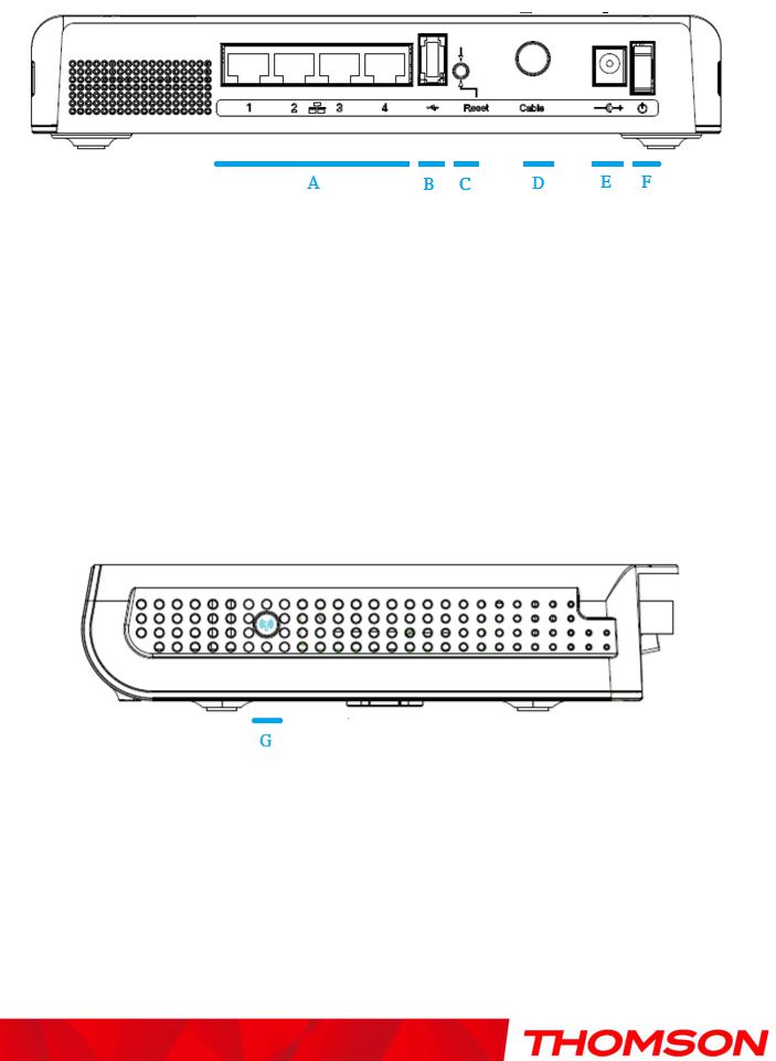
Rear Panel
A |
ETHERNET 1 2 3 4: |
4x Ethernet 10/100/1000 Mbps RJ-45 connectors |
|
B |
USB Host: |
1x USB 2.0 Connector |
|
C |
Reset: |
1x |
Reset or reset to factory default this Wireless Gateway |
D |
CABLE: |
1x |
F-Connector for the coax cable |
E |
12VDC : |
1x Power connector to connect the DC power supply |
|
F |
Power switch: |
1x switch to power on/off this Wireless Gateway |
|
Side Panel
G WPS & WiFi on/off button: 1x button with two features:
to activate/disable the WiFi, to execute a WPS association
7
Illustrations contained in this document are for representation only.

Chapter 1: Connections and Setup
Relationship among the Devices
What the Modem Does
The Wireless Gateway provides high-speed Internet access as well as cost-effective fax/modem services over residential, commercial, and education subscribers on public and private networks via an existing CATV infrastructure. The IP traffic can transfer between the Wireless Gateway and EURO-DOCSIS compliant head-end equipment. The data security secures upstream and downstream communications.
What the Modem Needs to Do Its Job
The Right Cable Company: Make sure your local cable company provides data services that use cable TV industry-standard EURO-DOCSIS compliant technology.
Contact Your Local Cable Company
You will need to contact your cable company to establish an Internet account before you can use your gateway. You should have the following information ready (which you will find on the sticker on the gateway):
The serial number
The model number
The Cable Modem (CM) Media Access Control (MAC) address
SSID, WEP/WPA-PSK information
8
Illustrations contained in this document are for representation only.

Chapter 1: Connections and Setup
Please verify the following with the cable company
The cable service to your home supports EURO-DOCSIS compliant two-way modem access.
You have a cable outlet near your PC and it is ready for Cable Modem service.
Note: It is important to supply power to the modem at all times. Keeping your modem plugged in will keep it connected to the Internet. This means that it will always be ready whenever you need.
Important Information
Your cable company should always be consulted before installing a new cable outlet. Do not attempt any rewiring without contacting your cable company first.
Please verify the following on the Wireless Gateway
The on/off button on the rear panel must be in the ON mode = on “1”
9
Illustrations contained in this document are for representation only.
Chapter 1: Connections and Setup
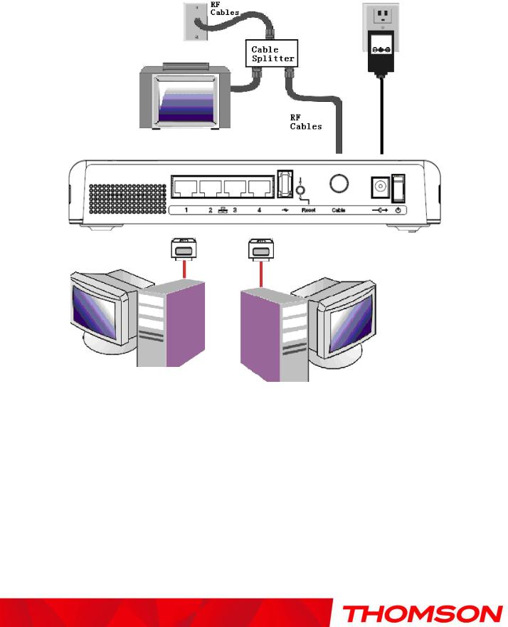
Connecting the Wireless Gateway to a Single Computer
This section of the manual explains how to connect your Wireless Gateway to the Ethernet port on your computer and install the necessary software. Please refer to Figure 1 to help you connect your Digital Cable Modem for the best possible connection.
Attaching the Cable TV Wire to the Wireless Gateway
1.Locate the Cable TV wire. You may find it one of three ways:
a.Connected directly to a TV, a Cable TV converter box, or VCR. The line will be connected to the jack which should be labeled either IN, CABLE IN, CATV, CATV IN, etc.
b.Connected to a wall-mounted cable outlet.
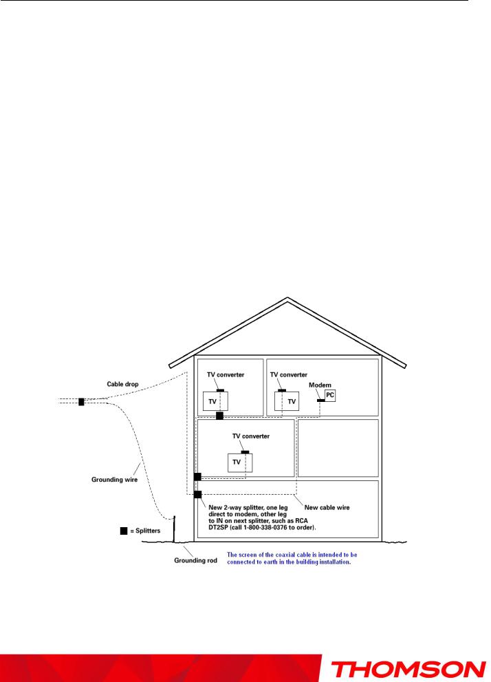
c.Coming out from under a baseboard heater or other location. See Figure 1 for the wiring example.
Notes: For optimum performance, be sure to connect your Wireless Gateway to the first point the cable enters your home. The splitter must be rated for at least 1GHz.
Fig. 1: Basic Home Wiring
10
Illustrations contained in this document are for representation only.
Chapter 1: Connections and Setup
Important Connection Information
The Wireless Gateway supports 4 Ethernet connections simultaneously.
Below are important points to remember before you connect the Wireless Gateway.
Ethernet Connection to a Computer
Make the connection to the modem in the following sequence:
1.Connect one end of the coaxial cable to the cable connection on the wall, and the other end to the CABLE jack on the Wireless Gateway.
2.Connect the plug from the DC power supply into the POWER DC ADAPTER jack on the Cable Wireless Gateway, and plug the power supply into a DC outlet.
Note: Use only the power supply that accompanied this unit. Using other adapters may damage the unit.
3.Connect one end of the Ethernet cable (straight-wired, see below) to the Ethernet port on the back of your computer, and the other end to the ETHERNET port on the Wireless Gateway.
Make sure that the Ethernet cable is straight-wired (not “null” or crossover-wired). However, you will need a crossover-type cable if you are connecting the modem to a hub, or a hub within a port switch that provides the same function.
Fig.2: Ethernet Connection
11
Illustrations contained in this document are for representation only.
Chapter 1: Connections and Setup
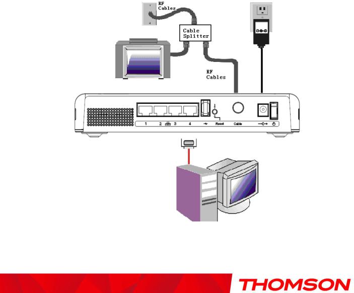
Connecting More Than One Computer to the Wireless Gateway
If you need to connect more than one computer to TCW770, simply connect the computers to the Ethernet ports on the rear panel.
Fig.3: Multiple-PC Connection
Note: You may need to check with your service provider in order to connect multiple computers.
12
Illustrations contained in this document are for representation only.

Chapter 1: Connections and Setup
Turning on the Wireless Gateway
After installing the Wireless Gateway and turn it on for the first time (and each time the modem is reconnected to the power), it goes through several steps before it can be used. Each of these steps is represented by a different pattern of flashing lights on the front of the modem.
Note: All indicators flash once before the initialization sequence.
If all of the lights are flashing sequentially, it means the Wireless Gateway is automatically updating its system software. Please wait for the lights to stop flashing. You cannot use your modem during this time. Do not remove the power supply or reset the Wireless Gateway during this process.
13
Illustrations contained in this document are for representation only.

Chapter 2: WEB Configuration
Chapter 2: WEB Configuration
To make sure that you can access the Internet successfully, please check the following first.
1.Make sure the Ethernet connection between the Wireless Gateway and your computer is OK.
2.Make sure the TCP/IP protocol is set properly.
3.Subscribe to a Cable Company.
Accessing the Web Configuration
The Wireless Gateway offers local management capability through a built in HTTP server and a number of diagnostic and configuration web pages. You can configure the settings on the web page and apply them to the device.
Once your host PC is properly configured; please proceed as follows:
1.Start your web browser and type the private IP address of the Wireless Gateway on the URL field: 192.168.0.1.
2.After connecting to the device, you will be prompted to enter username and password. By default, the username is ― ‖ and the password is ―admin‖.
3.We strongly recommend to change the default password ―admin‖ on the first connection : Please define a username and password for administration .
This message will be display until, it will be not change
Fig. 4
If you login successfully, the main page will appear.
13
Illustrations contained in this document are for representation only.
Chapter 2: WEB Configuration
Outline of Web Manager
The main screen will be shown as below.
Fig. 5
Main Menu: the hyperlinks on the top of the page.
Title: the sidebar on the left side of the page indicates the title of this management interface, e.g., Software in this example
Main Window: the current workspace of the web management, containing configuration or status information
For easy navigation, the pages are organized in groups, with group names main menu, individual page names within each group are provided in the sidebar. To navigate to a page, click the group hyperlink at the top, then the page title on the sidebar.
Your cable company may not support the reporting of some items of information listed on your gateway’s internal web pages. In such cases, the information field appears blank. This is normal.
14
Illustrations contained in this document are for representation only.
Chapter 2: WEB Configuration
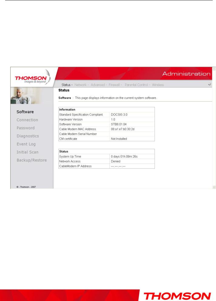
Status
1. Software
The information section shows the hardware and software information about your gateway.
The status section of this page shows how long your gateway has operated since last time being powered up, and some key information the Cable Modem received during the initialization process with your cable company. If Network Access shows ―Allowed,‖ then your cable company has configured your gateway to have Internet connectivity. If not, you may not have Internet access, and should contact your cable company to resolve this.
Fig. 6
15
Illustrations contained in this document are for representation only.
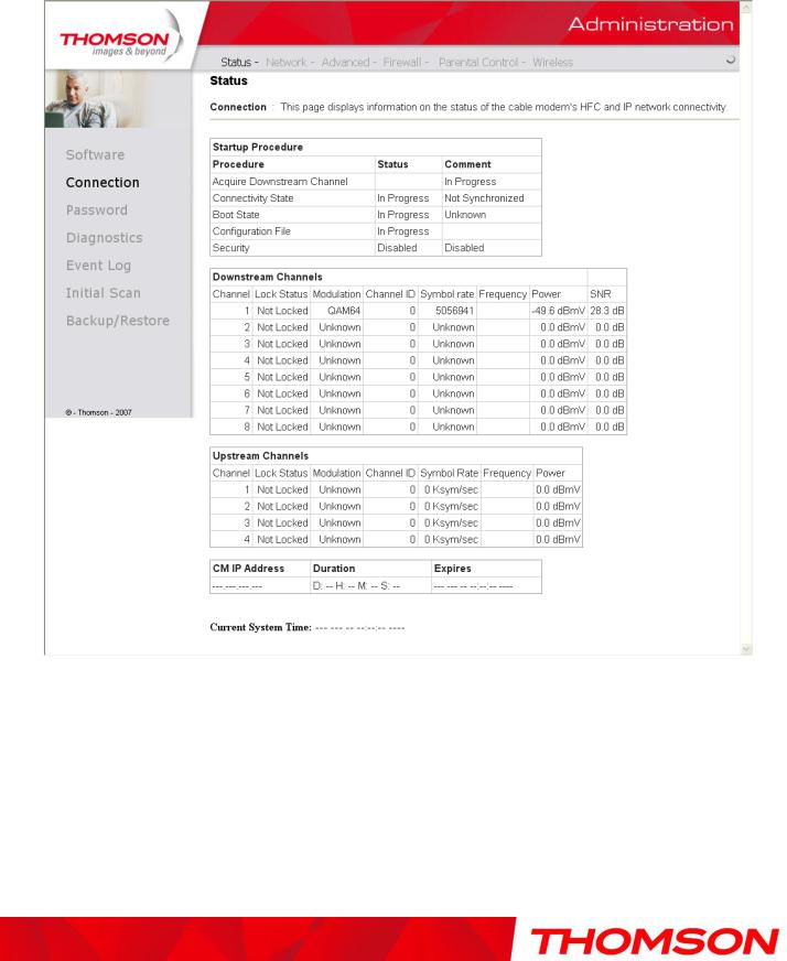
Chapter 2: WEB Configuration
2. Connection
This page reports current connection status containing startup procedures, downstream and upstream status, CM online information, and so on. The information can be useful to your cable company’s support technician if you’re having problems.
Fig. 7
16
Illustrations contained in this document are for representation only.
 Loading...