


TS 840
AUTOMATIC TRANSFER SWITCHES
INSTALLATION, OPERATING &
SERVICE MANUAL
PM057 Rev 8 10/01/25
9087A – 198th Street, Langley, BC Canada V1M 3B1 Ÿ Telephone (604) 888-0110 Telefax (604) 888-3381 Ÿ E-Mail: info@thomsontechnology.com Ÿ www.thomsontechnology.com

TS 840 TRANSFER SWITCH
TABLE OF CONTENTS
1. |
PRODUCT REVISION HISTORY |
1 |
|
2. |
EQUIPMENT STORAGE |
1 |
|
|
2.1. |
ENVIRONMENTAL CONDITIONS |
1 |
3. |
NOTES TO INSTALLER |
2 |
|
|
3.1. UPSTREAM CIRCUIT PROTECTIVE DEVICES/ELECTRICAL CONNECTIONS |
2 |
|
|
3.2. TRANSFER SWITCHES WITH INTEGRAL OVER CURRENT PROTECTION |
3 |
|
|
3.3. SYSTEM PHASING-HIGH LEG DELTA SYSTEMS |
4 |
|
|
3.4. REMOTE START CONTACT FIELD WIRING |
5 |
|
|
3.5. |
DIELECTRIC TESTING |
5 |
|
3.6. INSTALLATION OF OPEN TYPE TRANSFER SWITCHES |
5 |
|
|
3.7. MOUNTING OF ENCLOSED TRANSFER SWITCHES |
5 |
|
4. |
GENERAL DESCRIPTION |
8 |
|
|
4.1. |
PRODUCT MODEL CODE |
10 |
|
4.2. |
TYPICAL COMMISSIONING PROCEDURES |
11 |
5. |
GENERAL THEORY OF OPERATION |
11 |
|
|
5.1. STANDARD AUTOMATIC TRANSFER SWITCH |
11 |
|
|
5.2. SERVICE ENTRANCE AUTOMATIC TRANSFER SWITCH |
12 |
|
|
5.3. |
TEST MODES |
16 |
6. |
OVER CURRENT PROTECTION |
16 |
|
|
6.1. STANDARD TS 840 AUTOMATIC TRANSFER SWITCH |
16 |
|
|
6.2. |
OPTIONAL TS 840 AUTOMATIC TRANSFER SWITCH WITH INTEGRAL OVER |
|
|
|
CURRENT PROTECTION |
16 |
7. |
GENERAL NOTES ON SERVICING TRANSFER SWITCH MECHANISM |
18 |
|
8. |
TRANSFER SWITCH MECHANISM OPERATION– 100A-800A, S STYLE |
20 |
|
PM057 REV 8 10/01/25 |
Thomson Technology |
|
|

TS 840 TRANSFER SWITCH
8.1. MANUAL OPERATION |
20 |
9. RECOMMENDED MAINTENANCE |
22 |
10.FRONT VIEW (TYPICAL) 3 POLE 100A-250A S-STYLE TRANSFER MECHANISM23
11.FRONT VIEW (TYPICAL) 3 POLE 400A-800A S-STYLE TRANSFER MECHANISM
(MECHANISM FRONT COVER REMOVED) |
24 |
|
12. |
FRONT VIEW (TYPICAL) 3 POLE 400A-800A S-STYLE TRANSFER MECHANISM25 |
|
13. |
CABLE TERMINAL INFORMATION |
26 |
14. |
REQUIREMENTS FOR UPSTREAM CIRCUIT PROTECTIVE DEVICES |
26 |
|
14.1. WITHSTAND CURRENT RATINGS (ALL MODELS WITHOUT INTEGRAL |
|
|
OVERCURRENT PROTECTION OPTION) |
26 |
|
14.2. INTERRUPTING CAPACITY CURRENT RATINGS (ALL MODELS WITH INTEGRAL |
|
|
OVERCURRENT PROTECTION OPTION) |
27 |
15. |
GROUND FAULT SITE TEST REQUIREMENTS |
27 |
|
15.1. PERFORMANCE TEST |
27 |
16. |
TROUBLESHOOTING |
29 |
17. |
REPLACEMENT PARTS |
31 |
18. |
PRODUCT RETURN POLICY |
32 |
19. |
NOTES |
33 |
20. |
PERFORMANCE TEST FORM |
34 |
PM057 REV 8 10/01/25 |
Thomson Technology |
|
|

TS 840 TRANSFER SWITCH
1.PRODUCT REVISION HISTORY
The following information provides an historical summary of changes made to this product since
the original release.
Operating & Service Manual Version
Rev 0 02/06/17 |
Original release. |
|
|
Rev 1 04/11/19 |
Change Controller From TSC 800 to TSC 80 Controller. |
|
|
Rev 2 05/03/ 08 |
Changes to incorporate reversing style ATS Motor for 100-250A |
|
transfer switches. |
|
|
Rev 3 05/05/17 |
Revisions to Section 5 and Section 18. |
|
|
Rev 4 06/05/08 |
Revisions to Section 15. |
|
|
Rev 5 07/07/31 |
Changes to Incorporate new S Style 400A mechanism |
|
|
Rev 6 08/01/07 |
Revisions to Appendix A |
|
|
Rev 7 08/03/05 |
Changes to Incorporate new S Style mechanism (100A, 150A, |
|
200A, 250A, 600A, 800A) |
|
|
Rev 8 10/01/25 |
Changes to Incorporate Seismic Certification and Mounting |
|
Requirements |
|
|
Contact Thomson Technology, to obtain applicable instruction manuals or if in doubt about any matter relating to installation, operation or maintenance. Soft copy of the most current version is available at www.thomsontechnology.com.
NOTE: All information contained in this manual is for reference only and is subject
to change without notice.
2.EQUIPMENT STORAGE
The following procedures are required for correct storage of the transfer switch prior to installation.
2.1.ENVIRONMENTAL CONDITIONS
CAUTION!!!
Failure to store and operate equipment under the specified environmental conditions may cause equipment damage and void warranty.
PM057 REV 8 10/01/25 |
1 |
Thomson Technology |

TS 840 TRANSFER SWITCH
2.1.1. EQUIPMENT STORAGE
The transfer switch shall be stored in an environment with a temperature range not exceeding -4° to +158° Fahrenheit (-20° to +70° Celsius) and a humidity range not exceeding 5%-95% non-condensing. Before storing, unpack sufficiently to check for concealed damage. If concealed damage is found, notify the ATS supplier and the Carrier immediately. Repack with the original, or equivalent packing materials. Protect from physical damage. Do not stack. Store indoors in a clean, dry, well ventilated area free of corrosive agents including fumes, salt and concrete/cement dust. Apply heat as necessary to prevent condensation.
2.1.2. EQUIPMENT OPERATING
The transfer switch shall be operated in an environment with a temperature range not exceeding +5° to +122° Fahrenheit (-15° to +50° Celsius) and a humidity range not exceeding 5%-95% non-condensing.
3.NOTES TO INSTALLER
DANGER!!!!
Arc Flash and Shock Hazard. Will cause severe injury or death.
Do not open equipment until ALL power sources are disconnected
This equipment must be installed and serviced only by qualified electrical personnel utilizing safe work practices and appropriate Personal Protective Equipment (PPE). Failure to do so may cause personal injury or death
3.1.UPSTREAM CIRCUIT PROTECTIVE DEVICES/ELECTRICAL CONNECTIONS
To ensure satisfactory installation of this equipment be sure to observe "Cable Terminal Information” regarding power cable connection tightness and "Requirements for Upstream Circuit Protective Devices" located in this manual.
All mechanical and electrical connections must be checked for tightness prior to placing this equipment in service to ensure proper operation and to validate applicable warranty coverage.
PM057 REV 8 10/01/25 |
2 |
Thomson Technology |

TS 840 TRANSFER SWITCH
3.2. TRANSFER SWITCHES WITH INTEGRAL OVER CURRENT PROTECTION
For models of transfer switch with integral over current protection, the over current protection must be set prior to operation. The equipment will be shipped from the factory with a long-time current setting of 100% (of the equipment rating) and maximum shorttime/instantaneous current and time delay settings.
WARNING!
Do Not Energize this equipment until device settings have been verified to ensure proper system protection & coordination. Failure to do so may result in equipment failure.
Refer to Section 5.2.2 of this manual for additional information on operation of the Transfer switch following an over current trip condition.
Refer to information supplied with the transfer switch documentation package for adjustment procedures on the power switching units over current protection trip unit. Contact the factory if any additional information is required.
PM057 REV 8 10/01/25 |
3 |
Thomson Technology |
TS 840 TRANSFER SWITCH
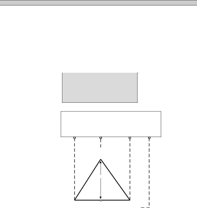
3.3.SYSTEM PHASING-HIGH LEG DELTA SYSTEMS
For systems using high leg delta 240V 3 phase 4 wire systems, connection of supply conductors must have the correct phasing as shown below.
WARNING
Failure to match correct system phasing will result in serious damage to the TSC 80 controller.
Automatic Transfer
Switch (Utility Supply)
PH A |
PH B |
PH C |
Neural |
(UA) |
(UB) |
(UC) |
(N) |
B
(Orange)
(High Leg)
240V |
208V |
240V |
A |
120V |
|
|
|
|
120V |
|
|
|
|
|
C |
||||
|
||||||||||||||||
(Red) |
|
|
|
|
|
|
|
|
|
|
|
|
|
(Yellow) |
||
|
|
|
|
|
|
|
|
|
|
|
|
|
|
|
|
|
N
(White)
Where transfer switches are supplied without power isolation transformers (PT1 & PT2) for ATS control logic it is essential that the orientation of phase conductors of
PM057 REV 8 10/01/25 |
4 |
Thomson Technology |

TS 840 TRANSFER SWITCH
the supply source be arranged such that the phase of highest potential with respect to ground is not connected to the power supply inputs to the controller (A Phase for both supplies). Failure to do so will result in equipment damage.
Per NEC Article 384-3 (f) “The B phase shall be that phase having the higher voltage to ground on a 3-phase, 4-wire delta connected systems.”
3.4.REMOTE START CONTACT FIELD WIRING
As a minimum, the remote engine start control field wiring shall conform to the local regulatory authority on electrical installations. Field wiring of a remote start contact from a transfer switch to a control panel should conform to the following guidelines to avoid possible controller malfunction and/or damage.
3.5.1.Minimum #14 AWG (2.5mm2) wire size shall be used for distances up to 100ft (30m)1). For distances exceeding 100 ft. (30m) consult Thomson Technology
3.5.2.Remote start contact wires should be run in a separate conduit.
3.5.3.Avoid wiring near AC power cables to prevent pick-up of induced voltages.
3.5.4.An interposing relay may be required if field-wiring distance is excessively long (i.e. greater than 100 feet (30m)) and/or if a remote contact has a resistance of greater than 5.0 ohms.
3.5.5.The remote start contact must be voltage free (i.e. dry contact). The use of a “powered” contact will damage the transfer controller.
3.5.DIELECTRIC TESTING
Do not perform any high voltage dielectric testing on the transfer switch with the TSC 80 controller connected into the circuit as serious damage will occur to the controller. All AC control fuses and control circuit isolation plugs connected to the TSC 80 must be removed if high voltage dielectric testing is performed on the transfer switch.
3.6.INSTALLATION OF OPEN TYPE TRANSFER SWITCHES
Please refer to the factory for additional information.
3.7.MOUNTING OF ENCLOSED TRANSFER SWITCHES
Model TS840, TS870 and TS880 Automatic Transfer Switches and Automatic Transfer and Bypass Isolation Switches in "standard" enclosures are seismic certified under AC156 building code for non-structural components.
PM057 REV 8 10/01/25 |
5 |
Thomson Technology |

TS 840 TRANSFER SWITCH
"Standard" enclosures are all transfer switch enclosures Thomson Technology offers in NEMA 1, NEMA 2, NEMA 3R and NEMA 4X for the above listed product. If a customer requests a custom enclosure it would not be covered under the generic certificate; if certification were a requirement Consult factory before ordering.
The Automatic Transfer Switches are qualified to the highest known level in North America; based on site class D. Specifically this is a spectral acceleration of 342%. The transfer switch must be installed per the anchoring details provided for seismic qualification. The equipment can be mounted in alternate means and still qualify if a qualified Civil Engineer designs the alternate method of anchoring.
PM057 REV 8 10/01/25 |
6 |
Thomson Technology |
TS 840 TRANSFER SWITCH
Anchoring Notes:
1. Anchoring must be designed according to IBC 2006 or latest version.
PM057 REV 8 10/01/25 |
7 |
Thomson Technology |

TS 840 TRANSFER SWITCH
2.The anchoring details shown are recommended according to the seismic certification; design Engineer may use alternate anchors within the scope of IBC.
3.Wall anchors in concrete; use a typical concrete anchor as necessary.
4.Expansion anchors as shown to be installed according to manufacturer's recommendation.
5.The 800-1200A NEMA 3R ATS enclosure may be floor/wall mounted or it may be free standing (floor mounted only); If free standing it must be a minimum of 12" (305mm) away from pipes, conduits or other obstructions to allow for sway during a seismic event.
4.GENERAL DESCRIPTION
Thomson Technology TS 840 series of Automatic Transfer Switches employ two mechanically interlocked enclosed contact power switching units and a microprocessor based controller to automatically transfer system load to a generator supply in the event of a utility supply failure. System load is then automatically re-transferred back to the utility supply following restoration of the utility power source to within normal operating limits.
The standard TS 840 series Automatic Transfer Switch is rated for 100% system load and requires upstream over current protection. The TS 840 Automatic Transfer Switch may be supplied with optional integral over current protection within the enclosed contact power switching units for applications such as Service Entrance Rated equipment. Refer to Section 6 of this manual for detailed information on over current protection.
The TS 840 series transfer switches use a type TSC 80 microprocessor based controller which provides all necessary control functions for fully automatic operation. The TSC 80 controller is mounted on the door of the transfer switch enclosure and operating status is shown via LED lights. For further information on the TSC 80 Transfer Controller, refer to separate instruction manual PM063.
The power switching devices used for the Utility and Generator sources are operated by an electrically driven motor mechanism in the transfer switch. The transfer switch motor utilizes the power from the source to which the electrical load is being transferred. The mechanism provides a positive mechanical interlock to prevent both power switching units from being closed at the same time, which allows an open transition, “break-before-make” transfer sequence. The TSC 80
PM057 REV 8 10/01/25 |
8 |
Thomson Technology |

TS 840 TRANSFER SWITCH
transfer controller provides a standard neutral position delay timer to allow adequate voltage decay during transfer operation to prevent out of phase transfers.
Note: For the purpose of this manual, the following standard nomenclature is utilized:
∙Utility: to indicate the source of primary power
∙Generator: to indicate the source of standby power
∙Power switching device: to indicate the transfer switch power switching device
PM057 REV 8 10/01/25 |
9 |
Thomson Technology |
 Loading...