Texas Instruments NE5532AP, NE5532P Datasheet

NE5532, NE5532A, NE5532I, NE5532AI DUAL LOW-NOISE OPERATIONAL AMPLIFIERS
SLOS075A ± NOVEMBER 1979 ± REVISED SEPTEMBER 1990
DEquivalent Input Noise Voltage 5 nv/√ Hz Typ at 1 kHz
DUnity-Gain Bandwidth . . . 10 MHz Typ
DCommon-Mode Rejection Ratio
100 dB Typ
DHigh DC Voltage Gain . . . 100 V/mV Typ
DPeak-to-Peak Output Voltage Swing
32 V Typ With VCC ± = ±18 V and RL = 600 Ω
DHigh Slew Rate . . . 9 V/μs Typ
DWide Supply Voltage Range . . . ± 3 V to ± 20 V
P PACKAGE (TOP VIEW)
OUT |
|
1 |
8 |
|
VCC+ |
|
|
||||
|
|
|
|
||
IN ± |
|
2 |
7 |
|
OUT |
IN+ |
|
3 |
6 |
|
IN ± |
|
|
||||
VCC ± |
|
4 |
5 |
|
IN+ |
|
|
||||
|
|
|
|
|
|
|
|
|
|
|
|
DDesigned to Be Interchangeable With Signetics NE5532 and NE5532A
description
The NE5532 and NE5532A are monolithic high-performance operational amplifiers combining excellent dc and ac characteristics. They feature very low noise, high output drive capability, high unity-gain and maximum-output-swing bandwidths, low distortion, high slew rate, input-protection diodes, and output short-circuit protection. These operational amplifiers are internally compensated for unity-gain operation. The NE5532A has specified maximum limits for equivalent input noise voltage.
The NE5532 and NE5532A are characterized for operation from 0°C to 70°C. The NE5532I and NE5532AI are characterized for operation from ±40°C to 85°C.
symbol (each amplifier)
|
IN+ |
|
+ |
|
OUT |
|
|
||||
|
|
|
± |
|
|
|
|
|
|
||
|
|
|
|
|
|
|
IN ± |
|
|
|
|
|
|
|
PRODUCTION DATA information is current as of publication date. Products conform to specifications per the terms of Texas Instruments standard warranty. Production processing does not necessarily include testing of all parameters.
Copyright 1990, Texas Instruments Incorporated
POST OFFICE BOX 655303 •DALLAS, TEXAS 75265 |
1 |

NE5532, NE5532A, NE5532I, NE5532AI
DUAL LOW-NOISE OPERATIONAL AMPLIFIERS
SLOS075A ± NOVEMBER 1979 ± REVISED SEPTEMBER 1990
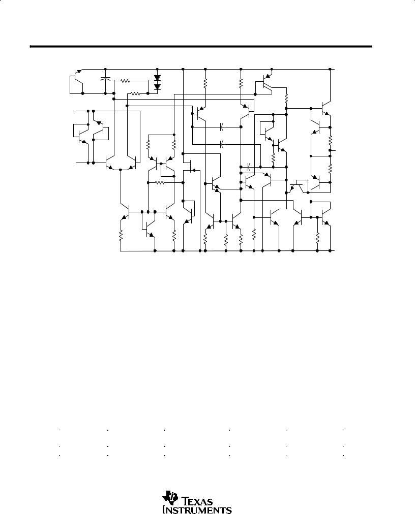
schematic (each amplifier)
VCC+ |
36 pF |
IN+ |
37 pF |
14 pF |
15 Ω |
OUT |
7 pF |
IN ± |
15 Ω |
460 Ω |
VCC± |
Component values shown are nominal.
absolute maximum ratings over operating free-air temperature range (unless otherwise noted)
Supply voltage, VCC+ (see Note 1) . . . . . . . . . . . . . . . . . . . . . . . . . . . . . . . . . . . . . . |
. . . . . . . . . . . . . . . . . . . . . 22 V |
Supply voltage, VCC ± (see Note 1) . . . . . . . . . . . . . . . . . . . . . . . . . . . . . . . . . . . . . . |
. . . . . . . . . . . . . . . . . . . . ±22 V |
Input voltage, either input (see Notes 1 and 2) . . . . . . . . . . . . . . . . . . . . . . . . . . . . |
. . . . . . . . . . . . . . . . . . . . VCC± |
Input current (see Note 3) . . . . . . . . . . . . . . . . . . . . . . . . . . . . . . . . . . . . . . . . . . . . . . |
. . . . . . . . . . . . . . . . . . ± 10 mA |
Duration of output short circuit (see Note 4) . . . . . . . . . . . . . . . . . . . . . . . . . . . . . . |
. . . . . . . . . . . . . . . . . unlimited |
Continuous total power dissipation . . . . . . . . . . . . . . . . . . . . . . . . . . . . . . . . . . . . . |
See Dissipation Rating Table |
Operating free-air temperature range: NE5532, NE5532A . . . . . . . . . . . . . . . . . |
. . . . . . . . . . . . . . 0°C to 70°C |
NE5532I, NE5532AI . . . . . . . . . . . . . . . . |
. . . . . . . . . . . . ±40°C to 85°C |
Storage temperature range . . . . . . . . . . . . . . . . . . . . . . . . . . . . . . . . . . . . . . . . . . . . . |
. . . . . . . . . . . ±65°C to 150°C |
Lead temperature 1,6 mm (1/16 inch) from case for 10 seconds . . . . . . . . . . . . |
. . . . . . . . . . . . . . . . . . . 260°C |
NOTES: 1. All voltage values, except differential voltages, are with respect to the midpoint between VCC+ and VCC±.
2.The magnitude of the input voltage must never exceed the magnitude of the supply voltage.
3.Excessive input current will flow if a differential input voltage in excess of approximately 0.6 V is applied between the inputs unless some limiting resistance is used.
4.The output may be shorted to ground or either power supply. Temperature and/or supply voltages must be limited to ensure the maximum dissipation rating is not exceeded.
DISSIPATION RATING TABLE
|
PACKAGE |
TA ≤ 25°C |
OPERATING FACTOR |
TA = 70°C |
TA = 85°C |
|
|
POWER RATING |
ABOVE TA = 25°C |
POWER RATING |
POWER RATING |
|
|
|
|
|
||||
|
P |
1000 mW |
8 mW/°C |
640 mW |
520 mW |
|
|
|
|
|
|
|
|
|
|
|
|
|
|
|
|
|
|
|
|
|
|
2 |
POST OFFICE BOX 655303 •DALLAS, TEXAS 75265 |
 Loading...