


 Loading...
|
bq24072, bq24073 |
|
bq24074, bq24075 |
www.ti.com |
SLUS810–SEPTEMBER 2008 |
1.2A USB-FRIENDLY Li-Ion BATTERY CHARGER AND POWER-PATH MANAGEMENT IC
FEATURES
∙28V Input Rating
∙Integrated Dynamic Power Management Feature
∙Supports up to 1.5A Output Current
∙Integrated USB Charge Control With Selectable 100 mA and 500 mA Maximum Input Current
∙Programmable Pre-Charge and Fast-Charge Safety Timers
∙Thermal Regulation for Charge Control
∙Reverse Current, Short-Circuit and Thermal Protection
∙NTC Thermistor Input
∙Soft-Start Feature to Reduce Inrush Current
∙Status Indication – Charging/Done, Power Good
∙Small 3 mm × 3 mm 16 Lead QFN Package
APPLICATIONS
∙Smart Phones
∙PDAs
∙MP3 Players
∙Low-Power Handheld Devices
DESCRIPTION
The bq2407x series of devices are highly integrated Li-ion linear chargers and system power path management devices targeted at space-limited portable applications. The devices operate from either a USB port or AC adapter. The high input voltage range with input overvoltage protection supports low-cost unregulated adapters.
The bq2407x powers the system while simultaneously and independently charging the battery. This feature reduces the number of charge and discharge cycles on the battery, allows for proper charge termination and enables the system to run with a defective or absent battery pack. Additionally, this enables instant system turn-on even with a totally discharged battery. The power-path management architecture also permits the battery to supplement the system current requirements when the adapter cannot deliver the peak system currents, enabling the use of a smaller adapter.
The battery is charged in three phases: conditioning, constant current, and constant voltage. In all charge phases, an internal control loop monitors the IC junction temperature and reduces the charge current if the internal temperature threshold is exceeded.
TYPICAL APPLICATION CIRCUIT
SYSTEM
Adaptor |
|
PGOOD |
CHG |
|
|
|
|
|
|
DC+ |
|
IN |
|
OUT |
|
|
|
|
|
GND |
|
|
|
|
|
|
VSS |
|
|
|
|
TS |
|
|
|
|
|
|
EN2 |
|
|
BAT |
|
EN1 |
|
|
|
|
|
|
PACK+ |
|
|
TMR |
|
|
|
|
|
|
TEMP |
|
|
|
|
|
|
|
CE |
|
|
bq24074 |
|
|
|
PACK- |
ITERM |
ILIM |
ISET |
|
|
|||
Please be aware that an important notice concerning availability, standard warranty, and use in critical applications of Texas Instruments semiconductor products and disclaimers thereto appears at the end of this data sheet.
PRODUCTION DATA information is current as of publication date. |
Copyright © 2008, Texas Instruments Incorporated |
Products conform to specifications per the terms of the Texas |
|
Instruments standard warranty. Production processing does not |
|
necessarily include testing of all parameters. |
|
bq24072, bq24073 bq24074, bq24075
SLUS810–SEPTEMBER 2008 |
www.ti.com |
These devices have limited built-in ESD protection. The leads should be shorted together or the device placed in conductive foam during storage or handling to prevent electrostatic damage to the MOS gates.
DESCRIPTION (CONTINUED)
The charger power stage and charge current sense functions are fully integrated. The charger function has high accuracy current and voltage regulation loops, charge status display, and charge termination. The input current limit and charge current are programmable using external resistors.
ORDERING INFORMATION
PART NUMBER |
VOVP |
VOUT(REG) |
VDPM |
OPTIONAL |
MARKING |
(1)(2) |
|
|
|
FUNCTION |
|
bq24072RGTR |
6.6 V |
VBAT + 200 mV |
VO(REG) – 100 mV |
TD |
CKP |
bq24072RGTT |
6.6 V |
VBAT + 200 mV |
VO(REG) – 100 mV |
TD |
CKP |
bq24073RGTR |
6.6 V |
4.4 V |
VO(REG) – 100 mV |
TD |
CKQ |
bq24073RGTT |
6.6 V |
4.4 V |
VO(REG) – 100 mV |
TD |
CKQ |
bq24074RGTR |
10.5 V |
4.4 V |
VO(REG) – 100 mV |
ITERM |
BZF |
bq24074RGTT |
10.5 V |
4.4 V |
VO(REG) – 100 mV |
ITERM |
BZF |
bq24075RGTR |
6.6 V |
5.5 V |
4.3 V |
SYSOFF |
CDU |
bq24075RGTT |
6.6 V |
5.5 V |
4.3 V |
SYSOFF |
CDU |
(1)The RGT package is available in the following options:
R - taped and reeled in quantities of 3,000 devices per reel. T - taped and reeled in quantities of 250 devices per reel.
(2)This product is RoHS compatible, including a lead concentration that does not exceed 0.1% of total product weight, and is suitable for use in specified lead-free soldering processes. In addition, this product uses package materials that do not contain halogens, including bromine (Br) or antimony (Sb) above 0.1% of total product weight.
ABSOLUTE MAXIMUM RATINGS(1)
over operating free-air temperature range (unless otherwise noted)
VI |
Input Voltage |
II |
Input Current |
IO |
Output Current (Continuous) |
|
Output Sink Current |
TJ |
Junction temperature |
Tstg |
Storage temperature |
|
VALUE |
UNIT |
|
IN (with respect to VSS) |
–0.3 to 28 |
V |
|
BAT (with respect to VSS) |
–0.3 to 5 |
V |
|
OUT, EN1, EN2, CE, TS, ISET, PGOOD, CHG, ILIM, TMR, |
–0.3 to 7 |
V |
|
ITERM, SYSOFF, TD (with respect to VSS) |
|||
|
|
||
IN |
1.6 |
A |
|
OUT |
5 |
A |
|
BAT (Discharge mode) |
5 |
A |
|
CHG, PGOOD |
15 |
mA |
|
|
–40 to 150 |
°C |
|
|
–65 to 150 |
°C |
(1)Stresses beyond those listed under absolute maximum ratings may cause permanent damage to the device. These are stress ratings only, and functional operation of the device at these or any other conditions beyond those indicated under recommended operating conditions is not implied. Exposure to absolute-maximum-rated conditions for extended periods may affect device reliability. All voltage values are with respect to the network ground terminal unless otherwise noted.
DISSIPATION RATINGS(1)
PACKAGE(2) |
RθJA |
RθJC |
TA ≤ 25°C |
DERATING FACTOR |
|
|
|
POWER RATING |
TA > 25°C |
RGT (1) |
39.47 °C/W |
2.4 °C/W |
2.3 W |
34.6 mW/°C |
(1)This data is based on using the JEDEC High-K board and the exposed die pad is connected to a Cu pad on the board. The pad is connected to the ground plane by a 2x3 via matrix.
(2)For the most current package and ordering information, see the Package Option Addendum at the end of this document, or see the TI website at www.ti.com.
2 |
Submit Documentation Feedback |
Copyright © 2008, Texas Instruments Incorporated |
Product Folder Link(s): bq24072 bq24073 bq24074 bq24075

bq24072, bq24073 bq24074, bq24075
www.ti.com SLUS810–SEPTEMBER 2008
RECOMMENDED OPERATING CONDITIONS
|
|
MIN |
MAX |
UNIT |
|
IN voltage range |
4.35 |
26 |
V |
VI |
’72, ’73, ‘75 |
4.35 |
6.6 |
V |
|
IN operating voltage range |
4.35 |
10.5 |
|
|
‘74 |
|
||
IIN |
Input current, IN pin |
|
1.5 |
A |
IOUT |
Current, OUT pin |
|
4.5 |
A |
IBAT |
Current, BAT pin (Discharging) |
|
4.5 |
A |
ICHG |
Current, BAT pin (Charging) |
|
1.2 |
A |
TJ |
Junction Temperature |
–40 |
125 |
°C |
RILIM |
Maximum input current programming resistor |
1100 |
8000 |
Ω |
RISET |
Fast-charge current programming resistor |
750 |
3000 |
Ω |
RITERM |
Termination current programming resistor |
0 |
15 |
kΩ |
RTMR |
Timer programming resistor |
18 |
72 |
kΩ |
ELECTRICAL CHARACTERISTICS
Over junction temperature range (0° ≤ TJ ≤ 125°C) and the recommended supply voltage range (unless otherwise noted)
PARAMETER |
TEST CONDITIONS |
MIN |
TYP |
MAX UNIT |
INPUT
 UVLO
UVLO
Vhys
VIN(DT)
Vhys
tDGL(PGOOD)
VOVP
Vhys
tBLK
tREC
Undervoltage lock-out |
VIN: 0 V → 4 V |
|
3.2 |
3.3 |
3.4 |
V |
Hysteresis on UVLO |
VIN: 4 V → 0 V |
|
200 |
|
300 |
mV |
Input power detection threshold |
Input power detected when VIN > VBAT |
+ VIN(DT) |
55 |
80 |
130 |
mV |
VBAT = 3.6 V, VIN: 3.5 V → 4 V |
|
|||||
|
|
|
|
|
|
|
Hysteresis on VIN(DT) |
VBAT = 3.6 V, VIN: 4 V → 3.5 V |
|
20 |
|
|
mV |
Deglitch time, input power detected |
Time measured from VIN: 0 V → 5 V 1 μs |
|
4 |
|
ms |
|
status |
rise-time to PGOOD = LO |
|
|
|
||
|
|
|
|
|
||
Input overvoltage protection threshold |
(’72, ’73, ’75) VIN: 5 V → 7 V |
|
6.4 |
6.6 |
6.8 |
V |
(’74) VIN: 5 V → 11 V |
|
10.2 |
10.5 |
10.8 |
||
|
|
|
||||
Hysteresis on OVP |
(’72, ’73, ’75) VIN: 7 V → 5V |
|
|
110 |
|
mV |
|
(’74) VIN: 11 V → 5 V |
|
|
175 |
|
|
Input overvoltage blanking time |
|
|
|
50 |
|
μs |
Input overvoltage recovery time |
Time measured from VIN: 11 V → 5 V with 1 μs |
|
2 |
|
ms |
|
fall-time to PGOOD = LO |
|
|
|
|||
|
|
|
|
|
|
|
ILIM, TEST ISET SHORT CIRCUIT
ISC |
Current source |
VSC
 QUIESCENT CURRENT
IBAT(PDWN)
 IIN
IIN
ICC
 POWER PATH
VDO(IN-OUT)
VDO(BAT-OUT)
VO(REG)
|
CE = LO or HI, input power not detected, No |
|
Sleep current into BAT pin |
load on OUT pin, |
|
|
TJ = 85°C |
|
Standby current into IN pin |
EN1= HI, EN2=HI, VIN = 6 V, TJ=85°C |
|
EN1= HI, EN2=HI, VIN = 10 V, TJ=85°C |
||
|
||
Active supply current, IN pin |
CE = LO, VIN = 6 V, no load on OUT pin, |
|
VBAT > VBAT(REG), (EN1, EN2) ≠ (HI, HI) |
||
|
||
VIN – VOUT |
VIN = 4.3 V, IIN = 1A, VBAT = 4.2V |
|
VBAT – VOUT |
IOUT = 1 A, VIN = 0 V, VBAT > 3 V |
|
|
VIN > VOUT + VDO(IN-OUT), VBAT < 3.2 V |
|
OUT pin voltage regulation (bq24072) |
VIN > VOUT + VDO(IN-OUT), VBAT ≥ 3.2 V |
|
|
||
OUT pin voltage regulation (bq24073, |
VIN > VOUT + VDO(IN-OUT) |
|
bq24074) |
|
|
OUT pin voltage regulation (bq24075) |
VIN > VOUT + VDO(IN-OUT) |
1.3mA
520 mV
mV
6.5μA
|
|
50 |
μA |
|
|
200 |
|
|
|
1.5 |
mA |
|
300 |
475 |
mV |
|
50 |
100 |
mV |
|
3.4 |
|
|
|
VBAT + |
|
|
|
225mV |
|
V |
|
|
|
|
4.3 |
4.4 |
4.5 |
|
5.4 |
5.5 |
5.6 |
|
Copyright © 2008, Texas Instruments Incorporated |
Submit Documentation Feedback |
3 |
Product Folder Link(s): bq24072 bq24073 bq24074 bq24075

bq24072, bq24073 bq24074, bq24075
SLUS810–SEPTEMBER 2008 |
www.ti.com |
ELECTRICAL CHARACTERISTICS (continued)
Over junction temperature range (0° ≤ TJ ≤ 125°C) and the recommended supply voltage range (unless otherwise noted)
 IINmax
KILIM
IINmax
VIN(LOW)
VDPM
VBSUP1
VBSUP2
VO(SC1)
VO(SC2)
PARAMETER
Maximum input current
Maximum input current factor
Programmable input current limit range
Input voltage threshold when input current is reduced
Output voltage threshold when charging current is reduced
Enter battery supplement mode
Exit battery supplement mode
Output short-circuit detection threshold, power-on
Output short-circuit detection threshold, supplement mode VBAT – VOUT > VO(SC2) indicates short-circuit
TEST CONDITIONS |
MIN |
TYP |
MAX |
UNIT |
|
EN1 = LO, EN2 = LO |
90 |
95 |
100 |
mA |
|
EN1 = HI, EN2 = LO |
450 |
475 |
500 |
||
|
|||||
EN2 = HI, EN1 = LO |
|
KILIM/RILIM |
|
A |
|
ILIM ≥ 500mA |
1480 |
1550 |
1620 |
AΩ |
|
200mA < ILIM < 500mA |
1320 |
1470 |
1620 |
|
|
EN2 = HI, EN1 = LO, RILIM = 8 kΩ to 1.1 kΩ |
200 |
|
1500 |
mA |
|
EN2 = LO, EN1 = X |
4.35 |
4.5 |
4.63 |
V |
|
(’72, ’73, ’74) |
|
VO(REG) – |
|
V |
|
|
|
100mV |
|
||
|
|
|
|
||
(’75) |
|
4.3 |
|
V |
|
|
|
VOUT ≤ VBAT |
|
mV |
|
|
|
–40 |
|
||
|
|
|
|
||
|
|
VOUT ≥ |
|
mV |
|
|
|
VBAT–20 |
|
||
|
|
|
|
||
|
0.8 |
0.9 |
1 |
V |
|
|
200 |
250 |
300 |
mV |
tDGL(SC2) |
Deglitch time, supplement mode short |
|
circuit |
||
|
||
tREC(SC2) |
Recovery time, supplement mode |
|
short circuit |
||
|
||
BATTERY CHARGER |
||
IBAT
VBAT
VBAT(REG)
VLOWV
tDGL1(LOWV)
tDGL2(LOWV)
ICHG
Source current for BAT pin short-circuit detection
BAT pin short-circuit detection threshold
 Battery charge voltage
Pre-charge to fast-charge transition threshold
Deglitch time on pre-charge to fast-charge transition
Deglitch time on fast-charge to pre-charge transition
Battery fast charge current range
Battery fast charge current
VBAT(REG) > VBAT > VLOWV, VIN = 5 V CE = LO, EN1 = LO, EN2 = HI
CE = LO, EN1= LO, EN2 = HI,
VBAT > VLOWV, VIN = 5 V, IINmax > ICHG, no load on OUT pin, thermal loop and DPM loop not
active
KISET |
Fast charge current factor |
|
IPRECHG |
Pre-charge current |
|
KPRECHG |
Pre-charge current factor |
|
ITERM |
Termination comparator detection |
|
threshold (internally set) |
||
|
CE = LO, (EN1, EN2) ≠ (LO, LO),
VBAT > VRCH, t < tMAXCH, VIN = 5 V, DPM loop and thermal loop not active
CE = LO, (EN1, EN2) = (LO, LO),
VBAT > VRCH, t < tMAXCH, VIN = 5 V, DPM loop and thermal loop not active
|
250 |
|
μs |
|
60 |
|
ms |
4 |
7.5 |
11 |
mA |
1.6 |
1.8 |
2.0 |
V |
4.16 |
4.20 |
4.24 |
V |
2.9 |
3 |
3.1 |
V |
|
25 |
|
ms |
|
25 |
|
ms |
300 |
|
1200 |
mA |
|
KISET/RISET |
|
A |
797 |
890 |
975 |
AΩ |
|
KPRECHG/RISET |
|
A |
70 |
88 |
106 |
AΩ |
0.09×ICHG |
0.1×ICHG |
0.11×ICHG |
A |
|
|||
0.027×ICHG |
0.033×ICHG |
0.040×ICHG |
|
IBIAS(ITERM) |
Current for external |
72 |
75 |
78 |
μA |
|
termination-setting resistor |
||||||
|
|
|
|
|
||
ITERM |
Termination current threshold |
KITERM × RITERM / RISET |
|
A |
||
(externally set) (bq24074) |
|
|
||||
|
|
|
|
|
||
4 |
Submit Documentation Feedback |
Copyright © 2008, Texas Instruments Incorporated |
Product Folder Link(s): bq24072 bq24073 bq24074 bq24075

|
bq24072, bq24073 |
|
bq24074, bq24075 |
www.ti.com |
SLUS810–SEPTEMBER 2008 |
ELECTRICAL CHARACTERISTICS (continued)
Over junction temperature range (0° ≤ TJ ≤ 125°C) and the recommended supply voltage range (unless otherwise noted)
KITERM
tDGL(TERM)
VRCH
tDGL(RCH)
tDGL(NO-IN)
IBAT(DET)
tDET
PARAMETER
K Factor for termination detection threshold (externally set) (bq24074)
 Deglitch time, termination detected
Recharge detection threshold
Deglitch time, recharge threshold detected
Delay time, input power loss to charger turn-off
 Sink current for battery detection Battery detection timer
BATTERY CHARGING TIMERS
tPRECHG |
Pre-charge safety timer value |
tMAXCHG |
Charge safety timer value |
tPRECHG |
Pre-charge safety timer value |
tMAXCHG |
Charge safety timer value |
KTMR |
Timer factor |
 BATTERY-PACK NTC MONITOR(1)
INTC
VHOT
VHYS(HOT)
VCOLD
VHYS(COLD)
tDGL(TS)
VDIS(TS)
 NTC bias current
High temperature trip point
 Hysteresis on high trip point
Low temperature trip point
 Hysteresis on low trip point
Deglitch time, pack temperature fault detection
TS function disable threshold (bq24072, bq24073)
 THERMAL REGULATION
TJ(REG) |
Temperature regulation limit |
TJ(OFF) |
Thermal shutdown temperature |
TJ(OFF-HYS) |
Thermal shutdown hysteresis |
LOGIC LEVELS ON EN1, EN2, CE, SYSOFF, TD
VIL |
Logic LOW input voltage |
VIH |
Logic HIGH input voltage |
IIL |
|
IIH |
|
LOGIC LEVELS ON PGOOD, CHG
TEST CONDITIONS |
MIN |
TYP |
MAX |
UNIT |
CE = LO, (EN1, EN2) ≠ (LO, LO), |
0.008 |
0.0100 |
0.012 |
A |
VBAT > VRCH, t < tMAXCH, VIN = 5 V, DPM loop |
|
|||
and thermal loop not active |
|
|
|
|
CE = LO, (EN1, EN2) = (LO, LO), |
0.0225 |
0.0300 |
0.0375 |
|
VBAT > VRCH, t < tMAXCH, VIN = 5 V, DPM loop |
|
|||
and thermal loop not active |
|
|
|
|
|
0 |
25 |
|
ms |
|
VBAT(REG) |
VBAT(REG) |
VBAT(REG) |
mV |
|
–140 |
–100 |
–60 |
|
|
|
|||
|
|
62.5 |
|
ms |
VBAT = 3.6 V. Time measured from |
|
20 |
|
ms |
VIN: 5 V → 3 V 1 μs fall-time |
|
|
||
|
|
|
|
|
|
5 |
7.5 |
10 |
mA |
|
|
250 |
|
ms |
TMR = floating |
1440 |
1800 |
2160 |
s |
TMR = floating |
14400 |
18000 |
21600 |
s |
18 kΩ < RTMR < 72 kΩ |
|
RTMR × KTMR |
|
s |
18 kΩ < RTMR < 72 kΩ |
10×RTMR ×KTMR |
|
s |
|
|
36 |
48 |
60 |
s/kΩ |
|
72 |
75 |
78 |
μA |
Battery charging |
270 |
300 |
330 |
mV |
Battery charging |
|
30 |
|
mV |
Battery charging |
2000 |
2100 |
2200 |
mV |
Battery charging |
|
300 |
|
mV |
Battery charging |
|
50 |
|
ms |
|
|
VIN - 200mV |
|
V |
|
|
125 |
|
°C |
|
|
155 |
|
°C |
|
|
20 |
|
°C |
|
0 |
|
0.4 |
V |
|
1.4 |
|
6 |
V |
VIL= 0V |
|
|
1 |
μA |
VIH= 1.4V |
|
|
10 |
μA |
VOL |
Output LOW voltage |
ISINK = 5 mA |
0.4 V |
(1)These numbers set trip points of 0°C and 50°C while charging, with 3°C hysteresis on the trip points, with a Vishay Type 2 curve NTC with an R25 of 10 kΩ.
Copyright © 2008, Texas Instruments Incorporated |
Submit Documentation Feedback |
5 |
Product Folder Link(s): bq24072 bq24073 bq24074 bq24075
bq24072, bq24073 bq24074, bq24075
SLUS810–SEPTEMBER 2008 www.ti.com
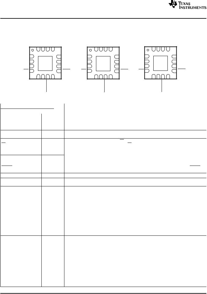
RGT PACKAGE
(Top View)
|
ISET |
TD |
TMR |
IN |
|
|
|
ISET |
ITERM |
TMR |
IN |
|
|
|
ISET |
SYSOFF |
TMR |
IN |
|
|
16 |
15 |
14 |
13 |
|
|
|
16 |
15 |
14 |
13 |
|
|
|
16 |
15 |
14 |
13 |
|
TS |
1 |
|
|
12 |
ILIM |
TS |
1 |
|
|
|
12 |
ILIM |
TS |
1 |
|
|
|
12 |
ILIM |
BAT |
2 |
bq24072 |
11 |
OUT |
BAT |
2 |
|
bq24074 |
11 |
OUT |
BAT |
2 |
|
bq24075 |
11 |
OUT |
|||
|
|
bq24073 |
|
|
|
|
|
|
|
|
|
|
|
|
|||||
BAT |
3 |
10 |
OUT |
BAT |
3 |
|
10 |
OUT |
BAT |
3 |
|
|
|
10 |
OUT |
||||
|
|
|
|
|
|
|
|
||||||||||||
CE |
4 |
|
|
9 |
CHG |
CE |
4 |
|
|
|
9 |
CHG |
CE |
4 |
|
|
|
9 |
CHG |
|
5 |
6 |
7 |
8 |
|
|
|
5 |
6 |
7 |
8 |
|
|
|
5 |
6 |
7 |
8 |
|
|
EN2 |
EN1 |
PGOOD |
VSS |
|
|
|
EN2 |
EN1 |
PGOOD |
VSS |
|
|
|
EN2 |
EN1 |
PGOOD |
VSS |
|
|
|
|
|
|
TERMINAL FUNCTIONS |
|
|
TERMINAL |
|
|
|
||
NAME |
|
NO. |
|
I/O |
DESCRIPTION |
|
'72, '73 |
'74 |
'75 |
|
|
||
|
|
|
||||
|
|
|
|
|
External NTC Thermistor Input. Connect the TS input to the NTC thermistor in the battery pack. TS moniitors |
|
TS |
1 |
1 |
1 |
I |
a 10kΩ NTC thermistor.To disable the external temperature sense circuitry, connect a 10kΩ resistor from TS |
|
|
|
|
|
|
to VSS. |
|
BAT |
2, 3 |
2, 3 |
2, 3 |
I/O |
Charger Power Stage Output and Battery Voltage Sense Input. Connect BAT to the positive terminal of the |
|
battery. Bypass BAT to VSS with a 4.7 μF to 47 μF ceramic capacitor. |
||||||
|
|
|
|
|
||
|
|
|
|
|
Charge Enable Active-Low Input. Connect CE to a high logic level to place the battery charger in standby |
|
CE |
4 |
4 |
4 |
I |
mode. In standby mode, OUT is active. Connect CE to a low logic level to enable the battery charger. CE is |
|
|
|
|
|
|
internally pulled down with ~285 kΩ. |
|
EN2 |
5 |
5 |
5 |
I |
Input Current Limit Configuration Inputs. Use EN1 and EN2 control the maximum input current and enable |
|
EN1 |
6 |
6 |
6 |
I |
USB compliance. See Table 2 for the description of the operation states. EN1 and EN2 are internally pulled |
|
down with ~285 kΩ. |
||||||
|
|
|
|
|
Open-drain Power Good Status Indication Output. PGOOD pulls to VSS when a valid input source is |
|
PGOOD |
7 |
7 |
7 |
O |
detected. PGOOD is high-impedance when the input power is not within specified limits. Connect PGOOD to |
|
|
|
|
|
|
the desired logic voltage rail using a 10kΩ-100kΩ resistor. |
|
VSS |
8 |
8 |
8 |
– |
Ground. Connect to the thermal pad and to the ground rail of the circuit. |
|
CHG |
9 |
9 |
9 |
O |
Open-Drain Charging Status Indication Output. CHG pulls to VSS when the battery is charging. CHG is high |
|
impedance when charging is complete and when charger is disabled. |
||||||
|
|
|
|
|
||
|
|
|
|
|
System Supply Output. OUT provides a regulated output when the input is below the OVP threshold and |
|
OUT |
10, 11 |
10, 11 |
10, 11 |
O |
above the regulation voltage. Connect OUT to the system load. Bypass OUT to VSS with a 4.7 μF to 47 μF |
|
|
|
|
|
|
ceramic capacitor. |
|
|
|
|
|
|
Adjustable Current Limit Programming Input. Connect a 1100 Ω to 8 kΩ resistor from ILIM to VSS to program |
|
ILIM |
12 |
12 |
12 |
I |
the maximum input current (EN2=1, EN1=0). The input current includes the system load and the battery |
|
|
|
|
|
|
charge current. |
|
|
|
|
|
|
Input Power Connection. Connect IN to the connected to external DC supply (AC adapter or USB port). The |
|
IN |
13 |
13 |
13 |
I |
input operating range is 4.35V to 6.6V (bq24072, bq24073, and bq24075) or 4.35V to 10.5V (bq23074). The |
|
input can accept voltages up to 26V without damage but operation is suspended. Connect bypass capacitor 1 |
||||||
|
|
|
|
|
||
|
|
|
|
|
μF to 10 μF to VSS. |
|
|
|
|
|
|
Timer Programming Input. TMR controls the pre-charge and fast-charge safety timers. Connect TMR to VSS |
|
TMR |
14 |
14 |
14 |
I |
to disable all timers. Connect a 18 kΩ to 72 kΩ resistor between TMR and VSS to program the timers a |
|
|
|
|
|
|
desired length. Leave TMR unconnected to set the timers to the default values. |
|
|
|
|
|
|
Termination Enable Input. Connect TD to VSS to enable charger termination. Connect TD high to disable |
|
TD |
15 |
– |
– |
I |
charger termination. See the TD section in this datasheet for a description of the behavior when termination is |
|
|
|
|
|
|
disabled. TD is internally pulled down to VSS with ~285 kΩ. |
|
ITERM |
– |
15 |
– |
I |
SYSOFF |
– |
– |
15 |
I |
ISET |
16 |
16 |
16 |
I/O |
Thermal |
|
|
|
– |
Pad |
|
|
|
|
|
|
|
|
6 Submit Documentation Feedback
Termination Current Programming Input. Connect a 0 Ω to 15 kΩ resistor from ITERM to VSS to program the termination current. Leave ITERM unconnected to set the termination current to the internal default value.
System Enable Input. Connect SYSOFF high to disconnect OUT from the input power when . Internally pulled up to VBAT through a large resistor (~5 MΩ).
Fast Charge Current Programming Input. Connect a 750 Ω to 3 kΩ resistor from ISET to VSS to program the fast charge current level.
There is an internal electrical connection between the exposed thermal pad and the VSS pin of the device. The thermal pad must be connected to the same potential as the VSS pin on the printed circuit board. Do not use the thermal pad as the primary ground input for the device. VSS pin must be connected to ground at all times.
Copyright © 2008, Texas Instruments Incorporated
Product Folder Link(s): bq24072 bq24073 bq24074 bq24075
|
|
bq24072, bq24073 |
|
|
bq24074, bq24075 |
www.ti.com |
|
SLUS810–SEPTEMBER 2008 |
|
|
Table 1. EN1/EN2 Settings |
EN2 |
EN1 |
Maximum input current into IN pin |
0 |
0 |
100 mA. USB100 mode |
0 |
1 |
500 mA. USB500 mode |
1 |
0 |
Set by an external resistor from ILIM to VSS |
1 |
1 |
Standby (USB suspend mode) |
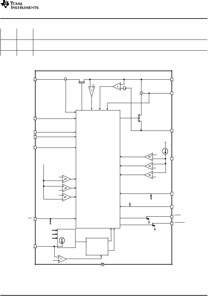
SIMPLIFIED BLOCK DIAGRAM |
|
|
|
IN |
|
Q1 |
OUT |
|
VO(SCI) |
||
|
|
|
|
|
|
OUTSC2 |
|
|
|
250 mV |
ISET |
|
|
OUT-SC1 |
|
ILIM |
|
|
Q2 |
|
|
|
|
EN2 |
|
|
BAT |
|
|
|
|
EN1 |
|
|
INTC |
|
|
|
|
ITERM |
|
|
|
('74) |
|
|
|
|
|
|
VHOT |
VIN |
|
|
TS |
|
|
|
|
|
|
CHARGE AND DYNAMIC |
VCOLD |
|
|
POWER PATH |
|
VBAT + VIN-DT |
MANAGEMENT CONTROL |
VDIS(TS) |
|
|
|
|
|
VUVLO |
|
|
TD |
VOVP |
|
|
('72, '73) |
|
|
|
VBAT |
|
|
|
SYSOFF |
|
|
|
('75) |
|
|
|
CHG |
CE |
|
|
|
|
|
|
PGOOD |
V IPRECHG |
Dynamically |
|
|
VICHG |
Controlled |
|
|
Oscillator |
|
|
|
VISET |
|
|
|
|
|
|
|
|
|
FAST-CHARGE |
|
TMR |
|
and |
|
|
PRE-CHARGE |
|
|
|
|
|
|
|
|
TIMERS |
|
-100 mV |
Timers disabled |
|
|
|
|
||
|
|
VSS |
|
Copyright © 2008, Texas Instruments Incorporated |
Submit Documentation Feedback |
7 |
Product Folder Link(s): bq24072 bq24073 bq24074 bq24075

bq24072, bq24073 bq24074, bq24075
SLUS810–SEPTEMBER 2008
ADAPTER REMOVAL
BATTERY CONNECTED
ROUT = 6.6Ω
|
|
|
|
|
|
|
ROUT = 6.6 Ω |
|
200 mA |
|
|
|
|
Battery Supplying |
IBAT |
|
|
|
Load |
|
|
|
|
-200 mA |
|
|
|
|
Charging Battery |
VOUT |
|
|
|
|
4.4 V |
|
|
|
|
|
|
|
|
500 mV/div |
VBAT |
|
|
|
2 V/div |
|
|
|
|
|
4 V |
|
|
|
|
VIN |
|
|
|
5 V |
|
|
|
|
|
|
|
|
|
0 V |
|
|
|
|
|
|
|
|
40 ms/div |
|
Figure 1.
DROPOUT VOLTAGE vs
TEMPERATURE
|
0.7 |
|
|
|
|
|
|
|
|
|
|
|
|
|
|
IL = 1 A |
|
|
|
|
|
|
|
|
|
OUT |
0.6 |
|
|
|
|
|
|
|
|
|
|
|
|
|
|
|
|
|
|
|
|
|
|
||
|
|
|
|
|
|
|
|
|
|
|
|
|
V |
0.5 |
|
|
|
|
|
|
|
|
|
|
|
- |
|
|
|
|
|
|
|
|
|
|
|
|
IN |
|
|
|
|
|
|
|
|
|
|
|
|
-V |
0.4 |
|
|
|
|
|
|
|
|
|
|
|
DropoutVoltage |
|
|
|
|
|
|
|
|
|
|
|
|
0.3 |
|
|
|
|
|
|
|
|
|
|
|
|
|
0.2 |
|
|
|
|
|
|
|
|
|
|
|
|
0.1 |
|
|
|
|
|
|
|
|
|
|
|
|
0 |
|
|
|
|
|
|
|
|
|
|
|
|
0 |
25 |
50 |
75 |
100 |
125 |
||||||
TJ - Junction Temperature - °C
Figure 4.
www.ti.com
TYPICAL CHARACTERISTICS
ADAPTER HOT-PLUG
NO BATTERY CONNECTED
VOUT
2 V/div
2 V/div
VBAT
VIN |
5 V/div |
|
|
200 ms/div |
|
|
Figure 2. |
|
|
DROPOUT VOLTAGE |
|
|
vs |
|
|
TEMPERATURE |
|
|
NO INPUT SUPPLY |
|
120 |
|
|
|
IL = 1 A |
|
100 |
|
OUT |
|
|
-V |
|
|
BAT |
80 |
VBAT = 3 V |
|
|
|
-V |
|
|
DropoutVoltage |
60 |
VBAT = 3.9 V |
|
|
|
|
40 |
|
|
20 |
|
0
0 |
25 |
50 |
75 |
100 |
125 |
TJ - Junction Temperature - °C
|
ADAPTER HOT-PLUG |
|
BATTERY CONNECTED |
IBAT |
100 mA/div |
|
|
|
-200 mA |
|
Charging Battery |
VOUT |
500 mV/div |
VBAT |
|
4 V |
2 V/div |
VIN |
5 V/div |
|
40 ms/div |
Figure 3.
bq24072
OUTPUT REGULATION VOLTAGE vs
BATTERY VOLTAGE
|
4.6 |
|
|
|
|
|
|
|
VIN = 5 V |
|
|
|
|
|
4.4 |
|
|
|
|
|
-V |
4.2 |
|
|
|
|
|
|
|
|
|
|
|
|
Voltage |
4 |
|
|
|
|
|
3.8 |
|
|
|
|
|
|
-Output |
|
|
|
|
|
|
3.6 |
|
|
|
|
|
|
|
|
|
|
|
|
|
O |
|
|
|
|
|
|
V |
3.4 |
|
|
|
|
|
|
3.2 |
|
|
|
|
|
|
3 |
|
|
|
|
|
|
2 |
2.5 |
3 |
3.5 |
4 |
4.5 |
|
|
|
VBAT - Battery Voltage - V |
|
||
Figure 5. |
Figure 6. |
O
V -OutputVoltage -V
|
|
|
|
bq24072 |
|
|
|
|
|||
OUTPUT REGULATION VOLTAGE |
|||||||||||
|
|
|
|
|
|
vs |
|
|
|
|
|
|
|
|
TEMPERATURE |
|
|
|
|
||||
3.80 |
|
|
|
|
|
|
|
|
|
|
|
3.78 |
|
VIN = 5 V, |
|
|
|
|
|
|
|
|
|
|
VBAT = 3.5 V, |
|
|
|
|
|
|
|
|
||
|
|
|
|
|
|
|
|
|
|
||
3.76 |
|
IL = 1 A |
|
|
|
|
|
|
|
|
|
|
|
|
|
|
|
|
|
|
|||
3.74 |
|
|
|
|
|
|
|
|
|
|
|
|
|
|
|
|
|
|
|
|
|
|
|
3.72 |
|
|
|
|
|
|
|
|
|
|
|
|
|
|
|
|
|
|
|
|
|
|
|
3.70 |
|
|
|
|
|
|
|
|
|
|
|
|
|
|
|
|
|
|
|
|
|
|
|
|
|
|
|
|
|
|
|
|
|
|
|
3.68 |
|
|
|
|
|
|
|
|
|
|
|
|
|
|
|
|
|
|
|
|
|
|
|
3.66 |
|
|
|
|
|
|
|
|
|
|
|
|
|
|
|
|
|
|
|
|
|
|
|
3.64 |
|
|
|
|
|
|
|
|
|
|
|
|
|
|
|
|
|
|
|
|
|
|
|
3.62 |
|
|
|
|
|
|
|
|
|
|
|
|
|
|
|
|
|
|
|
|
|
|
|
3.60 |
|
|
|
|
|
|
|
|
|
|
|
|
|
|
|
|
|
|
|
|
|
|
|
0 |
25 |
50 |
75 |
100 |
125 |
||||||
TJ - Junction Temperature - °C
Figure 7.
O
V -OutputVoltage -V
bq24073/ 74
OUTPUT REGULATION VOLTAGE vs
TEMPERATURE
4.45
VIN = 5 V,
4.43IL = 1 A
4.40
4.38
4.35
4.33
4.30
0 |
25 |
50 |
75 |
100 |
125 |
TJ - Junction Temperature - °C
Figure 8.
bq24075
OUTPUT REGULATION VOLTAGE vs
TEMPERATURE
|
5.75 |
|
|
|
|
|
|
|
|
|
|
|
|
|
5.70 |
|
VIN = 6 V, |
|
|
|
|
|
|
|
|
||
|
|
IL |
= 1 A |
|
|
|
|
|
|
|
|
||
|
|
|
|
|
|
|
|
|
|
|
|||
-V |
5.65 |
|
|
|
|
|
|
|
|
|
|
|
|
|
|
|
|
|
|
|
|
|
|
|
|
||
5.60 |
|
|
|
|
|
|
|
|
|
|
|
|
|
Voltage |
5.55 |
|
|
|
|
|
|
|
|
|
|
|
|
|
|
|
|
|
|
|
|
|
|
|
|
|
|
Output- |
5.50 |
|
|
|
|
|
|
|
|
|
|
|
|
|
|
|
|
|
|
|
|
|
|
|
|
||
5.45 |
|
|
|
|
|
|
|
|
|
|
|
|
|
|
|
|
|
|
|
|
|
|
|
|
|
|
|
O |
5.40 |
|
|
|
|
|
|
|
|
|
|
|
|
|
|
|
|
|
|
|
|
|
|
|
|
||
V |
|
|
|
|
|
|
|
|
|
|
|
|
|
|
5.35 |
|
|
|
|
|
|
|
|
|
|
|
|
|
|
|
|
|
|
|
|
|
|
|
|
|
|
|
5.30 |
|
|
|
|
|
|
|
|
|
|
|
|
|
|
|
|
|
|
|
|
|
|
|
|
|
|
|
5.25 |
|
|
|
|
|
|
|
|
|
|
|
|
|
0 |
|
25 |
50 |
75 |
100 |
125 |
||||||
|
|
|
|
TJ - Junction Temperature - °C |
|
|
|||||||
Figure 9.
8 |
Submit Documentation Feedback |
Copyright © 2008, Texas Instruments Incorporated |
Product Folder Link(s): bq24072 bq24073 bq24074 bq24075

|
bq24072, bq24073 |
|
bq24074, bq24075 |
www.ti.com |
SLUS810–SEPTEMBER 2008 |
TYPICAL CHARACTERISTICS (continued)
BAT
V -RegulationVoltage -V
|
bq24072/ 73/ 75 |
bq24074 |
BAT REGULATION VOLTAGE |
OVERVOLTAGE PROTECTION |
OVERVOLTAGE PROTECTION |
THRESHOLD |
THRESHOLD |
|
vs |
vs |
vs |
TEMPERATURE |
TEMPERATURE |
TEMPERATURE |
4.210
4.205
4.200
4.195
4.190
4.185
4.180 |
|
|
|
|
|
|
0 |
5 |
10 |
15 |
20 |
25 |
30 |
TJ - Junction Temperature - °C
Figure 10.
|
10.70 |
|
|
|
|
|
|
|
6.70 |
|
|
|
|
|
|
|
|
10.5 V |
|
|
|
|
|
-OutputVoltageThreshold -V |
|
6.6 V |
|
|
|
|
|
-OutputVoltageThreshold -V |
10.65 |
|
|
|
|
|
|
|
|
|
|
|
|
||
|
|
|
|
|
|
|
|
|
|
|
|
|
|||
10.60 |
|
|
VI |
Rising |
|
|
6.65 |
|
|
|
|
|
|
||
|
|
|
|
|
|
|
|
VI |
Rising |
|
|
||||
10.55 |
|
|
|
|
|
|
|
|
|
|
|
||||
10.50 |
|
|
|
|
|
|
6.60 |
|
|
|
|
|
|
||
10.45 |
|
|
|
|
|
|
|
|
|
|
|
|
|
||
10.40 |
|
|
VI |
Falling |
|
|
6.55 |
|
|
|
|
|
|
||
10.35 |
|
|
|
|
|
|
|
|
|
VI |
Falling |
|
|
||
|
|
|
|
|
|
|
|
|
|
|
|
||||
10.30 |
|
|
|
|
|
|
|
|
|
|
|
|
|
||
OVP |
|
|
|
|
|
|
OVP |
6.50 |
|
|
|
|
|
|
|
|
|
|
|
|
|
|
|
|
|
|
|
|
|
||
V |
10.25 |
|
|
|
|
|
|
V |
|
|
|
|
|
|
|
|
|
|
|
|
|
|
|
|
|
|
|
|
|
|
|
|
10.20 |
|
|
|
|
|
|
|
6.45 |
|
|
|
|
|
|
|
0 |
25 |
50 |
75 |
100 |
125 |
|
0 |
25 |
50 |
75 |
100 |
125 |
||
|
|
TJ - Junction Temperature - °C |
|
|
|
TJ - Junction Temperature - °C |
|
||||||||
|
|
|
Figure 11. |
|
|
|
|
|
Figure 12. |
|
|
||||
bq24072/ 73/ 75 |
bq24074 |
FASTCHARGE CURRENT |
INPUT CURRENT LIMIT |
INPUT CURRENT LIMIT |
|
vs |
vs |
vs |
INPUT VOLTAGE |
INPUT VOLTAGE |
BATTERY VOLTAGE |
|
800 |
|
|
|
|
|
|
|
|
|
|
RILIM |
|
|
700 |
|
|
|
|
|
|
|
|
|
|
|
-A |
CurrentInput-mA |
600 |
|
|
|
|
CurrentCharge |
500 |
|
|
|
USB500 |
||
|
|
|
|
|
|
|
|
400 |
|
|
|
|
|
|
300 |
|
|
|
|
-Fast |
LIM 200 |
|
|
|
|
||
- |
|
|
|
|
|
|
I |
|
|
|
|
USB100 |
BAT |
|
|
|
|
|
I |
|
|
100 |
|
|
|
|
|
|
0 |
|
|
|
|
|
|
5 |
6 |
7 |
8 |
9 |
10 |
|
|
|
VI - Input Voltage - V |
|
||
1.05
R = 900 Ω ISET
1.03
1.01
0.99
0.97
0.95
3 |
3.2 |
3.4 |
3.6 |
3.8 |
4 |
4.2 |
VBAT - Battery Voltage - V
BAT
I -FastChargeCurrent - A
310
R = 3 kΩ
ISET
305
300

295
290
285
280
3 |
3.2 |
3.4 |
3.6 |
3.8 |
4 |
4.2 |
|
|
VBAT - Battery Voltage - V |
|
|
||
Figure 13. |
Figure 14. |
Figure 15. |
FASTCHARGE CURRENT |
|
PRECHARGE CURRENT |
vs |
|
vs |
BATTERY VOLTAGE |
|
BATTERY VOLTAGE |
BAT
I -PrechargeCurrent - A
105 |
|
|
|
|
|
|
|
|
|
R = 900 Ω |
|
|
|
||
104 |
|
ISET |
|
|
|
||
|
|
|
|
|
|
|
|
103 |
|
|
|
|
|
|
|
|
|
|
|
|
|
|
|
102 |
|
|
|
|
|
|
|
|
|
|
|
|
|
|
|
101 |
|
|
|
|
|
|
|
|
|
|
|
|
|
|
|
100 |
|
|
|
|
|
|
|
|
|
|
|
|
|
|
|
99 |
|
|
|
|
|
|
|
|
|
|
|
|
|
|
|
98 |
|
|
|
|
|
|
|
|
|
|
|
|
|
|
|
97 |
|
|
|
|
|
|
|
96 |
|
|
|
|
|
|
|
95 |
|
|
|
|
|
|
|
|
|
|
|
|
|
|
|
2 2.2 2.4 2.6 2.8 3
VBAT - Battery Voltage - V
BAT
I -PrechargeCurrent - A
31.5
R = 3 kΩ
ISET
31
30.5
30
29.5
29
28.5
2 |
2.2 |
2.4 |
2.6 |
2.8 |
3 |
VBAT - Battery Voltage - V
Figure 16. |
Figure 17. |
Copyright © 2008, Texas Instruments Incorporated |
Submit Documentation Feedback |
9 |
Product Folder Link(s): bq24072 bq24073 bq24074 bq24075

bq24072, bq24073 bq24074, bq24075
SLUS810–SEPTEMBER 2008 |
www.ti.com |
EXPLANATION OF DEGLITCH TIMES AND COMPARATOR HYSTERESIS
Figures not to scale
VOVP
VOVP - Vhys(OVP)
VBAT + VIN(DT)
VBAT + VIN(DT) - Vhys(INDT)
UVLO
UVLO - Vhys(UVLO)
PGOOD
VIN |
Typical Input Voltage |
t < tDGL(OVP) |
Operating Range |
tDGL(PGOOD) |
|
tDGL(OVP) |
tDGL(NO-IN) |
tDGL(PGOOD) |
|
Figure 18. Power-Up, Power-Down
V |
BAT |
|
tDGL1(LOWV) |
|
VLOWV |
|
|
|
|
|
t < tDGL1(LOWV) |
tDGL1(LOWV) |
tDGL2(LOWV) |
t < tDGL2(LOWV) |
ICHG |
|
|
|
Fast-Charge |
|
|
Fast-Charge |
|
|
|
|
|
|
|
IPRE-CHG |
Pre-Charge |
|
|
|
|
|
Pre-Charge |
|
|
|
|
|
|
|
Figure 19. Preto Fast-Charge, Fastto Pre-Charge Transition – tDGL1(LOWV), tDGL2(LOWV) |
||||
VBAT |
|
|
VRCH |
|
|
|
|
Re-Charge |
t < tDGL(RCH) |
t |
DGL(RCH) |
|
|
Figure 20. Recharge – tDGL(RCH)
10 |
Submit Documentation Feedback |
Copyright © 2008, Texas Instruments Incorporated |
Product Folder Link(s): bq24072 bq24073 bq24074 bq24075
www.ti.com
Turn |
Force |
Turn |
Q2 OFF |
Q2 ON |
Q2 OFF |
|
tREC(SC2) |
|
|
VBAT - VOUT |
|
VO(SC2)
t < tDGL(SC2) tDGL(SC2) |
tDGL(SC2) |
bq24072, bq24073 bq24074, bq24075
SLUS810–SEPTEMBER 2008
Force
Q2 ON
tREC(SC2)
Recover
t < tDGL(SC2)
Figure 21. OUT Short-Circuit – Supplement Mode
VCOLD |
|
|
|
VCOLD - Vhys(COLD) |
|
|
|
|
|
Suspend |
|
|
|
Charging |
|
t < tDGL(TS) |
tDGL(TS) |
Resume |
|
Charging |
|||
VTS |
|
||
|
|
||
VHOT - Vhys(HOT) |
|
|
|
VHOT |
|
|
Figure 22. Battery Pack Temperature Sensing – TS Pin. Battery Temperature Increasing
DETAILED FUNCTIONAL DESCRIPTION
The bq2407x devices are integrated Li-Ion linear chargers and system power path management devices targeted at space-limited portable applications. The device powers the system while simultaneously and independently charging the battery. This feature reduces the number of charge and discharge cycles on the battery, allows for proper charge termination and enables the system to run with a defective or absent battery pack. It also allows instant system turn-on even with a totally discharged battery. The input power source for charging the battery and running the system can be an AC adapter or a USB port. The devices feature Dynamic Power Management, which shares the source current between the system and battery charging, and automatically reduces the charging current if the system load increases. Additionally, when charging from a USB port, the device reduces the input current if the input voltage falls below a threshold, preventing the USB port from crashing. The power-path architecture also permits the battery to supplement the system current requirements when the adapter cannot deliver the peak system currents. The startup state diagram is shown in Figure 23.
Copyright © 2008, Texas Instruments Incorporated |
Submit Documentation Feedback |
11 |
Product Folder Link(s): bq24072 bq24073 bq24074 bq24075
Loading...