


Texas Instruments AM26LS31MJ, AM26LS31MFK, AM26LS31CNSR, AM26LS31CN, AM26LS31CDR Datasheet
...AM26LS31C, AM26LS31M
QUADRUPLE DIFFERENTIAL LINE DRIVER
SLLS114H – JANUARY 1979 – REVISED JULY 2002
D Meets or Exceeds the Requirements of |
D, DB, N, NS, OR J PACKAGE |
||||||||
|
ANSI TIA/EIA-422-B and ITU |
|
|
(TOP VIEW) |
|
|
|||
|
Recommendation V.11 |
1A |
|
|
|
|
|
VCC |
|
|
|
1 |
16 |
|
|
||||
D Operates From a Single 5-V Supply |
|
|
|
||||||
1Y |
|
2 |
15 |
|
|
4A |
|||
D |
TTL Compatible |
|
|
|
|||||
1Z |
|
|
|
|
|
4Y |
|||
|
3 |
14 |
|
|
|||||
|
|
|
|
|
|||||
D |
Complementary Outputs |
G |
|
4 |
13 |
|
|
4Z |
|
|
|
|
|||||||
|
|
2Z |
|
|
|
|
|
|
|
D High Output Impedance in Power-Off |
|
5 |
12 |
|
|
G |
|
||
|
Conditions |
2Y |
|
6 |
11 |
|
|
3Z |
|
D Complementary Output-Enable Inputs |
2A |
|
7 |
10 |
|
|
3Y |
||
|
|
GND |
|
8 |
9 |
|
|
3A |
|
description/ordering information
The AM26LS31 is a quadruple complementary-output line driver designed to meet the requirements of ANSI TIA/EIA-422-B and ITU (formerly CCITT) Recommendation V.11. The 3-state outputs have high-current capability for driving balanced lines such as twisted-pair or parallel-wire transmission lines, and they are in the high-impedance state in the power-off condition. The enable function is common to all four drivers and offers the choice of an active-high
or active-low enable (G, G) input. Low-power Schottky circuitry reduces power consumption without sacrificing speed.
FK PACKAGE (TOP VIEW)
|
1Y |
1A |
NC |
CC |
4A |
|
|
V |
|
||||
|
3 |
2 |
1 |
20 |
19 |
|
1Z |
4 |
|
|
|
18 |
4Y |
G |
5 |
|
|
|
17 |
4Z |
NC |
6 |
|
|
|
16 |
NC |
2Z |
7 |
|
|
|
15 |
G |
2Y |
8 |
|
|
|
14 |
3Z |
|
9 |
10 |
11 |
12 |
13 |
|
|
2A |
GND |
NC |
3A |
3Y |
|
ORDERING INFORMATION
T |
|
PACKAGE† |
ORDERABLE |
TOP-SIDE |
|
|
|
|
|||
A |
|
|
|
PART NUMBER |
MARKING |
|
|
|
|
||
|
PDIP – N |
|
Tube |
AM26LS31CN |
AM26LS31CN |
|
|
|
|
|
|
|
SOIC – D |
|
Tube |
AM26LS31CD |
AM26LS31C |
0° C to 70° C |
|
|
|
||
|
Tape and reel |
AM26LS31CDR |
|||
|
|
|
|||
|
|
|
|
|
|
|
SOP – NS |
|
Tape and reel |
AM26LS31CNSR |
26LS31 |
|
|
|
|
|
|
|
SSOP – DB |
|
Tape and reel |
AM26LS31CDBR |
SA31C |
|
|
|
|
|
|
–55° C to 125° C |
CDIP – J |
|
Tube |
AM26LS31MJ |
AM26LS31MJB |
|
|
|
|
|
|
LCCC – FK |
|
Tube |
AM26LS31MFK |
AM26LS31MFKB |
|
|
|
||||
†Package drawings, standard packing quantities, thermal data, symbolization, and PCB design guidelines are available at www.ti.com/sc/package.
Please be aware that an important notice concerning availability, standard warranty, and use in critical applications of Texas Instruments semiconductor products and disclaimers thereto appears at the end of this data sheet.
PRODUCTION DATA information is current as of publication date. Products conform to specifications per the terms of Texas Instruments standard warranty. Production processing does not necessarily include testing of all parameters.
Copyright 2002, Texas Instruments Incorporated
On products compliant to MIL-PRF-38535, all parameters are tested unless otherwise noted. On all other products, production processing does not necessarily include testing of all parameters.
POST OFFICE BOX 655303 • DALLAS, TEXAS 75265 |
1 |
AM26LS31C, AM26LS31M
QUADRUPLE DIFFERENTIAL LINE DRIVER
SLLS114H – JANUARY 1979 – REVISED JULY 2002
FUNCTION TABLE (each driver)
INPUT |
ENABLES |
OUTPUTS |
||||
A |
|
|
|
|
|
|
G |
G |
Y |
Z |
|||
|
||||||
|
|
|
|
|
||
H |
H |
X |
H |
L |
||
L |
H |
X |
L |
H |
||
H |
X |
L |
H |
L |
||
L |
X |
L |
L |
H |
||
X |
L |
H |
Z |
Z |
||
|
|
|
|
|
|
|
H = high level, L = low level, X = irrelevant,
Z = high impedance (off)
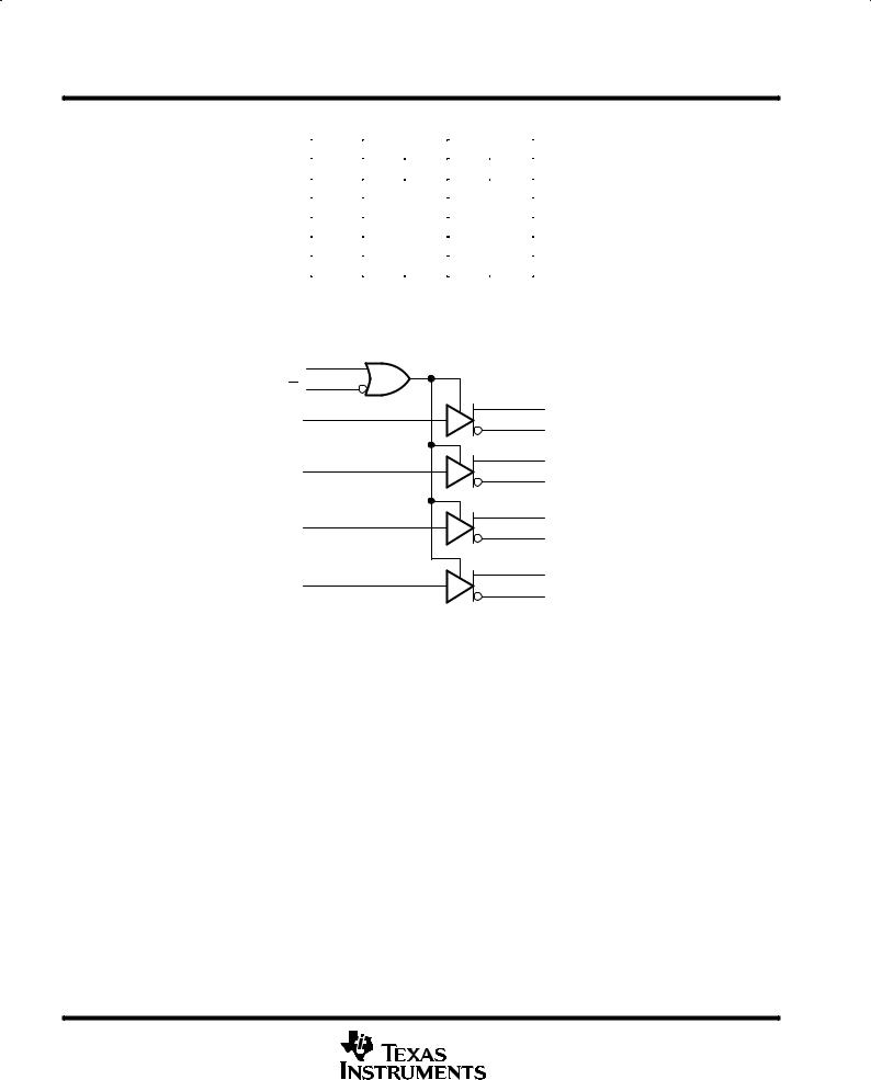
logic diagram (positive logic)
4
G |
|
|
|
12 |
|
|
|
G |
2 |
|
|
1 |
1Y |
||
|
|||
1A |
3 |
1Z |
|
|
|
||
7 |
6 |
2Y |
|
5 |
|||
2A |
2Z |
||
|
|
||
9 |
10 |
3Y |
|
11 |
|||
3A |
3Z |
||
|
|
||
15 |
14 |
4Y |
|
13 |
|||
4A |
4Z |
||
|
|
2 |
POST OFFICE BOX 655303 • DALLAS, TEXAS 75265 |

AM26LS31C, AM26LS31M
QUADRUPLE DIFFERENTIAL LINE DRIVER
SLLS114H – JANUARY 1979 – REVISED JULY 2002
schematic (each driver)
Input A
V |
|
22 kΩ |
|
|
|
9 Ω |
|
9 Ω |
|
|
|
Output Y |
|
Output Z |
|
|
|
Common to All Four Drivers |
|
|
VCC |
|
|
V |
22 kΩ |
|
|
|
|
|
22 kΩ |
To Three Other Drivers |
Enable G |
|
|
Enable G |
|
|
GND |
|
|
All resistor values are nominal.
POST OFFICE BOX 655303 • DALLAS, TEXAS 75265 |
3 |
 Loading...