


Texas Instruments BQ2150MODULE, BQ2150LMODULE, BQ2150LB-KT, BQ2150LB-012, BQ2150LB-011 Datasheet
...bq2150
Li-Ion Power Gauge™ Module
Features
Complete bq2050 Power Gauge solution for Li-Ion battery packs
Battery information available over a single-wire bidirectional serial port
Battery state-of-charge monitoring for 2- to 4-cell series applications
On-board regulator allows direct connection to the battery
“L” version includes push-button activated LEDs to display state-of-charge information
Nominal capacity pre-configured
Compact size for battery pack integration
General Description
The bq2150 Power Gauge Module provides a complete and compact solution for capacity monitoring of Li-Ion battery packs. Designed for battery pack integration, the bq2150 incorporates a bq2050 Gas Gauge IC, a current sense resistor, and all other components necessary to accurately monitor and display the capacity of 2 to 4 series cells.
The bq2150L includes five LEDs to display remaining capacity in 20% increments of the learned capacity. The LEDs are activated with the onboard push-button switch.
A module development kit is also available for the bq2150. The bq2150B-KT or the bq2150LB-KT includes one configured module and the following:
1)An interface board that allows connection to the serial port of an AT-compatible computer.
2)Menu-driven software to display charge/discharge activity and to allow user interface to the bq2050 from any standard DOS PC.
3)Source code for the TSR.
Pin Descriptions
Contacts are provided on the bq2150 for direct connection to the battery stack (BAT+, BAT-) and the serial communications port (DQ). The RBI input provides backup power to the bq2050 in the event that the cells are removed or the battery is turned off. The bq2150 has a 1 F capacitor onboard connected to RBI to supply backup power for about an hour. In battery packs that use high-side FETs to control the charge/discharge of the Li-Ion cells, the RBI input can be wired to a single cell to provide prolonged data retention times. The SD input allows an external signal (active low) to turn the bq2050 IC off to minimize internal current consumption of the battery pack and maximize storage life of the pack in the system. When turned off, the bq2050 is nonfunctional, and the RBI power source maintains register information. Please refer to the bq2050 data sheet for the specifics on the operation of the gas gauge.
Unitrode configures the bq2150 based on the information requested in Table 1. The configuration defines the number of series cells, the nominal battery pack capacity, and the Li-Ion battery type (coke or graphite anode). Figure 1 shows how the module connects to the cells.
5/99 B
P1 |
DQ/Serial Communications port |
P2 |
No connect |
P3 |
BAT+/Battery positive/pack positive |
P4 |
SD/Shutdown |
P5 |
RBI/Register backup input |
P6 |
GND/Ground |
P7 |
PACK-/Pack negative |
P8 |
BAT-/Battery negative |
1
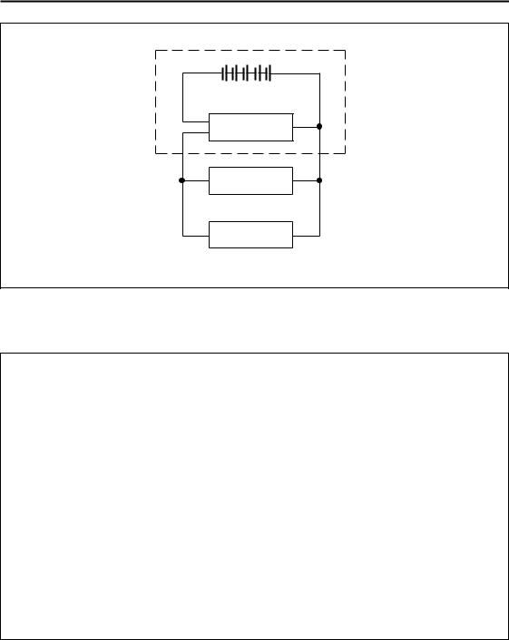
bq2150
Battery Pack
Cells
P8
bq2150 P3
P7
PACK- |
PACK+ |
Load
Charger
FG-9611
Figure 1. Module Connection Diagram
Table 1. bq2150 Module Configuration
Customer Name: ___________________________________________________________________________
Contact: _________________________________________ Phone: ______________________________
Address: _________________________________________________________________________________
_________________________________________________________________________________
Sales Contact: ____________________________________ |
Phone: ______________________________ |
|
Number of series battery cells (2-4) |
____________________ |
|
Coke or graphite cell anode |
____________________ |
|
Battery pack capacity (mAh) |
____________________ |
|
Discharge rate into load (3.0A max) |
Min. ________ Avg. _________ Max. _________ |
|
Charge rate (3.0A max) |
____________________ |
|
Nominal Available Capacity after reset |
|
|
(Programmed Capacity or Zero) |
____________________ |
|
Self-discharge compensation (Y/N) |
____________________ |
|
LEDs and switch (Y/N) |
____________________ |
|
FAE Approval: _____________________________________ |
Date:________________________________ |
|
2

bq2150
bq2150 Schematic
Note: Schematic shows components that may not be placed on the board, depending on the configuration.
3
 Loading...