


Texas Instruments BQ2114MODULE, BQ2114LMODULE, BQ2114LB-KT, BQ2114LB-018, BQ2114LB-016 Datasheet
...bq2114
NiCd or NiMH Gas Gauge Module
with Charge-Control Output
Features
Complete bq2014 Gas Gauge solution for NiCd or NiMH battery packs
Charge-control output allows communication to external charge controller (bq2004)
Battery information available over a single-wire bidirectional serial port
Battery state-of-charge monitoring for 4- to 12-cell series applications
On-board regulator allows direct connection to the battery
“L” version includes push-button activated LEDs to display state-of-charge information
Nominal capacity and cell chemistry pre-configured
Compact size for battery pack integration
General Description
The bq2114 Gas Gauge Module provides a complete and compact solution for capacity monitoring of NiCd and NiMH battery packs. Designed for battery pack integration, the bq2114 incorporates a bq2014 Gas Gauge IC, a current sense resistor, and all other components necessary to accurately monitor and display the capacity of 4 to 12 series cells. The bq2114L includes five surfacemounted LEDs to display remaining capacity in 20% increments of the learned capacity (relative mode). The LEDs are activated with the onboard push-button switch.
Contacts are provided on the bq2114 for direct connection to the battery stack (BAT+, BAT-), the serial communications port (DQ), the empty indicator (EMPTY), and the charge control output (CHG). Please refer to the bq2014 data sheet for the specifics on the operation of the Gas Gauge.
Unitrode configures the bq2114 based on the information requested in Table 1. The configuration defines the number of series cells, the nominal battery pack capacity, and the self-discharge rate.
A module development kit is also available for the bq2114. The bq2114B-KT or bq2114LB-KT includes one configured module and the following:
1)An interface board that allows connection to the serial port of an AT-compatible computer.
2)Menu-driven software with the bq2114 to display charge/discharge activity and to allow user interface to the bq2014 from any standard DOS PC.
3)Source code for the TSR.
Pin Descriptions
P1 |
DQ/Serial communication port |
P2 |
BAT+/Battery positive/pack positive |
P3 |
CHG/Charge control output |
P4 |
EMPTY/Empty indicator output |
P5 |
GND/Ground |
P6 |
PACK-/Pack negative |
P7 |
BAT-/Battery negative |
5/99 B
1
bq2114
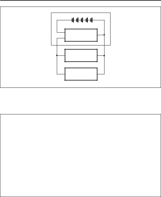
Battery Pack
Cells
P7
bq2114 P2
P6
PACK- |
PACK+ |
Load
Charger
FG211401.eps
Figure 1. Module Connection Diagram
Table 1. bq2114 Module Configuration
Customer Name: ___________________________________________________________________________
Contact: _________________________________________ Phone: ______________________________
Address: _________________________________________________________________________________
_________________________________________________________________________________
Sales Contact: ____________________________________ |
Phone: ______________________________ |
||||||
Number of series battery cells (4–12) |
________________________________________ |
||||||
Battery type (NiCd or NiMH) |
________________________________________ |
||||||
Battery pack capacity (mAh) |
________________________________________ |
||||||
Discharge rate into load (3.0A max.) |
Min. |
|
Avg. |
|
Max. |
|
|
Charge rate (3.0A max.) |
________________________________________ |
||||||
LEDs and switch (Y/N) |
________________________________________ |
||||||
FAE approval: _____________________________________ |
Date:________________________________ |
||||||
2

bq2114
bq2114 Schematic
Note: Schematic shows components which may not be placed on the board, depending upon the configuration.
3
 Loading...