


 Loading...
REVISION HISTORY TG1 (GA) CHASSIS
MODEL |
PART NO.: 9-888-100-01 |
KLV-26T400A
KLV-26T400G
KLV-32T400A
NO. |
SUFFIX |
DATE |
SUPP / CORR |
DESCRIPTION |
|
|
|
|
|
1 |
-01 |
2008/08 |
_ _ |
1st Issue |
|
|
|
|
|
|
|
|
|
|
|
|
|
|
|
|
|
|
|
|
|
|
|
|
|
|
|
|
|
|
|
|
|
|
|
|
|
|
|
|
|
|
|
|
|
|
|
|
|
|
|
|
|
|
|
|
|
|
|
|
|
|
|
|
|
|
|
|
|
|
|
|
|
|
|
|
|
|
|
|

|
SERVICE MANUAL |
|
|
|
|
TG1 (GA) CHASSIS |
||||||||||||||||||||||||||||||||||||
|
MODEL |
COMMANDER DEST. |
|
|
MODEL |
|
COMMANDER DEST. |
|||||||||||||||||||||||||||||||||||
|
|
|||||||||||||||||||||||||||||||||||||||||
|
|
|
|
|
|
|
|
|
|
|
|
|
|
|
|
|
|
|
|
|
|
|
|
|
|
|
|
|
|
|
|
|
|
|
|
|
|
|
|
|
|
|
|
KLV-26T400A |
|
RM-GA013 E, GE, India, ME, |
|
|
|
|
|
|
|
|
|
|
|
|
|
|
|
|
|
|
|
|
|
|
|
||||||||||||||||
|
|
|
|
|
|
|
|
|
|
|
|
|
|
|
New Zealand, |
|
|
|
|
|
|
|
|
|
|
|
|
|
|
|
|
|
|
|
|
|
|
|
||||
|
KLV-26T400G |
|
|
|
|
|
|
|
|
|
|
South Africa |
|
|
|
|
|
|
|
|
|
|
|
|
|
|
|
|
|
|
|
|
|
|
|
|||||||
|
|
RM-GA013 E, GE, India, ME, |
|
|
|
|
|
|
|
|
|
|
|
|
|
|
|
|
|
|
|
|
|
|
|
|||||||||||||||||
|
KLV-32T400A |
|
RM-GA013 E, GE, India, ME, |
|
|
|
|
|
|
|
|
|
|
|
|
|
|
|
|
|
|
|
|
|
|
|
||||||||||||||||
|
|
|
|
|
|
|
|
|
|
|
|
|
|
|
Thailand, South Africa |
|
|
|
|
|
|
|
|
|
|
|
|
|
|
|
|
|
|
|
|
|
|
|
||||
|
|
|
|
|
|
|
|
|
|
|
|
|
|
|
|
|
|
|
|
|
|
|
|
|
|
|
|
|
|
|
|
|
|
|
|
|
|
|
|
|
|
|
|
|
|
|
|
|
|
|
|
|
|
|
|
|
|
|
|
|
|
|
|
|
|
|
|
|
|
|
|
|
|
|
|
|
|
|
|
|
|
|
|
|
|
KLV-26T400A |
KLV-26T400G |
|
RM-GA013
KLV-32T400A
LCD COLOR TV
KLV-26T400A,T400G, 32T400A
RM-GA013
TABLE OF CONTENTS
Section Title |
Page |
Section Title |
Page |
||||||
|
|
|
|
|
|
|
|
|
|
1. |
SAFETY NOTES |
|
|
6. |
DIAGRAMS |
|
|
||
|
1-1. Caution Handling of LCD Panel ..................................... |
3 |
|
6-1. Block Diagram ............................................................... |
23 |
||||
|
1-2. Safety Check Out ............................................................. |
3 |
|
6-2. Connector Diagram ....................................................... |
23 |
||||
|
1-3. Leakage Test .................................................................... |
3 |
|
6-3. Circuit Board Location .................................................. |
25 |
||||
|
1-4. WARNING ! .................................................................... |
3 |
|
6-4. Schematic Diagram ....................................................... |
25 |
||||
|
1-5. Lead Free Information ..................................................... |
4 |
|
6-5. Printed Wiring Boards ................................................... |
25 |
||||
|
|
|
|
|
|
6-6. Semiconductor ............................................................... |
25 |
||
2. |
SELF DIAGNOSTIC FUNCTION |
|
|
|
|
|
|
|
|
|
2-1. Overview of Control Buttons .......................................... |
5 |
7. |
EXPLODED VIEWS |
|
|
|||
|
2-2. LED Display Specification .............................................. |
5 |
|
7-1. (KLV-26T400) |
|
|
|||
|
2-3. LED Display Control ....................................................... |
5 |
|
7-1-1. Rear Cabinet ...................................................... |
26 |
||||
|
2-4. LED Pattern ..................................................................... |
5 |
|
7-1-2. Power Cord, AC Cord Holder ........................... |
27 |
||||
|
2-5. Viewing the Service Diagnosis Display .......................... |
5 |
|
7-1-3. BT, HT, GPT ...................................................... |
28 |
||||
|
2-6. Standby LED Error Display ............................................ |
6 |
|
7-1-4. Speaker, Bezel Assy and LCD Panel ................ |
29 |
||||
|
|
|
|
|
|
7-2. (KLV-32T400) |
|
|
|
|
|
|
|
|
|
7-2-1. Rear Cabinet ...................................................... |
30 |
||
3. |
DISASSEMBLY |
|
|
|
7-2-2. Power Cord, AC Cord Holder ........................... |
31 |
|||
|
3-1. Stand Assy Removal ........................................................ |
7 |
|
7-2-3. BT, HT, GPT ...................................................... |
32 |
||||
|
3-2. Rear Cover Removal ........................................................ |
7 |
|
7-2-4. Speaker, Bezel Assy and LCD Panel ................ |
33 |
||||
|
3-3. GPT Board and Bracket Removal ................................... |
7 |
|
|
|
|
|
||
|
3-4. BT Board and Bracket Removal ..................................... |
8 |
|
|
|
|
|
||
|
3-5. Vesa Frame Removal ....................................................... |
8 |
8. |
ELECTRICAL PARTS LIST .............................................. |
34 |
||||
|
3-6. HT Board and Speaker Removal ..................................... |
8 |
|
|
|
|
|
||
|
3-7. LCD Panel and Bezel Assy Removal .............................. |
9 |
|
|
|
|
|
||
|
|
|
|
|
|
OPERATING INSTRUCTIONS |
|
|
|
4. |
WIRE DRESSING |
|
|
|
|
|
|
|
|
|
4-1. (KLV-26T400) ........................................................... |
.... 10 |
|
|
|
|
|
||
|
4-2. (KLV-32T400) ............................................................ |
... 15 |
|
|
|
|
|
||
5. SERVICE ADJUSTMENTS |
|
|
5-1. Accessing Diagnostic Menu .......................................... |
20 |
|
5-2. Viewing the Service Mode Display .............................. |
20 |
|
5-3. |
Control Keys Via Remote Commander ......................... |
20 |
5-4. |
Adjustment Method ....................................................... |
20 |
5-5. |
Table 1 ............................................................................ |
22 |
5-6. |
Board & Panel Replacement ......................................... |
22 |
– 2 –

KLV-26T400A,T400G, 32T400A
RM-GA013
SECTION 1
SAFETY NOTES
1-1. Caution Handling of LCD Panel
When installing the LCD Panel, make sure you are grounded with a wrist band.
When installing the LCD Panel on the wall, the panel must be secured using the 4 mounting holes on the rear cover.
1)Do not press the panel or frame edge to avoid the risk of electric shock.
2)Do not scratch or press on the panel with any sharp objects.
3)Do not leave the module in high temperature or in areas of high humidity for an extended period of time.
4)Do not expose the LCD panel to direct sunlight.
5)Avoid contact with water. It may cause short circuit within the module.
6)Disconnect the AC adapter when replacing the backlight (CCFL) or inverter circuit. (High voltage occurs at the inverter circuit at 650Vrms)
7)Always clean the LCD panel with a soft cloth material.
8)Use care when handling the wires or connectors of the inverter circuit. Damaging the wires may cause a short circuit.
9)Protect the panel from ESD to avoid damaging the electronic circuit (C-MOS).
1-2. Safety Check-Out
After correcting the original service problem, perform the following safety checks before releasing the set to the customer:-
1)Check the area of your repair for unsoldered or poorly soldered connections. Check the entire board surface for solder splashes and bridges.
2)Check the interboard wiring to ensure that no wires are "pinched" or contact high-wattage resistors.
3)Check all control knobs, shields, covers, ground straps and mounting hardware have been replaced. Be absolutely certain you have replaced all the insulators.
4)Look for unauthorized replacement parts, particularly transistors that were installed during a previous repair. Point them out to the customer and recommend their replacement.
5)Look for parts which, though functioning show obvious signs of deterioration. Point them out to the customer and recommend their replacement.
6)Check the line cords for cracks and abrasion. Recommend the replacement of any such line cord to the customer.
7)Check the antenna terminals, metal trim, "metallized" knobs, screws and all other exposed metal parts for AC leakage. Check leakage test as described next.
1-3. Leakage Test
The AC leakage from any exposed metal part to earth ground and from all exposed metal parts to any exposed metal part having a return to chassis must not exceed 0.5mA (500 microamperes). Leakage current can be measured by any one of the three methods:-
1.A commercial leakage tester such as the SIMPSON 229 or RCA WT-540A. Follow the manufacturers instructions to use those instructions.
2.A battery-operated AC milliampmeter. The DATA PRECISION 245 digital multimeter is suitable for this job.
3.Measuring the voltage drop across a resistor by means of a VOM or battery operated AC voltmeter. The 'limit' indication is 0.75V so analog meters must have an accurate low voltage scale. The SIMPSON'S 250 and SANWA SH-63TRD are examples of passive VOMs that are suitable. Nearly all battery operated digital multimeters that have a 2 VAC range are suitable. (see Figure 1.)
To Exposed Metal
Parts on Set
AC
0.15 F 1.5 kΩ Voltmeter
(0.75 V)
Earth Ground
Figure 1. AC voltmeter to check AC leakage
1-4. WARNING !
SAFETY-RELATED COMPONENT WARNING! COMPONENTS IDENTIFIED BY SHADING AND MARK ! ON THE EXPLODED VIEWS ARE CRITICAL FOR SAFE OPERATION. REPLACE THESE COMPONENTS WITH SONY PARTS WHOSE PART NUMBERS APPEAR AS SHOWN IN THIS MANUAL OR IN SUPPLEMENTS PUBLISHED BY SONY. CIRCUIT ADJUSTMENTS THAT ARE CRITICAL FOR SAFE OPERATION ARE IDENTIFIED IN THIS MANUAL. FOLLOW THESE PROCEDURES WHENEVER CRITICAL COMPONENTS ARE REPLACED OR IMPROPER OPERATION IS SUSPECTED.
– 3 –
KLV-26T400A,T400G, 32T400A
RM-GA013
1-5. Lead Free Information
The circuit boards used in these models have been processed using Lead Free Solder. The boards are identified by the LF logo located close to the board designation.
Figure 2: LF logo
Figure 3: LF logo on circuit board
The servicing of these boards requires special precautions. It is strongly recommended to use Lead Free Solder material in order to guarantee optimal quality of new solder joints. Lead Free Solder is available under the following part numbers:-
Part number |
Diameter |
Remarks |
7-640-005-19 |
0.3mm |
0.25Kg |
|
|
|
7-640-005-20 |
0.4mm |
0.50Kg |
7-640-005-21 |
0.5mm |
0.50Kg |
|
|
|
7-640-005-22 |
0.6mm |
0.25Kg |
|
|
|
7-640-005-23 |
0.8mm |
1.00Kg |
|
|
|
7-640-005-24 |
1.0mm |
1.00Kg |
7-640-005-25 |
1.2mm |
1.00Kg |
|
|
|
7-640-005-26 |
1.6mm |
1.00Kg |
|
|
|
Due to high melting point of Lead Free Solder, the soldering iron tip temperature needs to be set to 370 degrees centigrade. This requires soldering equipment capable of accurate temperature control coupled with a good heat recovery characteristics.
For more information on the use of Lead Free Solder, please refer to http://www.sony-training.com
– 4 –
KLV-26T400A,T400G, 32T400A
RM-GA013
SECTION 2
SELF DIAGNOSTIC FUNCTION
2-1. Overview of Control Buttons
|
|
|
|
|
|
|
|
|
|
|
|
|
|
|
|
|
|
|
|
|
|
|
|
|
|
|
|
|
|
|
|
|
|
|
|
|
|
|
|
|
|
|
|
|
|
|
|
|
|
|
|
|
|
|
|
|
|
|
|
|
|
|
|
|
|
|
|
|
|
|
|
|
|
|
|
|
|
|
|
|
|
|
|
|
|
|
|
|
|
|
|
|
|
|
|
|
|
|
|
|
|
|
|
|
|
|
|
|
|
|
|
|
|
|
|
|
|
|
|
|
|
|
|
|
|
|
|
|
|
|
|
|
|
|
|
|
|
|
|
|
|
|
|
|
|
|
|
|
|
|
|
|
|
|
|
|
|
|
|
|
|
|
|
|
|
|
|
|
|
|
|
|
|
|
|
|
|
|
|
Timer |
Power |
Remote Menu |
TV/ |
Volume |
|
Channel Power |
|||||||||||||
Indicator |
Standby |
Sensor |
Video |
|
|
|
|
|
|
|
|
|
|
|
|
|
|
||
|
Indicat |
|
|
|
|
|
|
|
|
|
|
|
|
|
|
|
|
|
|
|
|
|
|
|
|
|
|
|
|
|
|
|
|
|
|
|
|
|
|
2-2. LED Display Specification
LED Type |
Description |
|
Remark |
|
|
||
POWER |
Green: One LED |
Green lights at power ON. |
|
|
|||
|
|
|
|
|
|||
STANDBY |
Red: One LED |
Red lights during standby. |
|
|
|||
|
|
|
|
|
|||
|
Green/Amber |
Green lights during Picture |
|
|
|||
Timer |
: Two LEDs |
OFF and amber lights |
|
|
|||
|
|
during Timer activation. |
|
|
|||
|
|
|
|
|
|
||
2-3. LED Display Control |
|
|
|
|
|
||
|
|
|
|
|
|
||
Status |
Display |
|
Remark |
||||
Power LED Standby LED |
|||||||
|
|
|
|
||||
POWER ON |
Green lights |
OFF |
|
Microcomputer is |
|||
|
in a normal state. |
||||||
|
|
|
|
||||
|
|
|
|
||||
STANDBY |
OFF |
Red lights Microcomputer is |
|||||
|
|
|
|
in a sleep state. |
|||
Classify the Failure 


 trouble causes by
the no. of red blinking.
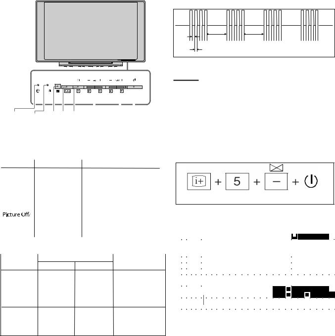
2-4. LED Pattern
When safety shutdown occurs, Standby LED display reports the cause by using the blinking patterns as indicated below.
2.0 sec |
2.0 sec |
0.3 sec |
|
0.3 sec |
|
Example:
The figure above shows LED display when SHUTDOWN is caused by audio failure. It repeats flashing for a specified number of times in 0.3sec/ cycle and has a 2 seconds interval of lighting off. Please note that a 2 seconds interval of lighting off is fixed regardless of abnormal state types.
2-5. Viewing the Service Diagnosis Display
1.While TV on standby mode, press the following sequence on the Remote commander.
On screen |
Channel 5 |
|
|
|
POWER |
Volume (-) |
|||||
display
(if wrong key is pressed or passed 3 seconds during each process, cancel entering the self-diagnosis display.)
|
|
|
|
|
|
|
|
|
|
|
|
|
|
|
|
|
|
|
|
|
|
|
|
|
|
|
|
|
|
|
|
|
|
|
|
|
002: LED blinking times |
|
|
|||||||||||
|
|
|
|
|
|
|
|
|
|
|
|
|
|
|
|
|
|
|
|
|
|
|
|
|
|
|
|
|
|
|
|
|
|
|
|
|
MAIN_POWER_ERROR: |
|
|
|||||||||||
|
S |
|
E |
|
L |
|
F |
|
C |
H |
|
E |
|
C |
|
K |
|
|
|
|
|
|
|
|
|
|
|
|
|
|
|
|
|
|
|
|
Detection |
|
name |
|
|
|
|
|
|
|
|
|
||
|
|
|
|
|
|
|
|
|
|
|
|
|
|
|
|
|
|
|
|
|
|
|
|
|
|
|
|
00: Error |
Count |
(00- |
99) |
|
|
|
|
|
||||||||||||||
|
|
|
|
|
|
|
|
|
|
|
|
|
|
|
|
|
|
|
|
|
|
|
|
|
|
|
|
|
|
|
|
|
|
|
|
|
|
|
|
|
|
|
|
|
|
|
|
|
|
|
|
|
|
0 |
|
0 |
|
2 |
|
|
M |
|
A |
|
I |
|
N |
|
_ |
P |
O |
|
W |
|
E |
|
R |
|
_ |
|
E |
|
R |
|
R |
|
O |
|
R |
|
|
|
|
0 |
|
|
0 |
|
|
|
|
|
|
|
0 |
|
0 |
|
3 |
|
|
5 |
|
V |
|
_ |
|
P |
|
O |
W |
E |
|
R |
|
_ |
|
E |
|
R |
|
R |
|
O |
|
R |
|
|
|
|
|
|
|
|
0 |
|
|
0 |
|
|
|
|
|
|
|
|
|
|
|
|
|
|
|
|
|
|
|
|
|
|
|
|
|
|
|
|
|
|
|
|
|
|
|
|
|
|
|
|
|
|
|
||||||||||||
|
|
|
0 |
|
0 |
|
4 |
|
|
A |
|
U |
|
D |
|
I |
|
O |
_ |
E |
|
R |
|
R |
|
O |
|
R |
|
|
|
|
|
|
|
|
|
|
|
|
|
|
0 |
|
|
0 |
|
|
|
|
|
|
|
|
|
|
|
|
|
|
|
|
|
|
|
|
|
|
|
|
|
|
|
|
|
|
|
|
|
|
|
|
|
|
|
||||||||||||||||
|
|
|
|
|
|
|
|
|
|
|
|
|
|
|
|
|
|
|
|
|
|
|
|
|
|
|
|
|
|
|
|
|
|
|
||||||||||||||||
|
|
|
0 |
|
0 |
|
5 |
|
|
B |
|
A |
|
C |
|
K |
|
_ |
L |
I |
|
G |
|
H |
|
T |
|
_ |
|
E |
|
R |
|
R |
|
O |
|
R |
|
|
|
|
0 |
|
|
0 |
|
|
|
|
|
|
|
|
|
|
|
|
|
|
|
|
|
|
|
|
|
|
|
|
|
|
|
|
|
|
|
|
|
|
|||||||||||||||||||||
|
|
|
|
|
|
|
|
|
|
|
|
|
|
|
|
|
|
|
|
|
|
|
|
|
|
|
|
|
|
|
|
|
|
|
|
|
|
|
|
|||||||||||
|
|
|
0 |
|
0 |
|
6 |
|
|
T |
|
E |
|
M |
|
P |
|
_ |
E |
R |
|
R |
|
O |
|
R |
|
|
|
|
|
|
|
|
|
|
|
|
|
|
|
|
0 |
|
|
0 |
|
|
|
|
|
|
|
|
|
|
|
|
|
|
|
|
|
|
|
|
|
|
|
|
|
|
|
|
|
|
|
|
|
|
|
|
|
|
|
|
|||||||||||||||
|
|
|
|
|
|
|
|
|
|
|
|
|
|
|
|
|
|
|
|
|
|
|
|
|
|
|
|
|
|
|
|
|
|
|
|
|
|
|
|
|
|
|
|
|
|
|
|
|
|
|
|
|
|
|
|
|
|
|
|
|
|
|
|
|
|
|
|
|
|
|
|
|
|
|
|
|
|
|
|
|
|
|
|
|
|
|
|
|
|
|
|
|
|
|
|
|
|
|
|
|
|
|
|
|
|
|
|
|
|
|
|
|
|
|
|
|
|
|
|
|
|
|
|
|
|
|
|
|
|
|
|
|
|
|
|
|
|
|
|
|
|
|
|
|
|
|
|
|
|
|
|
|
|
|
|
|
|
|
|
|
|
|
|
|
|
|
|
|
|
|
|
|
|
|
|
|
|
|
|
|
|
|
|
|
|
|
|
|
|
|
|
|
|
|
|
|
|
|
|
|
|
|
|
|
|
|
|
|
|
|
|
|
|
|
|
|
|
|
|
|
|
|
|
|
|
|
|
|
|
|
|
|
|
|
|
|
|
|
|
|
|
|
|
|
|
|
|
|
|
|
|
|
|
|
|
|
|
|
|
|
|
|
|
|
|
|
|
|
|
|
|
|
|
|
|
|
|
|
|
|
|
|
|
|
12345: |
Total |
operation |
time |
by hour (0- |
65535) |
|
|
|
||||||||||||
|
|
|
|
|
|
|
|
|
|
|
|
|
|
|
|
|
|
|
|
|
|
|
|
|
|
|
|
|
|
09876: |
|
Boot |
count |
(0- |
65535) |
|
|
|
|
|
|
|
|
|
|
|||||
|
|
|
|
|
|
|
|
|
|
|
|
|
|
|
|
|
|
|
|
|
|
|
|
|
|
|
|
|
|
|
|
|
|
|
|
|
|
|
|
|
|
|||||||||
|
|
|
|
|
|
|
|
|
|
|
|
|
|
|
|
|
|
|
|
|
|
|
|
|
|
|
|
|
|
01234: |
|
Panel |
|
operation |
|
time |
by |
hour |
(0 |
- |
65535) |
|
|
|
||||||
|
|
|
|
|
|
|
|
|
|
|
|
|
|
|
|
|
|
|
|
|
|
|
|
|
|
|
|
|
|
|
|
|
||||||||||||||||||
|
|
|
|
|
|
|
|
|
|
|
|
|
|
|
|
|
|
|
|
|
|
|
|
|
|
|
|
|
|
|
|
|
|
|
|
|
|
|
|
|
|
|
|
|
|
|
|
|
|
|
|
1 |
|
2 |
|
3 |
|
4 |
5 |
- |
0 |
|
9 |
|
8 |
|
7 |
|
6 |
- |
0 |
|
1 |
|
2 |
|
3 |
|
4 |
|
|
|
|
|
|
|
|
|
|
|
|
|
|
|
|
|
|
|
|
|
|
|
|
|
|
|
|
|
|
|
|
|
|
|
|
|
|
|
|
|
|
|
|
|
|
|
|
|
|
|
|
|
|
|
|
|
|
|
|
|
|
|
|
|
|
|
|
|
|
|
|
|
|
|
|
|
|
|
|
|
|
|
|
|
|
|
|
|
|
|
|
|
|
|
|
|
|
|
|
|
|
|
|
|
|
|
|
|
|
|
|
|
|
|
|
|
|
|
|
|
|
|
|
|
|
|
|
|
|
|
|
|
|
|
|
|
|
|
|
|
|
|
|
|
|
|
|
|
|
|
|
|
|
|
|
|
|
|
|
|
|
|
|
|
|
|
|
|
|
|
|
|
|
|
|
|
|
|
|
|
|
|
|
|
|
|
|
|
|
|
|
|
|
|
|
|
|
|
|
|
|
|
|
|
|
|
|
|
|
|
|
|
|
|
|
|
|
|
|
|
|
|
|
|
|
2. To Exit, press the <I/1> key.
– 5 –
KLV-26T400A,T400G, 32T400A |
|
||
|
|
RM-GA013 |
|
|
2-6. STANDBY LED ERROR DISPLAY |
|
|
|
|
|
|
|
Blinking times |
Detection items |
Countermeasure |
|
|
|
|
|
2 |
Main power failure |
Replace either/both z BT board |
|
|
|
z GT board (19”) |
|
|
|
z GPT board (26”/32”) |
|
|
|
|
|
3 |
5V power failure |
Replace BT board. |
|
|
|
|
|
4 |
Audio failure |
Replace either/board. |
|
|
|
z BT board |
|
|
|
z GT board (19”) |
|
|
|
z GPT board (26”/32”) |
|
|
|
z Speaker |
|
|
|
z Woofer |
|
|
|
|
|
5 |
Back light failure |
Replace either/board. |
|
|
|
z BT board |
|
|
|
z GT board (19”) |
|
|
|
z GPT board (26”/32”) |
|
|
|
|
|
6 |
Internal temperature |
Replace GT board (19”)/ GPT Board (26”/ 32”) |
|
|
failure |
|
|
|
|
|
|
7 |
SMIC error |
Replace BT Board |
|
|
|
|
Note: Each of the above blinking repeats every 2 seconds.
– 6 –
KLV-26T400A,T400G, 32T400A
RM-GA013
|
SECTION 3 |
|
|
|
DISASSEMBLY |
|
|
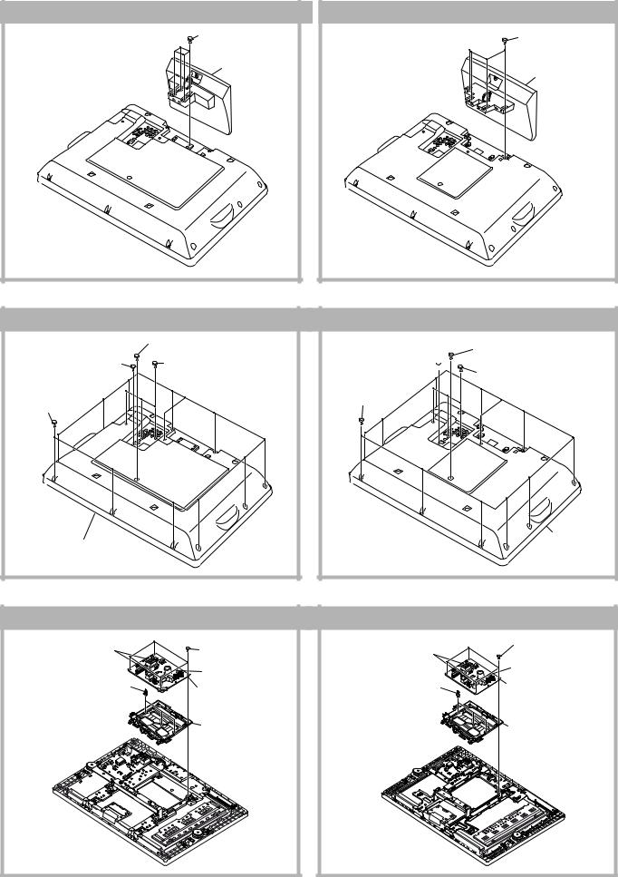
3-1. Stand Assy Removal |
|
|
|
(KLV-26T400) |
(KLV-32T400) |
|
|
|
1 Four screws |
1 |
Four screws |
|
(+PSW 5 X 16) |
||
|
|
(+PSW 5 X 16) |
|
|
|
|
|
|
2 Stand assy |
|
|
|
|
|
2 Stand assy |
3-2. Rear Cover Removal
(KLV-26T400)
|
3 One screw |
|
2 One screw |
(PSW 5 X 8) |
|
4 Three screws |
||
(+PSW M3 X 5) |
(+BVTP 3 X 12)
1 Twelves screws (BVTP2 4 X 16)
5 Lift to remove Rear Cover
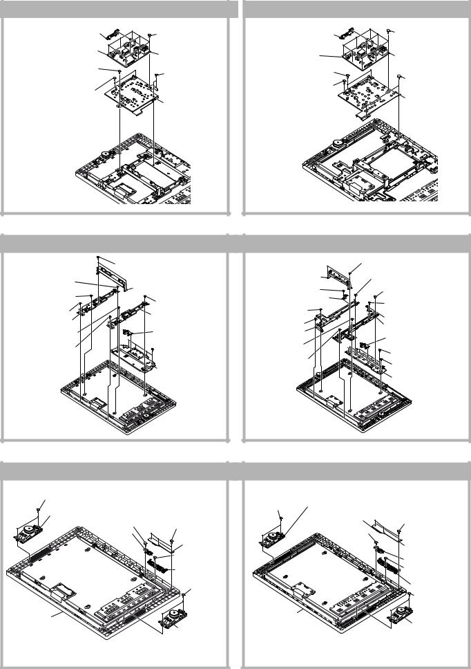
3-3. GPT Board and Bracket Removal
(KLV-26T400)
2 Two connectors |
1 Four screws |
CN6201 and CN6202 |
|
|
(+PSW 3SG) |
|
3 One connector |
|
CN6102 |
5 Three holder |
4 GPT board |
|
PC board |
||
|
(KLV-32T400)
2 One screw
3 One screw
(+PSW M3 X 5) 
(PSW 5 X 8)
4 Three screws (+BVTP 3 X 12)
1 Twelves screws (BVTP2 4 X 16)
5 Lift to remove Rear Cover
(KLV-32T400) |
|
|
|
2 Two connectors |
|
1 Four screws |
|
CN6201 and CN6202 |
|
(+PSW 3SG) |
|
|
3 One connector |
||
5 Three holder |
|
CN6102 |
|
4 |
GPT board |
||
PC board |
|||
|
|
||
6 GPT bracket |
6 GPT bracket |
– 7 –
KLV-26T400A,T400G, 32T400A
RM-GA013
3-4. BT Board and Bracket Removal
(KLV-26T400)
4 Side Jack Bracket Assy |
1 Nine screws |
|
2 Five connectors |
(+BVST 3 X 8) |
|
|
||
CN2000, CN2004, CN3000, |
3 BT board |
|
CN3003, CN7000 |
||
|
6 One screw |
5 Two screws |
(+PSW M4 X 8) |
|
|
(+BVST 3 X 8) |
7 Two screws |
|
(BVTP2 4 X 16) |
|
|
8 Main Bracket |
(KLV-32T400) |
|
|
4 Side Jack Bracket Assy |
1 |
Nine screws |
2 Six connectors |
|
(+BVST 3 X 8) |
|
|
|
CN2000, CN2004, CN3000, |
3 |
BT board |
CN3003, CN7000 |
7 Two screws |
|
|
(BVTP2 4 X 16) |
|
|
6 One screw |
5 |
Two screws |
(+PSW M4 X 8) |
|
(+BVST 3 X 8) |
|
8 |
Main Bracket |
3-5. Vesa Frame Removal
(KLV-26T400)
|
1 Two screws |
|
3 One screw |
(+PSW M4 X 8) |
|
|
||
(+PSW M4 X 8) |
|
|
4 One screw |
2 Vesa top |
|
|
||
(+PSW M4 X 8) |
7 One screw |
|
5 One screw |
||
(+PSW M4 X 8) |
||
(BVTP2 4 X 16) |
||
q; Frame Spine (R) |
||
6 Frame, spine (L) |
||
|
||
8 One screw |
qa Bracket AC |
|
(+PSW M4 X 8) |
||
|
9 One screw
(BVTP2 4 X 16)  qs Four screws (BVTP2 4 X 16)
qd Frame Bottom
(KLV-32T400)
|
1 Two screws |
|
(+PSW M4 X 8) |
2 Vesa top |
5 Two screws |
3 One screw |
(+PSW M4 X 8) |
(+PSW M4 X 8) |
qa Two screws |
|
|
4 Vesa Frame (Bottom) (32L) |
(+PSW M4 X 8) |
6 One screw |
9 One screw |
(+PSW M4 X 8) |
(+PSW M4 X 8) |
7 One screw |
q; Vesa Frame (Bottom) (32R) |
|
(BVTP2 4 X 16) |
qf Frame Spine (R) |
|
8 Frame, spine (L) |
|
|
qs One screw |
qg Bracket AC |
|
(+PSW M4 X 8) |
|
|
qd One screw |
qh |
Four screws |
(BVTP2 4 X 16) |
|
(BVTP2 4 X 16) |
|
qj |
Four screws |
|
|
(+PSW M4 X 8) |
qk Frame Bottom
3-6. HT Board and Speaker Removal
(KLV-26T400) |
|
|
(KLV-32T400) |
|
|
|
1 Two screws |
|
|
1 Two screws |
|
|
|
(BVTP2 4 X 16) |
|
|
2 Loudspeaker |
|
|
|
|
|
(BVTP2 4 X 16) |
|
|
||
|
|
|
|
|
||
2 Loudspeaker |
7 One screw |
|
|
(5.5 X 12cm) |
|
|
|
|
6 One connector |
|
|
||
(5.5 X 12cm) |
|
|
5 Three screws |
|||
(BVTP2 3 X 12) |
5 Three screws |
|
||||
|
|
8 One screw |
|
(BVTP2 3 X 12) |
||
|
8 Guide Light |
|
|
|||
|
(BVTP2 3 X 12) |
|
(BVTP2 3 X 12) |
|
||
|
|
|
|
|||
|
|
|
|
|
||
|
|
6 HT board |
|
|
7 HT board |
|
|
|
9 One screw |
|
|
9 Guide Light |
|
|
|
(BVTP2 3 X 12) |
|
|
||
|
|
|
|
|
|
|
|
|
0 Control Button |
|
|
q; |
One screw |
|
|
|
|
|
(BVTP2 3 X 12) |
|
|
|
3 Two screws |
|
|
|
|
|
|
|
|
|
qa Control Button |
|
|
|
(BVTP2 4 X 16) |
|
|
|
|
|
|
|
|
|
|
|
|
|
|
|
|
|
3 Two screws |
|
|
|
|
|
|
(BVTP2 4 X 16) |
qa Bezel assy |
|
|
qs Bezel assy |
|
|
|
|
|
|
|
|
|
|
|
|
4 Loudspeaker |
|
|
|
4 Loudspeaker |
|
|
|
|
|
(5.5 X 12cm) |
|
|
|
(5.5 X 12cm) |
|
|
|
|
|
|
|
|
|
|
|
|
|
|
– 8 – |
|
|
|
KLV-26T400A,T400G, 32T400A
RM-GA013
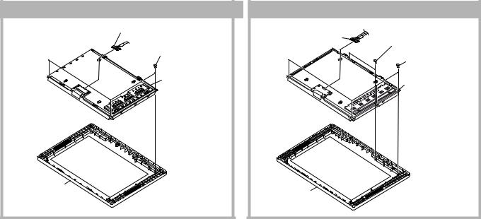
3-7. LCD Panel and Bezel Assy Removal
(KLV-26T400) |
(KLV-32T400) |
2 Harness |
3 Harness |
with connector |
with connector |
|
1 Two screws |
1 Three screws |
(BVTP2 4 X 16) |
|
|
(BVTP2 4 X 16) |
2 Four screws |
|
(BVTP2 4 X 16) |
3 LCD panel |
4 LCD panel |
|
4 Bezel assy
5 Bezel assy
– 9 –
KLV-26T400A,T400G, 32T400A
RM-GA013
SECTION 4
WIRE DRESSING
CAUTION :
1. Do not overpull the wires during dressing --> avoid disconnection of wires.
2. Make sure wires are kept away from sharp edges, heatsinks & other high-temperature parts.
4.1 (KLV-26T400)
Legend:
Hook
4-1-1. Wire Dressing overview for Non-CISPR model.
4-1-2. Wire Dressing overview for CISPR model.
4-1-3. Wire Dressing overview for 26T400G model.
4-1-5. Dressing of Connector Assy 10P
Attach Tape, LCD (X1) to Connector Assy 10P as shown.
Use datum lines shown as an indication for attaching Tape, LCD to Connector Assy 10P
Tape, |
LCD |
4-1-4. Dressing of Connector Assy 1P
1)Insert Connector Assy 1P to HT PWB's screw hole and panel's screw hole as shown.
2)Attach Sheet Core, C (X1) to panel at location of Connector Assy 10P.
|
|
|
Attach Sheet Core, |
1 |
Conn Assy 1P |
2 |
C to panel |
|
|
HT PWB
– 10 –

KLV-26T400A,T400G, 32T400A
RM-GA013
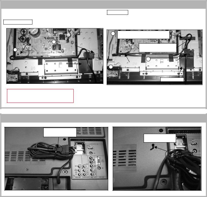
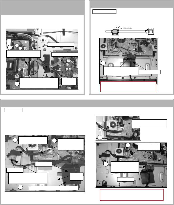
4-1-6. AC Power Cord Wire Dressing (Before installing G1 Bracket with GPT PWB)
Non-CISPR model
1)Install AC cord holder to AC power cord at specified position as shown.
CISPR model
1)Install Ferrite core to AC power cord at specified position as shown
2)Next, install AC cord holder to AC power cord at specified position.
1 AC Cord Holder
400 ± 5mm
Caution: |
Attach Sheet Core, C (X2) to |
|
AC Power Cord |
||
Do not cover the |
||
|
||
screw holes |
|
|
with the Sheet Core, C |
|
Use edge of Inverter board's cover and AC power cord connector as a guideline for placement of power cord
CAUTION:
1.Ensure that AC power cord is not stressed whilst inserting it into AC cord bracket.
|
|
360± 5mm |
|
2 AC Cord Holder |
|
|
|
|
510 ± 5mm |
1 |
Ferrite Core |
|
|
||
|
|
|
|
|
2. Attach Sheet Core, C (X2) to |
||
Caution: |
AC Power Cord. Make sure both |
||
Do not cover the |
Sheet Core, C overlaps the two |
||
screw holes with the |
|
|
|
Sheet Core, C |
|
|
|
1. Attach Tape, Shield to AC Power Cord (X2)
Use edge of Inverter board's cover and AC power cord connector as a guideline for placement of power cord
CISPR models only
Attach Tape, Shield to AC Power Cord (X2)
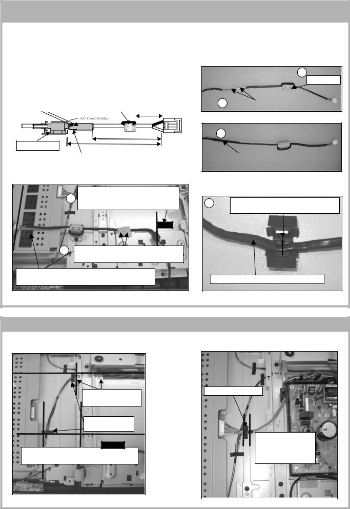
4-1-7. Conn Assy 10P Dressing (Before installing G1 Bracket with GPT PWB)
Dress Conn Assy 10P below Spine, Frame.
Next, attach Tape, LCD (X2) to Conn Assy 10P as shown.
Attach Tape, LCD (X2) to Conn Assy 10P |
Dress Conn Assy |
10P underneath |
Spine, Frame |
Ensure Conn Assy |
10P passes through |
the slot on main |
bracket |
– 11 –
KLV-26T400A,T400G, 32T400A
RM-GA013
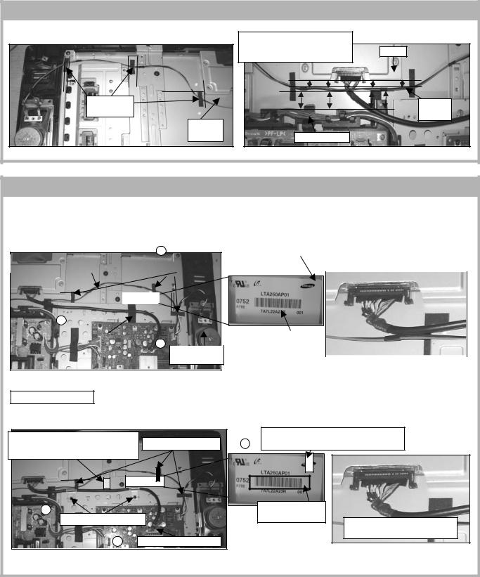
4-1-7. SP Connector Assy 4P Dressing for 26T400A
SP Connector Assy 4P wire dressing for 26T400A model as below.
Attach Tape,
LCD (3X)
SP Conn
Assy 4P
Keep distance between SP Conn
Assy 4P and:
T-CON
T-CON, Conn Assy 14P
SP Conn |
Assy 4P |
Conn Assy 14P |
4-1-8. LVDS Harness and SP Connector Assy 4P Dressing
See steps below for LVDS harness and SP Connector Assy 4P wire dressing.
|
KLV-26T400A Non-CISPR model |
|
|
|
|
|
|
|
|
|
|
|
|
|
||
|
|
|
|
|
|
|
|
|
|
|
|
|
|
|
|
|
|
|
|
|
|
|
|
|
|
|
|
|
|
|
|
||
|
|
|
|
|
|
|
|
|
|
When attaching Tape, LCD, ensure that it |
|
|||||
|
|
|
|
|
1 |
|
|
|
covers and hides the SAMSUNG logo |
|
||||||
|
Make sure SP Conn Assy 4P is above this |
Attach Tape, LCD |
|
|
|
|
|
|
|
|
||||||
|
area as Vesa Frame will be assembled later |
|
|
|
|
|
|
|
|
|||||||
|
|
|
|
|
|
(X3) |
|
|
|
|
|
|
|
|
||
|
|
|
|
|
|
|
|
|
|
|
|
|
|
|||
|
|
|
|
|
|
|
|
|
|
|
|
|
|
|
|
|
|
|
|
|
|
|
|
|
|
|
|
|
|
|
|
|
|
|
|
|
|
|
|
|
|
|
|
|
|
|
|
|
|
|
|
|
|
|
|
|
|
|
|
|
|
|
|
|
|
|
|
|
|
|
|
|
|
|
|
|
|
|
|
|
|
|
|
|
3
Attach Sheet Core, C |
|
|
|
Be careful not to cover the |
|
|
|
|
|
|
Make sure LVDS harness is fully |
|
|||||
to LVDS harness |
2 |
|
|
bar code |
|
|
|
|
|
|
|
inserted in direction as shown |
|
||||
|
|
Connect LVDS |
|
|
|
|
|
|
|
|
|
|
|
|
|
||
|
|
|
|
|
|
|
|
|
|
|
harness |
|
|
|
|
|
|
Note: When inserting LVDS harness to panel, make sure it is fully inserted and in the correct direction as shown.
26T400A CISPR model
See steps below for LVDS harness and SP Connector Assy 4P wire dressing.
Make sure SP Conn Assy 4P is above |
Attach Tape LCD (X3) |
1 |
this area as Vesa Frame will be |
||
assembled later |
|
|
3 |
|
|
Screw earth clamps (X2) |
|
|
2 |
Connect LVDS harness |
|
When attaching Tape, LCD, ensure that it covers and hides the SAMSUNG logo
Be careful not to
cover the bar code
Make sure LVDS harness is fully inserted with direction as shown
Note: When inserting LVDS harness to panel, make sure it is fully inserted and in the correct direction as shown.
– 12 –

KLV-26T400A,T400G, 32T400A
RM-GA013
4-1-9. SP Connector Assy 4P Dressing for KLV-26T400G
SP Connector Assy 4P wire dressing for 26T400G model as below.
SP Conn Assy |
4P |
Attach Tape, LCD (3X) |
Keep distance between SP |
T-CON |
|
Conn Assy 4P and: |
||
|
||
T-CON, Conn Assy 14P |
|
|
|
SP Conn Assy |
|
|
4P |
|
Conn Assy 14P |
|
4-1-10 LVDS Harness and SP Connector Assy 4P Dressing for KLV-26T400G |
||||
See steps below for LVDS harness and SP Connector Assy 4P wire dressing. |
When attaching Tape, LCD, ensure that it covers |
|||
|
|
|
|
|
Make sure SP Conn Assy 4P is above |
|
|
and hides the SAMSUNG logo |
|
|
Attach Tape LCD (X3) |
|
||
this area as Vesa Frame will be |
1 |
|
||
|
assembled later |
|
|
|
|
|
|
|
|
3 |
Attach Sheet Core, C |
|
|
|
to LVDS harness |
|
|
|
|
|
|
|
|
|
|
|
2 |
Connect LVDS harness |
Be careful not to cover |
|
|
|
|
the bar code |
Caution: Dress wires downward towards the panel and bezel. |
|
|||
|
Ensure capacitor does not touch tweeter or any conductive parts. |
|
||
|
|
|
|
Make sure LVDS harness is fully |
|
|
|
|
inserted with direction as shown |
|
4 |
|
5 |
|
|
|
|
Note: When inserting LVDS harness to panel, |
|
|
Attach Tape LCD (X1) |
|
Attach Tape LCD (X1) |
|
|
|
make sure it is fully inserted and in the |
||
|
to wire and panel |
|
to wire and panel |
correct direction as shown. |
4-1-11. Dressing of Connector Assy 14P
Dress Connector Assy 14P into G1 bracket's hook (4X) as shown.
Dress Conn Assy 14P into
G1 bracket's hook (4X)
4-1-12. Dressing of Connector Assy 14P,
Connector Assy 13P and Connector
Assy 10P
1)Dress Connector Assy 13P into G1 bracket's hook as shown.
2)Align Connector Assy 14P and Connector Assy 13P together and dress them using Sheet Core, C.
Common for all 26T400 models
Connector Assy 14P
Connector Assy 13P
Connector Assy 10P
Dress Conn Assy 14P and 2 Conn Assy 13P using Sheet,
1 Dress Conn Assy 13P into G1 bracket's hook (1X)
– 13 –
KLV-26T400A,T400G, 32T400A
RM-GA013
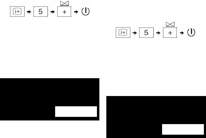
4-1-13. AC Power Cord Wire Dressing
1)Install the AC power cord with holder into AC cord bracket.
2)Dress the AC power cord wire pin, wire A6101.
Non-CISPR model
Dress AC power cord |
|
|
|
||
with pin, wire A6101 |
|
|
|
||
1 |
Install AC power cord with |
||||
|
|
||||
|
|
||||
|
|
|
holder into AC cord bracket |
||
2 |
|
|
|
|
|
|
|
|
|||
|
AC cord bracket |
|
|||
CISPR model
1)Install the AC power cord with holder into AC cord bracket.
2)Dress the AC power cord using Sheet Core, C on to main bracket.
3)Dress the AC power cord wire pin, wire A6101.
2 Dress AC Power Cord using Sheet Core, C on to Main Bracket
No need to attach Sheet
Core, C here
|
1 |
Install AC power |
|
|
|
|
cord with holder |
3 |
Dress AC power cord |
|
into AC cord |
with pin, wire A6101 |
|
bracket |
|
|
|
||
AC cord bracket
CAUTION:
1.Ensure that AC power cord is not stressed whilst inserting it into AC cord bracket.
4-1-14. AC Power Cord Wire Dressing at Rear Cover
Tie the root of the AC plug.
Hook the AC-band to the rear cover.
– 14 –

4.2 (KLV-32T400)
4-2-1. Wire Dressing overview for Non-CISPR model.
4-2-3. Dressing of Connector Assy 1P
1)Insert Connector Assy 1P to HT PWB's screw hole and bracket bottom's screw hole as shown.
2)Attach Sheet Core, C (X1) to panel at location of Connector Assy 10P.
|
|
|
|
Conn Assy 10P |
|
Use dowel |
|
|
Attach |
is above Conn |
|
1 |
2 |
Sheet |
Assy 1P |
||
as guide to |
Core, C to |
|
|||
attach Conn |
|
|
|
||
Conn Assy 1P |
pane |
|
|||
Assy 1P |
45º |
||||
|
|||||
|
|
|
|
Bracket, |
|
|
|
HT PWB |
|
Bottom |
|
|
|
|
|
||
KLV-26T400A,T400G, 32T400A
RM-GA013
4-2-2. Wire Dressing overview for CISPR model.
4-2-4. SP Connector Assy 4P Dressing
1) See steps 1 ~ 3 below for SP Connector Assy 4P wire dressing.
Use datum lines as reference |
Use datum lines as reference |
|
|
|
Use datum lines |
1 |
as reference |
|
|
Attach Tape, LCD (3X). |
|
Ensure wires go around |
|
inverter board. |
|
SP Conn Assy 4P is below Frame, Spine |
|
|
SP Conn Assy 4P |
2 |
Use datum line as reference |
Use datum lines as reference |
|
3 |
Attach Tape, LCD (2X) |
|
|
SP Conn Assy 4P |
|
is below Frame, |
|
Spine |
|
– 15 –
KLV-26T400A,T400G, 32T400A
RM-GA013
4-2-5. AC Power Cord Wire Dressing (Before
installing G1 Bracket with GPT PWB) for CISPR Models.
1)Install Ferrite core to AC power cord at specified position as shown.
2)Attach Tape, Shield (X2) on to specified position.
3)Next, wrap Sheet Core, E around area of Tape, Shield on AC power cord, to cover it.
4)Finally, install AC cord holder to AC power cord at specified position.
5)Attach Tape, Shield to AC power cord (X2) at specified position.
6) Attach Sheet Core, C to overlap the two Tape, Shields. |
1 |
Ferrite Core
This is to prevent the Tape, Shields from peeling off.
|
|
|
|
|
|
|
|
2 |
Tape, Shield (X2) |
|
Tape, Shield (X2) |
|
|
|
Ferrite Core |
||||||
|
140± 5mm |
|
||||||||
|
|
|
|
|
|
|
|
|
||
|
|
|
|
|
|
|
|
|
|
|
|
|
|
|
|
|
|
|
|
|
|
|
|
|
|
|
|
|
|
|
|
|
|
285± 5mm |
3 |
AC Cord Holder |
360 ± 5mm |
|
|
|
|
|
Wrap Sheet Core, E around area of Tape, |
Sheet Core, E |
|
|
|
|
Shield on AC Power Cord, to Cover it |
|
|
|
|
|
|
CISPR models only
6 Attach Sheet Core, C to Tape, Shields. Make sure it overlaps the Tape, Shields.
5 |
CISPR models only |
Attach Tape, Shield to AC Power Cord (X2)
Use edge of Inverter board's cover and AC power cord connector as a guideline for placement of power cord
4When installing AC cord holder, make sure the Sheet Core, E area is clamped as well
Portion of AC Power Cord with Sheet Core, E
4-2-6. Dressing of Connector Assy 10P and 14P |
|
Attach Tape, LCD to Connector Assy 10P and Connector Assy 14P as shown. |
|
Dress Conn Assy 10P |
Attach Tape, LCD (1X) |
|
|
below Frame, Spine |
|
Attach Tape, LCD |
|
(2X) |
|
|
Use datum lines as an |
|
indication for attaching |
Use datum lines as an indication for attaching |
Tape, LCD to |
Tape, LCD to Connector Assy 10P |
Connector Assy 14P |
– 16 –

KLV-26T400A,T400G, 32T400A
RM-GA013
4-2-7. LVDS Harness Dressing
See steps below for LVDS harness and SP Connector Assy 4P wire dressing.
|
|
|
|
|
|
|
|
|
|
|
|
|
|
|
|
|
|
|
|
|
|
|
|
Non-CISPR model |
|
|
|
|
|
|
|
|
|||||
|
|
|
|
|
|
|
|
|
|
|
|
|
|
|
||||
|
|
|
|
|
|
|
|
|
|
Attach Sheet Core, C |
|
|||||||
|
|
|
|
|
|
|
|
|
|
|
to LVDS harness. |
|
||||||
|
|
|
|
|
SP Conn Assy 4P below |
|
|
|
|
|
|
|
|
|
|
|
||
|
|
|
|
|
|
|
|
|
|
|
|
|
|
|||||
|
|
|
|
|
LVDS harness |
|
|
|
|
|
|
|||||||
|
|
|
|
|
|
|
|
|
|
|
|
|
|
|
||||
|
|
|
|
|
|
|
|
|
|
|
|
|
|
|
|
|
|
|
|
|
OK |
|
|
|
|
|
|
|
|
|
LVDS harness |
|
|||||
|
|
|
|
|
|
|
|
|
|
|
|
|
|
|
|
|
|
|
|
|
|
|
|
|
|
|
|
|
|
|
|
|
|
|
|
|
|
|
|
|
|
|
|
|
|
|
|
|
|
|
|
|
|
|
|
|
|
|
|
|
|
|
|
|
|
|
|
|
|
|
CN3000 |
|
|
|
|
|
|
|
|
|
|
|
|
|
|
|
|
|
|
|
|
|
|
|
|
|
|
|
|
|
|
|
|
|
|
|
|
|
|
||||
|
|
|
|
|
|
|
|
|
|
|
|
|
|
|
|
|
|
|
|
|
|
|
|
CISPR model |
|
|
|
|
|
|
|
|
|
|
|
|
|
|
|
|
|
|
|
|
|
|
|
|
|
|
|
|
||||
|
|
|
|
|
|
|
|
|
|
|
|
|
|
|
||||
|
|
|
|
|
|
|
|
|
|
|
Screw earth clamps |
|
|
|||||
|
|
|
|
|
|
|
|
|
|
|
|
(2X) |
|
|
||||
|
|
|
|
|
|
|
|
|
|
|
||||||||
|
|
|
|
|
|
|
|
|
|
|
|
|
|
|
|
|
|
|
|
|
|
|
|
SP Conn Assy 4P below |
|
|
|
|
|
|
|
|
|
|
|||
|
|
NG |
|
|
LVDS harness |
|
|
|
|
|
||||||||
|
|
|
|
|
|
|
|
|
|
|
|
|
|
|
|
|
|
|
|
|
|
|
|
|
|
|
|
|
|
|
|
|
|
|
|
|
|
|
|
|
|
|
|
|
|
|
|
|
|
|
|
|
||||
|
|
|
|
|
|
|
|
|
|
|
|
|
||||||
Note: When inserting LVDS harness to panel, make sure it is |
|
|
|
|
|
|
|
|
|
|||||||||
|
|
|
|
|
|
|
LVDS harness |
|
||||||||||
|
|
fully inserted and in the correct direction as shown. |
|
|
|
|
|
|
|
|
|
|
|
|
|
|
||
|
|
|
|
|
|
|
|
|
|
|
|
|
|
|
|
|||
|
|
|
|
|
|
|
|
|
|
|
|
|
CN3000 |
|
|
|
|
|
|
|
|
|
|
|
|
|
|
|
|
|
|
|
|
|
|
|
|
|
|
|
|
|
|
|
|
|
|
|
|
|
|
|
|
|
|
|
4-2-8. Dressing of Connector Assy 10P and Connector Assy 14P on G1 Bracket
1) Dress Connector Assy 10P into G1 bracket's hook (1X) as shown. 2) Next, dress Connector Assy 14P into G1 bracket's hook (4X).
Keep distance between Conn |
|
Dress Conn Assy |
Assy 10P and SP Conn Assy 4P |
1 |
10P into G1 bracket's |
|
|
hook (1X) |
|
|
2 Dress Conn Assy 14P into G1 bracket's hook (4X) |
Conn Assy 10P is below G1 bracket |
||
– 17 –
KLV-26T400A,T400G, 32T400A
RM-GA013
4-2-9. Dressing of Connector Assy 14P,
Connector Assy 13P and Connector
Assy 10P
1)Dress Connector Assy 13P into G1 bracket's hook as shown.
2)Align Connector Assy 14P, Connector Assy 10P and Connector Assy 13P together and dress them using Sheet Core, C.
1 |
|
Connector Assy 14P |
||
|
|
|
||
Dress Conn Assy 13P into |
Connector Assy 13P |
|||
G1 bracket's hook (1X) |
||||
|
|
|||
|
Dress Conn Assy 14P, Conn |
Connecto |
||
2 |
Assy, 10P and Conn Assy 13P |
Assy 10P |
||
|
using Sheet, Core, C |
|
||
4-2-10. AC Power Cord Wire Dressing
Non-CISPR model
1)Install AC cord holder to AC power cord at specified position as shown.
2)Then install the AC power cord with holder into AC cord bracket.
1
80 ± 5mm
2
Install AC power cord with
holder into AC cord bracket AC cord bracket
CAUTION:
1.Ensure that AC power cord is not stressed whilst inserting it into AC cord bracket.
4-2-11. AC Power Cord Wire Dressing
CISPR model
1)Attach Sheet Core, C to Vesa Frame Bottom (32).
2)Insert AC power cord into CN6102.
3)Install the AC power cord with holder into Bracket, AC.
4)Then, install Bracket, AC into Bracket, Bottom.
5)Attach Sheet Core, C to Ferrite Core.
6)Lastly, dress AC power cord using pin, wire A6101 as shown.
5 |
Attach Sheet Core, C |
6 |
Dress AC power |
|
|
to Ferrite Core |
|||
|
|
|
|
cord using pin, wire |
|
|
|
|
A6101 |
|
|
Bracket, AC |
|
|
Ferrite, Core |
|
|
|
|
AC Cord that is looped around |
|
Bracket, |
||
Ferrite Core is inserted under |
|
Bottom |
||
|
Frame, Spine |
|
|
|
|
4 |
Install Bracket, AC into Bracket, Bottom |
||
Attach Sheet Core, C to Vesa Frame Bottom (32)
1
2Insert AC power cord to CN6102.
3 Install AC power cord with holder into
Bracket, AC
Bracket, AC 
CAUTION:
1.Ensure that AC power cord is not stressed whilst inserting it into AC Cord bracket.
– 18 –

KLV-26T400A,T400G, 32T400A
RM-GA013
4-2-12. AC Power Cord Wire Dressing at Rear Cover
Tie the root of the AC plug.
Hook the AC-band to the rear cover.
– 19 –
KLV-26T400A,T400G, 32T400A
RM-GA013
SECTION 5
SERVICE ADJUSTMENTS
5-1. Accessing Diagnostic Menu
5-3. Control keys via Remote Commander.
1.While TV set on standby, press the following sequence on the Remote commander (RMGA013).
Buttons on the Remote Commander to access the service menu items and adjust the data values.
On screen |
|
Channel 5 |
|
|
|
|
|
POWER |
|
|
Volume (-) |
|
|||||
|
|
|
||||||
|
|
|
||||||
|
|
|
||||||
|
|
|
||||||
|
|
|
||||||
display |
|
|
|
|
|
|
|
|
|
|
|
|
|
|
|
|
|
The following menu will appear on the screen
|
MAIN_POWER_ERROR |
|
0 |
|
|
5V_POWER_ERROR |
|
0 |
|
|
AUDIO_ERROR |
|
0 |
|
|
BALK_LIGHT_ERROR |
|
0 |
|
|
TEMP_ERROR |
|
0 |
|
|
|
|
|
|
Figure 1
2.To quit the diagnostic menu, turn off and on the set.
5-2. Viewing the Service Mode Display
1.While TV on standby mode, press the following sequence on the Remote commander.
On screen |
|
|
|
|
|
|
|
|
|
Channel 5 |
|
Volume (+) |
|
POWER |
|||
|
|
|
||||||
|
|
|
||||||
|
|
|
||||||
display |
|
|
|
|||||
|
|
|
|
|
|
|
|
|
|
|
|
|
|
|
|
|
|
(if wrong key is pressed or passed 3 seconds during each process, cancel entering the self-diagnosis display.)
5-4. Adjustment Method
5-4-1. Aging
1.While TV on standby mode, press the following sequence on the Remote commander.
On screen |
|
|
|
|
|
|
|
|
|
Channel 5 |
|
Volume (+) |
|
POWER |
|||
|
|
|
||||||
|
|
|
||||||
|
|
|
||||||
display |
|
|
|
|||||
|
|
|
|
|
|
|
|
|
|
|
|
|
|
|
|
|
|
Example on screen display: |
|
|
|
|
|
|
|
|
2. Select AGING with 2or 5On the Remote Commander. |
|||||||
|
|
Categry Item |
|
|
|
|
|
|
|
|
|
|
|
|
3. |
Select AGING MODE with 1 or 4 On the Remote |
|
|
[Category/Item name] Within 17 |
|
|
|
[Data] Within 7 characters |
|
Commander. |
||||||||
|
|
|
|
|
|
|
||||||||||
|
|
|
characters |
|
|
|
|
|
|
|
|
|
|
|
|
|
T |
V |
|
|
|
|
|
|
|
|
S E |
R V |
I |
C |
E |
4. |
Select data value with 3 or 6 On the Remote |
0 |
0 0 |
W B |
|
|
|
M E |
|
|
|
|
|
|
|
|
|
Commander to 1 to enable. Refer to Service Items |
0 0 0 |
W P R _ C |
|
|
|
|
|
|
2 5 5 |
|
|
|
|
(Table 1) page 17 |
|||
|
L O C T O P |
P R O G R A M : |
T M 0 . 0 7 |
0 |
|
|
|
5. Press <I/1> to exit. |
||||||||
|
|
|
|
6. |
When exit it will have the new data value and start aging. |
|||||||||||
|
|
|
G |
T |
V |
: |
M |
R |
1 . |
0 . |
2 |
|
|
|
||
|
|
|
N |
V |
M |
: |
T |
D |
0 . |
1 0 |
0 |
|
|
|
7. |
Aging condition: |
|
|
|
|
|
|
|
|
|
|
|
|
|
|
|
|
a) Supply voltage : Rating |
|
|
|
|
|
|
PROGRAM: Show the Application version |
|
|
|
|
b) Time: More than 20 minutes |
|||||
|
|
|
|
|
|
GTV: Show the GTV Library version |
|
|
|
|
|
|||||
|
|
|
|
|
|
NVM: Show the NVM version in the NVM data |
|
|
|
c) Ambient Temp: 22-28 degrees |
||||||
|
|
|
|
|
|
(4bytes ASCII data) |
|
|
|
|
|
|
|
|||
|
|
|
|
|
|
|
|
|
|
|
|
|
|
|
|
d) Input : Set no signal except digital and analog |
|
|
|
|
|
|
|
|
|
|
|
|
|
|
|
|
RF(Video/Component/PC) |
|
|
|
|
|
|
|
|
|
|
|
|
|
|
|
Example on screen display: |
|
2.To reset, press 8 – 0 –  .
.
3.To Exit, press the <I/1> key .
T |
V |
|
|
|
|
|
|
S |
E R V I C E |
||
0 |
0 |
0 |
A G I N G |
|
|
|
|
|
|
|
|
|
|
|
|
|
|
|
|
|
|
||
0 |
0 |
0 |
A G I N G |
M O D E |
|
|
1 |
|
|
|
|
|
L O C T O P |
|
|
|
|
|
|
||||
|
P R O G R A M : |
T M 0 . 0 |
7 0 |
|
|
||||||
|
|
|
|
G T V |
: |
M R 1 . 0 . 2 |
|
|
|||
|
|
|
|
N V M |
: |
T D 0 . 1 |
0 0 |
|
|
||
|
|
|
|
|
|
|
|
|
|
|
|
PROGRAM: Show the Application version GTV: Show the GTV Library version
NVM: Show the NVM version in the NVM data (4bytes ASCII data)
– 20 –
5-4-2. Resetting the User MenuFactory Reset
1.While TV on standby mode, press the following sequence on the Remote commander.
On screen |
|
|
|
|
|
|
|
|
|
Channel 5 |
|
Volume (+) |
|
POWER |
|||
|
|
|
||||||
|
|
|
||||||
|
|
|
||||||
display |
|
|
|
|||||
|
|
|
|
|
|
|
|
|
|
|
|
|
|
|
|
|
|
2.Select SERVICE with 2 or 5 On the Remote Commander.
3.Select AUTO SET FACTORY with 1or 4On the Remote Commander.
4.Select data value with 3 or 6 On the Remote Commander to 0 to current condition. Refer to Service Items (Table 1) page 17
5.Press <I/1> to exit.
Example on screen display:
T |
V |
|
|
|
|
|
|
|
S |
E R V I C E |
||
0 |
0 |
0 |
S E R V |
I C E |
|
|
|
|
|
|
|
|
|
|
|
|
|
|
|
|
|
|
|||
0 |
0 |
0 |
A U T O G S E T |
F A C T O R Y |
|
0 |
|
|
|
|||
|
L O C T O P |
|
|
|
|
|
|
|
||||
|
|
P R O G R A M : |
T M 0 . 0 |
7 0 |
|
|
||||||
|
|
|
|
|
G T V |
: |
M R 1 . 0 . 2 |
|
|
|||
|
|
|
|
|
N V M |
: |
T D 0 . 1 0 0 |
|
|
|||
|
|
|
|
|
|
|
|
|
|
|
|
|
PROGRAM: Show the Application version GTV: Show the GTV Library version
NVM: Show the NVM version in the NVM data (4bytes ASCII data)
KLV-26T400A,T400G, 32T400A
RM-GA013
5-4-3. White Balance Adjustment
Test Pattern:
a)Connect video signal of white to video input
b)Restort to original value : Color temp=0, Picture=Max,Brightness=50,Backlight=max
1.While TV on standby mode, press the following sequence on the Remote commander.
On screen |
|
|
|
|
|
|
|
|
|
Channel 5 |
|
Volume (+) |
|
POWER |
|||
|
|
|
||||||
|
|
|
||||||
|
|
|
||||||
display |
|
|
|
|||||
|
|
|
|
|
|
|
|
|
|
|
|
|
|
|
|
|
|
2.Select WB with 2 or 5 On the Remote Commander.
3.Select WPR_C with 1or 4On the Remote Commander.
4.Select data value with 3 or 6 On the Remote Commander.
5.Press <I/1> to exit.
Note: Refer to Service Items (Table 1) page 17 for other item and data value.
Example on screen display:
T |
V |
|
|
|
|
|
|
S |
E |
R V I C E |
||
0 |
0 |
0 |
W B |
|
|
|
|
|
|
|
|
|
|
|
|
W P R _ C |
|
|
|
|
|
|
|
|
|
0 |
0 |
0 |
|
|
|
|
2 |
5 |
5 |
|
|
|
|
|
|
|
|
|
|
|
|
|
|
|
|
|
L O C T O P |
P R O G R A M : |
T M 0 . 0 |
7 0 |
|
|
||||||
|
|
|
|
G T V |
: |
M R 1 . 0 . 2 |
|
|
||||
|
|
|
|
N V M |
: |
T D 0 . 1 |
0 |
0 |
|
|
||
|
|
|
|
|
|
|
|
|
|
|
|
|
PROGRAM: Show the Application version GTV: Show the GTV Library version
NVM: Show the NVM version in the NVM data (4bytes ASCII data)
– 21 –
KLV-26T400A,T400G, 32T400A |
|
|
|
|
|
|
|
|||
|
|
RM-GA013 |
|
|
|
|
|
|
|
|
|
5-5. Table 1 |
|
|
|
|
|
|
|
|
|
|
|
|
|
|
|
|
|
|
|
|
|
Category |
Item |
Description |
|
Remarks |
bit |
Min |
Max |
Initial |
|
|
|
|
|
|
|
|
|
|
|
|
|
|
WPR C |
W/B R adjustment for Cool |
Change color temperature to Cool |
8 |
0 |
255 |
ADJ value |
|
|
|
|
|
|
|
|
|
|
|
||
|
|
WPG C |
W/B G adjustment for Cool |
|
|
8 |
0 |
255 |
ADJ value |
|
|
|
|
|
|
|
|
|
|
|
|
|
|
WPB C |
W/B B adjustment for Cool |
|
|
8 |
0 |
255 |
ADJ value |
|
|
|
|
|
|
|
|
|
|
|
|
|
|
WPR N |
W/B R adjustment for Cool |
|
|
8 |
0 |
255 |
ADJ value |
|
|
|
|
|
Change color temperature to Neautral |
|
|
|
|
|
|
|
|
WPG N |
W/B G adjustment for Cool |
8 |
0 |
255 |
ADJ value |
|
||
|
|
|
|
|
||||||
|
|
|
|
|
|
|
|
|
|
|
|
WB |
WPB N |
W/B B adjustment for Cool |
|
|
8 |
0 |
255 |
ADJ value |
|
|
|
|
|
|
|
|
|
|
|
|
|
|
WPR W1 |
W/B R adjustment for Warm1 |
|
|
8 |
0 |
255 |
ADJ value |
|
|
|
|
|
Change color temperature to Warm1 |
|
|
|
|
|
|
|
|
WPG W1 |
W/B G adjustment for Warm1 |
8 |
0 |
255 |
ADJ value |
|
||
|
|
|
|
|
||||||
|
|
|
|
|
|
|
|
|
|
|
|
|
WPB W1 |
W/B B adjustment for Warm1 |
|
|
8 |
0 |
255 |
ADJ value |
|
|
|
|
|
|
|
|
|
|
|
|
|
|
WPR W2 |
W/B R adjustment for Warm2 |
|
|
8 |
0 |
255 |
ADJ value |
|
|
|
|
|
Change color temperature to Warm2 |
|
|
|
|
|
|
|
|
WPG W2 |
W/B G adjustment for Warm2 |
8 |
0 |
255 |
ADJ value |
|
||
|
|
|
|
|
||||||
|
|
|
|
|
|
|
|
|
|
|
|
|
WPB W2 |
W/B B adjustment for Warm2 |
|
|
8 |
0 |
255 |
ADJ value |
|
|
|
|
|
|
|
|
|
|
|
|
|
|
|
"TV" system FIX. |
|
|
|
|
|
|
"0:Auto, 1:BG, 2:DK, |
|
|
TUNING SYSTEM |
|
|
3 |
0 |
0x08 |
0 |
3:I, 4:M, |
|
|
|
"Auto" or "BG" or "DK" or "I" or "M" |
|
|
||||||
|
|
|
|
|
|
|
|
|
5_:No use" |
|
|
|
|
|
|
|
|
|
|
|
|
|
|
|
|
|
|
|
|
|
|
|
|
|
NO SIGNAL MUTE |
When RF is no signal, select |
|
|
1 |
0 |
1 |
0 |
0:OFF, 1:ON |
|
|
ON/OFF of audio mute. |
|
|
||||||
|
|
|
|
|
|
|
|
|
|
|
|
|
|
|
|
|
|
|
|
|
|
|
|
|
|
|
|
|
|
|
|
0:current condition |
|
|
|
|
|
|
|
|
|
|
1:SOEM(NORTH) |
|
|
AUTOSET FACTORY |
Select a factory, and preset factory |
Refer to the followings and sheet |
3 |
0 |
0x08 |
0 |
2:SOEM(SOUTH) |
|
|
|
signal. |
"AUTOSET FACTORY" |
3:STT |
||||||
|
|
|
|
|
|
|
|
|
|
4:SSV |
|
|
|
|
|
|
|
|
|
|
5-:No use |
|
|
|
|
|
|
|
|
|
|
|
|
SERVICE |
|
|
This value is adjust by production. |
|
|
|
|
|
|
|
AGC |
Control of AGCOUT(66pin) of SMIC |
Initial value is adjustment value. |
8 |
0 |
0xFF |
ADJ value |
|
||
|
|
|
||||||||
|
|
|
|
AGC Take Over |
|
|
|
|
|
|
|
|
|
|
|
|
|
|
|
|
|
|
|
Forced 2D |
Select "2D" and "Current" |
|
|
1 |
0 |
0x01 |
0 |
0:Current, 1:2D |
|
|
|
|
|
|
|
|
|
|
|
|
|
|
|
Initial data is |
|
|
|
|
|
|
|
|
OVMADAPT |
FM over-moduration adaptation |
BG/DK/I |
: 1 |
1 |
0 |
0x01 |
current |
0:Disable |
|
|
M |
: 0 |
condition |
1:Enable |
|||||
|
|
|
|
|
|
|
||||
|
|
|
|
Radio |
: 1 |
|
|
|
|
|
|
|
|
|
|
|
|
|
|
|
|
|
|
|
|
Initial data is |
|
|
|
|
0:Narrow |
|
|
|
FILTBW |
Sound carrier filter bandwith. |
BG/DK/I |
: 1 |
2 |
0 |
0x03 |
current |
1:Extra wide |
|
|
M |
: 0 |
condition |
2:Medium |
|||||
|
|
|
|
|
|
|
||||
|
|
|
|
Radio |
: 1 |
|
|
|
|
3:Wide |
|
|
|
|
|
|
|
|
|
|
|
|
|
ADC |
AD auto calibration |
AD Cal. |
|
1 |
0 |
0x01 |
0 |
1:Start auto ADC |
|
|
|
|
|
|
|
|
|
|
|
|
|
SER1 |
Serial Number 1 |
SONY VERSION NO CHAR1 INDEX |
8 |
0 |
0xFF |
ADJ value |
|
|
|
|
|
|
|
|
|
|
|
|
|
|
|
SER2 |
Serial Number 2 |
SONY VERSION NO CHAR2 INDEX |
8 |
0 |
0xFF |
ADJ value |
|
|
|
|
|
|
|
|
|
|
|
|
|
|
|
SER3 |
Serial Number 3 |
SONY VERSION NO CHAR3 INDEX |
8 |
0 |
0xFF |
ADJ value |
|
|
|
|
|
|
|
|
|
|
|
|
|
|
PRODUCTION |
SER4 |
Serial Number 4 |
SONY VERSION NO CHAR4 INDEX |
8 |
0 |
0xFF |
ADJ value |
|
|
|
|
|
|
|
|
|
|
|
|
|
|
SER5 |
Serial Number 5 |
SONY VERSION NO CHAR5 INDEX |
8 |
0 |
0xFF |
ADJ value |
|
||
|
|
|
||||||||
|
|
|
|
|
|
|
|
|
|
|
|
|
SER6 |
Serial Number 6 |
SONY VERSION NO CHAR6 INDEX |
8 |
0 |
0xFF |
ADJ value |
|
|
|
|
|
|
|
|
|
|
|
|
|
|
|
SER7 |
Serial Number 7 |
SONY VERSION NO CHAR7 INDEX |
8 |
0 |
0xFF |
ADJ value |
|
|
|
|
|
|
|
|
|
|
|
|
|
|
|
SER8 |
Serial Number 8 |
SONY VERSION NO CHAR8 INDEX |
8 |
0 |
0xFF |
ADJ value |
|
|
|
|
|
|
|
|
|
|
|
|
|
|
|
AGING MODE |
Aging mode |
APRV_AGING_ENABLE_INDEX |
1 |
0 |
1 |
0 |
0:Disable |
|
|
|
1:Enable |
||||||||
|
|
|
|
|
|
|
|
|
|
|
|
|
|
|
|
|
|
|
|
|
|
|
|
AGING TIME |
Aging expire time |
APRV AGING TIME INDEX |
8 |
0 |
0xFF |
0 |
|
|
|
|
|
|
|
|
|
|
|
|
|
|
AGING |
|
|
|
|
|
|
|
|
0:Black |
|
|
|
|
|
|
|
|
|
|
1:White |
|
|
AGING COLOR |
Aging color |
APRV_AGING_COLOUR_INDEX |
8 |
0 |
0xFF |
0 |
2:Red |
|
|
|
|
|
|
|
|
|
|
|
3:Green |
|
|
|
|
|
|
|
|
|
|
4:Blue |
|
|
|
|
|
|
|
|
|
|
|
|
|
TEMP |
Read resister "TEMPERATURE" |
Same as NXP service mode |
8 |
0 |
0xFF |
current |
|
|
|
|
condition |
|
|||||||
|
STATUS |
|
|
|
|
|
|
|
|
|
|
|
|
|
|
|
|
|
|
|
|
|
SIG_BOOSTER_LEV |
Read A/D port for RF signal level |
A/D port: SARIN1 |
8 |
0 |
0xFF |
current |
|
||
|
|
|
||||||||
|
|
condition |
|
|||||||
|
|
|
|
|
|
|
|
|
|
|
|
|
|
|
|
|
|
|
|
|
|
5-6. Board & Panel Replacement
When replacing the BT board and Panel readjust
the W/B.
– 22 –
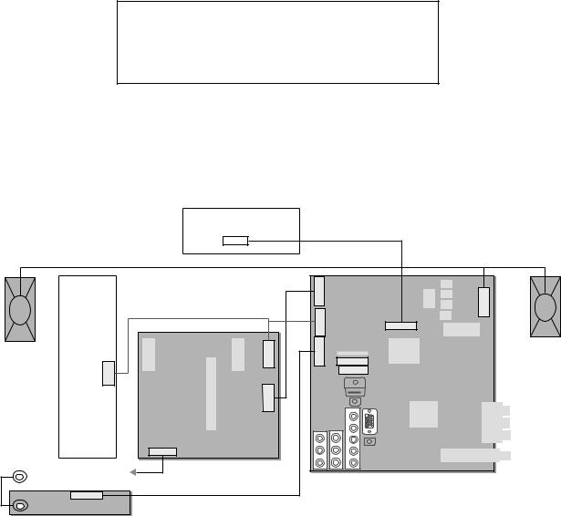
KLV-26T400A,T400G, 32T400A
RM-GA013
SECTION 6
DIAGRAMS
6-1. BLOCK DIAGRAM
Due to complexity of the board, performing component level field repairs are not recommended. Complete board replacement is required if service is necessary.
6-2. |
CONNECTOR DIAGRAM |
|
|
|
|
|
||
6-2-1 (KLV-26T400) |
|
|
|
|
|
|
||
|
|
|
|
T-CON |
|
|
|
|
|
|
|
|
CNF1(40) |
|
|
LVDS |
|
|
|
|
|
|
|
|
|
|
|
|
|
|
|
|
Speaker L, R |
|
|
|
|
|
|
Power, Standby, Audio VCC, Main VCC |
CN7000(11) |
|
|
|
|
|
|
|
|
|
|
||
|
|
|
|
|
|
CN7001(4) |
|
BT |
|
|
INVERTER |
24V, Inv Err, BL, Dimmer |
|
|
|
||
|
|
CN1(14) |
|
CN6201(8) |
CN3001(10) |
|
CN3000(40) |
|
|
Speaker R |
|
|
|
|
|
ECS |
|
|
|
|
|
|
|
CN3002(18) |
|
|
|
|
|
|
|
|
|
|
|
|
|
|
|
|
|
|
CN3003(4) |
|
|
|
|
GPT |
CN6202(13 |
) |
|
|
|
|
|
|
|
|
|
|
|
|
|
|
|
CN6102(3) |
|
|
|
|
|
|
|
|
AC Power |
|
|
|
|
|
Ground |
|
Key, SIRCS, LED |
|
|
|
|
|
|
|
|
|
|
|
|
|
|
|
|
|
CN1000(10) |
|
|
|
|
|
|
|
|
|
HT |
|
|
|
|
|
CN2000(4)
Speaker L
– 23 –
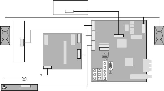
KLV-26T400A,T400G, 32T400A
RM-GA013
6-2-2 (KLV-32T400)
T-CON
LVDS
CNF1(40)
Speaker L, R
|
|
|
Power, Standby, Audio VCC, Main VCC |
CN7000(11) |
|
|
|
|
|
|
24V, Inv Err, BL, Dimmer |
|
BT |
|
|
|
INVERTER |
|
CN6202(13) CN6201(8) |
CN3001(10) CN7001(4) |
|
|
CN3000(40) |
|
CN1(14) |
ECS |
|
|
|||
Speaker R |
CN3002(18) |
|
|
||||
CN3003(4) |
|
Speaker L |
|||||
|
|
|
CN2000(4) |
||||
|
|
|
GPT |
|
|
|
|
|
|
|
CN6102(3) |
|
|
|
|
AC Power
Ground
Key, SIRCS, LED
CN1000(10)
HT
– 24 –
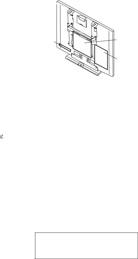
KLV-26T400A,T400G, 32T400A
RM-GA013
6-3. CIRCUIT BOARD LOCATION (KLV-26T400, 32T400)
GPT Board
HT Board
BT Board
6-4. SCHEMATIC DIAGRAM |
6-5. PRINTED WIRING BOARDS |
Board |
Function |
Note |
|
|
|
BT |
I/O, AV INPUT/OUTPUT, HDMI, |
Due to complexity of the board, performing |
|
PC,I, HP/AUDIO/LOC TOP/DDR/ |
component level field repairs are not |
|
POWER DC/ TUNER.FM.IF/ |
recommended. Complete board |
|
AV SWITCH.SMIC |
replacement is required if service is |
GPT |
Power Supply |
necessary. |
|
|
Therefore schematic diagrams and |
HT |
Key / LED / SIRCS |
printed wiring boards are not included. |
|
|
For part number information, refer to |
|
|
Exploded View or Electrical Parts List |
|
|
section in this manual. |
|
|
|
6-6. SEMICONDUCTOR
Due to complexity of the board, performing component level field repairs are not recommended. Complete board replacement is required if service is necessary.
– 25 –
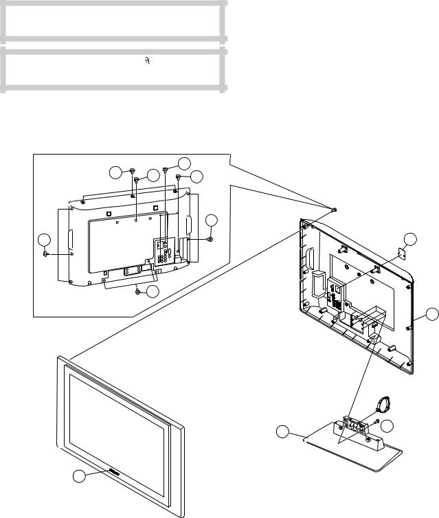
KLV-26T400A,T400G, 32T400A
RM-GA013
SECTION 7
EXPLODED VIEWS
•Components not identified by a part number or description are not stocked because they are not required for routine service.
•The component parts of an assembly are indicated by the reference numbers in the far right column of the part list and within the dotted lines of the diagram.
•Item marked with an asterisk (*) are not stocked since they are seldom required for routine service. Some delay should be anticipated when ordering these components.
NOTE: The components identified by shading and ! mark are critical for safety. Replace only with part number specified.
Note: The components identified by mark contain confidential information. Strictly follow the instructions whenever the components are repaired and /or replaced.
(KLV-26T400)
7-1-1. REAR CABINET
f |
|
a |
b |
m |
f
f
f
4
a |
2-580-591-01 |
SCREW, +PSW M3X5 |
b |
2-580-600-01 |
SCREW, +PSW M4X8 |
c |
2-580-608-01 |
SCREW, +PSW M5X16 |
d |
2-580-626-01 |
SCREW, SP 4-4O UNC |
e |
2-580-629-01 |
SCREW, +BVST 3X8 |
f |
2-580-640-01 |
SCREW, +BVTP2 4X16 |
g |
2-580-644-01 |
SCREW, +KTP2 3X8 |
h |
2-580-649-01 |
SCREW, +PWTP2 3X12 |
i |
2-580-650-01 |
SCREW, +PWHTP2 3X16 |
j |
2-580-654-01 |
SCREW, +PWTP2 4X16 |
k |
2-674-965-31 |
SCREW, +PSW 3SG |
l |
4-046-797-01 |
SCREW (3X12), (+)BVTAP |
m |
7-685-648-79 |
SCREW +BVTP 3X12 TYPE2 IT-3 |
|
|
|
2
1
i
3
REF. NO. |
PART NO. |
DESCRIPTION |
REMARK |
|
1 |
|
X-2190-757-1 |
REAR COVER (TG26) ASSY (26A) |
|
|
|
X-2320-128-1 |
REAR COVER ASSY (26G) |
|
2 |
* |
3-106-086-01 |
COVER, ECS |
|
3X-2190-754-1 STAND (M) ASSY
44-103-599-21 EMBLEM, SONY NO.7
– 26 –

KLV-26T400A,T400G, 32T400A
RM-GA013
7-1-2. POWER CORD, AC CORD HOLDER
52 |
51 |
|
 50
50
REF. NO. PART NO. |
DESCRIPTION |
REMARK |
|
50 |
! 1-835-128-11 |
POWER SUPPLY CORD |
|
|
|
(WITH CONNEC (26A (NZ)) |
|
|
1-835-136-11 |
POWERSUPPLYCORD(WITHCONNECTER) |
|
|
|
(26A (E,GE,ME,SAF), 26G (E, GE, ME)) |
|
|
1-835-280-11 |
POWERSUPPLYCORD(WITHCONNECTOR) |
|
|
|
(26A (ID), 26G (ID)) |
|
51 |
4-022-115-00 |
HOLDER, AC CORD |
|
52 |
1-500-386-11 |
FILTER, CLAMP (26A (NZ)) |
|
– 27 –
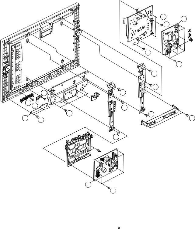
KLV-26T400A,T400G, 32T400A
RM-GA013
7-1-3. BT, HT, GPT BOARD
 f 104 b
|
|
e |
|
|
e |
|
|
f |
|
|
b |
|
m |
f |
m 103 |
|
b |
|
|
|
102 |
f |
b |
m |
b |
|
|
|
|
|
|
b |
101
k
REF. NO. |
PART NO. |
DESCRIPTION |
REMARK |
101 |
A-1553-047-A |
GPT COMPLETE |
|
102 |
A-1550-333-A |
HT MOUNT |
|
103 |
3-452-787-01 |
GUIDE,LIGHT |
|
104 |
A-1558-681-A |
BT MOUNT (SERVICE) |
|
– 28 –

KLV-26T400A,T400G, 32T400A
RM-GA013
7-1-4. SPEAKER, BEZEL ASSY AND LCD PANEL
153
150
151
f
150
f
f
 152
152
REF. NO. |
PART NO. |
DESCRIPTION |
REMARK |
|
150 |
1-858-037-11 |
LOUDSPEAKER (13X5.5CM) |
|
|
|
|
|
|
|
151 ! |
1-802-706-11 |
LCD PANEL (26 INCH WXGA TFT) |
|
|
152 |
* |
1-835-793-11 |
HARNESS WITH CONNECTOR (LVDS) (26A (NZ)) |
|
|
* |
1-835-722-11 |
HARNESS WITH CONNECTOR (LVDS) |
|
|
|
|
(except 26A(NZ)) |
|
153 |
|
X-2190-755-1 |
BEZEL (TG26) ASSY (26A) |
|
|
|
X-2319-390-1 |
FRONT PANEL (TG26) ASSY (26G) |
|
– 29 –
Loading...