


 Loading...
Sony KLV-20S400A, KLV-20S400B, KLV-20S400D, KLV-20S400G, KLV-20S400L Service Manual
...REVISION HISTORY EG1L (GA) CHASSIS
MODEL |
PART NO.: 9-872-998-01 |
KLV-20S400A
KLV-20S400A/B
KLV-20S400A/D
KLV-20S400A/G
KLV-20S400A/L
KLV-20S400A/P
NO. |
SUFFIX |
DATE |
SUPP / CORR |
DESCRIPTION |
|
|
|
|
|
1 |
-01 |
2008/6 |
_ _ |
1st Issue |
|
|
|
|
|
|
|
|
|
|
|
|
|
|
|
|
|
|
|
|
|
|
|
|
|
|
|
|
|
|
|
|
|
|
|
|
|
|
|
|
|
|
|
|
|
|
|
|
|
|
|
|
|
|
|
|
|
|
|
|
|
|
|
|
|
|
|
|
|
|
|
|
|
|
|
|
|
|
|
|
|
SERVICE MANUAL |
|
|
|
|
EG1L (GA)CHASSIS |
||||||||||||||||||||||||||||||||||
|
MODEL |
COMMANDER DEST. |
MODEL |
|
COMMANDER DEST. |
|||||||||||||||||||||||||||||||||||
|
|
|
|
|
|
|
|
|
|
|
|
|
|
|
|
|
|
|
|
|
|
|
|
|
|
|
|
|
|
|
|
|
|
|
|
|
|
|
|
|
KLV-20S400A RM-GA011/W EA, ME, Vietnam
KLV-20S400A/B RM-GA011/W EA, E, New Zealand
India, ME, Thailand
KLV-20S400A/D RM-GA011/W EA, ME, Thailand
KLV-20S400A/G RM-GA011/W EA, ME, Thailand
KLV-20S400A/L RM-GA011/W EA, ME, Thailand
KLV-20S400A/P RM-GA011/W EA, ME, Thailand
RM-GA011/W
LCD COLOR TV
KLV-20S400A
RM-GA011/W
TABLE OF CONTENTS
Section Title |
Page |
|
Section Title |
Page |
||||||||
|
|
|
|
|
|
|
|
|
|
|
|
|
1. |
SAFETY NOTES |
|
|
|
5. |
SERVICE ADJUSTMENTS |
|
|
||||
|
1-1. Caution Handling of LCD Panel ..................................... |
|
3 |
|
|
5-1. Accessing Diagnostic Menu .......................................... |
12 |
|||||
|
1-2. Safety Check Out ............................................................. |
|
3 |
|
|
5-2. Aging ............................................................................ |
12 |
|||||
|
1-3. Leakage Test .................................................................... |
|
3 |
|
|
5-3. Resetting the User MenuFactory Reset ...................... |
12 |
|||||
|
1-4. WARNING ! .................................................................... |
|
3 |
|
|
5-4. White Balance Adjustment ............................................ |
13 |
|||||
|
1-5. Lead Free Information ..................................................... |
|
4 |
|
|
5-5. Board & Panel Replacement ......................................... |
13 |
|||||
2. |
SELF DIAGNOSTIC FUNCTION |
|
|
|
6. |
DIAGRAMS |
|
|
||||
|
2-1. Overview of Control Buttons .......................................... |
|
5 |
|
|
6-1. Block Diagram ............................................................... |
14 |
|||||
|
2-2. LED Display Specification .............................................. |
|
5 |
|
|
6-2. Circuit Board Location .................................................. |
14 |
|||||
|
2-3. LED Display Control ....................................................... |
|
5 |
|
|
6-3. Schematic Diagram ....................................................... |
15 |
|||||
|
2-4. LED Pattern ..................................................................... |
|
5 |
|
|
6-4. Printed Wiring Boards ................................................... |
15 |
|||||
|
2-5. Standby LED Error Display ............................................ |
|
6 |
|
|
6-5. Semiconductor ............................................................... |
15 |
|||||
3. |
DISASSEMBLY |
|
|
|
7. |
EXPLODED VIEWS |
|
|
||||
|
3-1. Rear Cover and Stand Assy Removal ............................. |
|
7 |
|
|
7-1. Rear Cabinet .................................................................. |
16 |
|||||
|
3-2. H1S Board Removal ........................................................ |
|
7 |
|
|
7-2. Power Cord, AC Cord Holder, Chassis, H1S Boards ... 17 |
||||||
|
3-3. GD Board and Bracket Removal ..................................... |
|
7 |
|
|
7-3. GD, BG1, Inverter Boards, Bezel Assy and |
|
|
||||
|
3-4. Inverter Board Removal .................................................. |
|
7 |
|
|
LCD Panel ..................................................................... |
18 |
|||||
|
3-5. Side Jack Bracket Assy and BG1 Board Removal ......... |
|
7 |
|
|
7-4. Speaker, H3S Board ...................................................... |
19 |
|||||
|
3-6. Vesa Frame Removal ....................................................... |
|
7 |
|
|
|
|
|
|
|||
|
3-7. H3S Board, Speaker Bracket and |
|
|
|
|
|
|
|
|
|
||
|
Loudspeaker Removal ..................................................... |
|
8 |
8. |
ELECTRICAL PARTS LIST .............................................. |
20 |
||||||
|
3-8. LCD Panel and Bezel Assy Removal .............................. |
|
8 |
|
|
|
|
|
|
|||
|
|
|
|
|
|
|
|
|
OPERATING INSTRUCTIONS |
|
|
|
4. |
WIRE DRESSING |
|
|
|
|
|
|
|
|
|
||
|
4-1. Wire Dressing Overview (for Non-CISPR model) ......... |
|
9 |
|
|
|
|
|
|
|||
|
4-2. Wire Dressing Overview (for CISPR model) ................. |
|
9 |
|
|
|
|
|
|
|||
|
4-3. Dress LVDS cable with Sheet Core C |
|
|
|
|
|
|
|
|
|
||
|
(for Non-CISPR model) .................................................. |
|
9 |
|
|
|
|
|
|
|||
|
4-4. Dress LVDS cable with Sheet Core C & Shield Tape |
|
|
|
|
|
|
|
|
|||
|
(for CISPR model) .......................................................... |
|
9 |
|
|
|
|
|
|
|||
|
4-5. Insert wire from panel to inverter board and make sure |
|
|
|
|
|
|
|
|
|||
|
wire color is matching with color on connector ............. |
|
9 |
|
|
|
|
|
|
|||
|
4-6. Dress Connector Assy 14P+20P with Sheet Core C |
. ..... |
9 |
|
|
|
|
|
|
|||
|
4-7. Dress Connector Assy 14P+20P with LCD tape(3X) ... |
10 |
|
|
|
|
|
|
||||
|
4-8. 1) Dress Connector Assy 14P+20P at GD |
|
|
|
|
|
|
|
|
|
||
|
bracket hook(6X) |
|
|
|
|
|
|
|
|
|
||
|
2) Dress Speaker wire at GD bracker's hook(4X) |
|
|
|
|
|
|
|
|
|
||
|
3) Dress speaker wire with LCD tape ........................... |
|
10 |
|
|
|
|
|
|
|||
|
4-9. Dress LVDS cable with Sheet Core C |
|
|
|
|
|
|
|
|
|
||
|
(for Non-CISPR model) ................................................ |
|
10 |
|
|
|
|
|
|
|||
|
4-10.Screw LVDS cable's clamp on main bracket |
|
|
|
|
|
|
|
|
|
||
|
(for CISPR model) ......................................................... |
|
10 |
|
|
|
|
|
|
|||
|
4-11.1) Screw Connector Assy 1P on BG1 & bottom Bracket |
|
|
|
|
|
|
|||||
|
2) Put Connector Assy 1P underneath Speaker wire .... |
11 |
|
|
|
|
|
|
||||
|
4-12.Install AC cord holder on AC power cord and dress |
|
|
|
|
|
|
|
|
|||
|
at GD bracket's hook ..................................................... |
|
11 |
|
|
|
|
|
|
|||
– 2 –

KLV-20S400A
RM-GA011/W
SECTION 1
SAFETY NOTES
1-1. Caution Handling of LCD Panel
When installing the LCD Panel, make sure you are grounded with a wrist band.
When installing the LCD Panel on the wall, the panel must be secured using the 4 mounting holes on the rear cover.
1)Do not press the panel or frame edge to avoid the risk of electric shock.
2)Do not scratch or press on the panel with any sharp objects.
3)Do not leave the module in high temperature or in areas of high humidity for an extended period of time.
4)Do not expose the LCD panel to direct sunlight.
5)Avoid contact with water. It may cause short circuit within the module.
6)Disconnect the AC adapter when replacing the backlight (CCFL) or inverter circuit. (High voltage occurs at the inverter circuit at 650Vrms)
7)Always clean the LCD panel with a soft cloth material.
8)Use care when handling the wires or connectors of the inverter circuit. Damaging the wires may cause a short circuit.
9)Protect the panel from ESD to avoid damaging the electronic circuit (C-MOS).
1-2. Safety Check-Out
After correcting the original service problem, perform the following safety checks before releasing the set to the customer:-
1)Check the area of your repair for unsoldered or poorly soldered connections. Check the entire board surface for solder splashes and bridges.
2)Check the interboard wiring to ensure that no wires are "pinched" or contact high-wattage resistors.
3)Check all control knobs, shields, covers, ground straps and mounting hardware have been replaced. Be absolutely certain you have replaced all the insulators.
4)Look for unauthorized replacement parts, particularly transistors that were installed during a previous repair. Point them out to the customer and recommend their replacement.
5)Look for parts which, though functioning show obvious signs of deterioration. Point them out to the customer and recommend their replacement.
6)Check the line cords for cracks and abrasion. Recommend the replacement of any such line cord to the customer.
7)Check the antenna terminals, metal trim, "metallized" knobs, screws and all other exposed metal parts for AC leakage. Check leakage test as described next.
1-3. Leakage Test
The AC leakage from any exposed metal part to earth ground and from all exposed metal parts to any exposed metal part having a return to chassis must not exceed 0.5mA (500 microamperes). Leakage current can be measured by any one of the three methods:-
1.A commercial leakage tester such as the SIMPSON 229 or RCA WT-540A. Follow the manufacturers instructions to use those instructions.
2.A battery-operated AC milliampmeter. The DATA PRECISION 245 digital multimeter is suitable for this job.
3.Measuring the voltage drop across a resistor by means of a VOM or battery operated AC voltmeter. The 'limit' indication is 0.75V so analog meters must have an accurate low voltage scale. The SIMPSON'S 250 and SANWA SH-63TRD are examples of passive VOMs that are suitable. Nearly all battery operated digital multimeters that have a 2 VAC range are suitable. (see Figure 1.)
To Exposed Metal
Parts on Set
AC
0.15 F 1.5 kΩ Voltmeter
(0.75 V)
Earth Ground
Figure 1. AC voltmeter to check AC leakage
1-4. WARNING !
SAFETY-RELATED COMPONENT WARNING! COMPONENTS IDENTIFIED BY SHADING AND MARK ! ON THE EXPLODED VIEWS ARE CRITICAL FOR SAFE OPERATION. REPLACE THESE COMPONENTS WITH SONY PARTS WHOSE PART NUMBERS APPEAR AS SHOWN IN THIS MANUAL OR IN SUPPLEMENTS PUBLISHED BY SONY. CIRCUIT ADJUSTMENTS THAT ARE CRITICAL FOR SAFE OPERATION ARE IDENTIFIED IN THIS MANUAL. FOLLOW THESE PROCEDURES WHENEVER CRITICAL COMPONENTS ARE REPLACED OR IMPROPER OPERATION IS SUSPECTED.
– 3 –
KLV-20S400A
RM-GA011/W
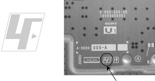
1-5. Lead Free Information
The circuit boards used in these models have been processed using Lead Free Solder. The boards are identified by the LF logo located close to the board designation.
Figure 2: LF logo
Figure 3: LF logo on circuit board
The servicing of these boards requires special precautions. It is strongly recommended to use Lead Free Solder material in order to guarantee optimal quality of new solder joints. Lead Free Solder is available under the following part numbers:-
Part number |
Diameter |
Remarks |
7-640-005-19 |
0.3mm |
0.25Kg |
|
|
|
7-640-005-20 |
0.4mm |
0.50Kg |
7-640-005-21 |
0.5mm |
0.50Kg |
|
|
|
7-640-005-22 |
0.6mm |
0.25Kg |
|
|
|
7-640-005-23 |
0.8mm |
1.00Kg |
|
|
|
7-640-005-24 |
1.0mm |
1.00Kg |
7-640-005-25 |
1.2mm |
1.00Kg |
|
|
|
7-640-005-26 |
1.6mm |
1.00Kg |
|
|
|
Due to high melting point of Lead Free Solder, the soldering iron tip temperature needs to be set to 370 degrees centigrade. This requires soldering equipment capable of accurate temperature control coupled with a good heat recovery characteristics.
For more information on the use of Lead Free Solder, please refer to http://www.sony-training.com
– 4 –

KLV-20S400A
RM-GA011/W
SECTION 2
SELF DIAGNOSTIC FUNCTION
2-1. Overview of Control Buttons
MENU TV/VIDEO |
VOLUME |
CHANNEL POWER |
|
PICTURE OFF/ |
STANDBY |
POWER |
REMOTE/LIGHT SENSOR |
TIMER |
|
|
|
2-4. LED Pattern
When safety shutdown occurs, Standby LED display reports the cause by using the blinking patterns as indicated below.
2.0 sec |
2.0 sec |
0.3 sec |
|
0.3 sec |
|
Example:
The figure above shows LED display when SHUTDOWN is caused by DC_ALERT 2. It repeats flashing for a specified number of times in 0.3sec/ cycle and has a 2 seconds interval of lighting off. Please note that a 2 seconds interval of lighting off is fixed regardless of abnormal state types.
2-2. LED Display Specification
LED Type |
Description |
|
Remark |
|
|
||
POWER |
Green: One LED |
Green lights at power ON. |
|
|
|||
|
|
|
|
|
|||
STANDBY |
Red: One LED |
Red lights during standby. |
|
|
|||
|
|
|
|
|
|||
|
Green/Amber |
Green lights during Picture |
|
|
|||
Timer |
: Two LEDs |
OFF and amber lights |
|
|
|||
|
|
during Timer activation. |
|
|
|||
|
|
|
|
|
|
||
2-3. LED Display Control |
|
|
|
|
|
||
|
|
|
|
|
|
||
Status |
Display |
|
Remark |
||||
Power LED Standby LED |
|||||||
|
|
|
|
||||
POWER ON |
Green lights |
OFF |
|
Microcomputer is |
|||
|
in a normal state. |
||||||
|
|
|
|
||||
|
|
|
|
||||
STANDBY |
OFF |
Red lights Microcomputer is |
|||||
|
|
|
|
in a sleep state. |
|||
Classify the Failure 


 trouble causes by
the no. of red blinking.
– 5 –
KLV-20S400A
RM-GA011/W
2-5. Standby LED Error Display
Perform below countermeasures according to Standby LED blinking times.
Blinking times |
Error |
Countermeasure |
|
|
|
2 |
DC_DET (12V Main Voltage) |
Replace either/both z BG1 board |
|
|
z GP(26",32")/ |
|
|
Power Unit(G2D)(37") board |
|
|
Power Unit GD(20”) board |
|
|
|
3 |
DC_ALERT 1 |
Replace BG1 board. |
|
|
|
4 |
DC_ALERT 2 |
Replace BG1 board. |
|
|
|
5 |
DC_ALERT 3 |
Replace BG1 board. |
|
|
|
6 |
BACKLIGHT/ |
Replace BG1 board. |
|
INVERTER ERROR |
|
|
|
|
7 |
INTERNAL TEMP |
Replace GP(26",32")/Power Unit(G2D)(37") board |
|
ERROR |
Power Unit GD(20”) board |
|
|
BG1 board |
|
|
|
8 |
AUDIO ERROR |
Replace either/both z BG1 board |
|
|
z GP(26",32")/ |
|
|
Power Unit(G2D)(37") board |
|
|
z Speaker |
|
|
|
9 |
Not used for GA |
— |
|
|
|
10 |
Not used for GA |
— |
|
|
|
11 |
NVM ERROR |
Replace either/both z BG1 board |
|
|
|
12 |
IIC ERROR |
Replace BG1 board. |
|
|
|
13 |
BALANCER ERROR |
Replace BG1 board. |
|
|
|
14 |
HDMI ERROR |
— |
|
|
|
Note: Each of the above blinking repeats every 2 seconds.
– 6 –

KLV-20S400A
RM-GA011/W
|
SECTION 3 |
|
|
|
DISASSEMBLY |
|
|
3-1. Rear Cover and Stand Assy Removal |
3-2. H1S Board Removal |
||
9 Four screws |
|
|
4 Two screws |
7 Two screws |
|
(BVTP2 4 X 16) |
|
(+PSW M4 X 12) |
|
||
(+PSW M4 X 12) |
|
|
|
|
|
|
|
0 Handle Assy |
8 Stand (20AG) Assy |
3 Button (B) |
4 H1S board |
|
|
||
|
|
Bracket |
|
4 Two screws |
5 Two screws |
|
2 Lift tabs to |
(BVTP2 3 X 12) |
|
||
|
remove board |
||
(+BVTP 3 X 12) |
|
|
|
6 AC Cover |
|
|
|
3 Two screws |
|
|
|
|
|
|
|
(+PSW M3 X 5) |
2 Four screws |
|
|
|
|
|
|
1 Eight screws |
(BVTP2 3 X 12) |
|
|
|
|
|
|
(BVTP2 4 X 20) |
|
|
|
qa Lift to remove Rear Cover
3-3. GD Board and Bracket Removal |
3-4. Inverter Board Removal |
|
1 Four screws |
1 Six screws |
|
(+PSW 3SG) |
(+BVST 3 X 8) |
2Inverter |
|
||
2 One connector |
|
|
|
Shield |
|
3 One connector |
|
5Three |
4 GD Compl |
3Three screws |
Connectors |
|
||
Kit (STT) |
(+BVST 3 X 8) |
7Inverter |
|
|
|
|
|
board |
|
6Three |
4One |
5 GD (20) Bracket |
Connectors |
connector |
|
|
3-5. Side Jack Bracket Assy and BG1 |
3-6. Vesa Frame Removal |
|
|
Board Removal |
|
|
|
1 One screw |
|
3 Four screws |
1 One screw |
2 Side Jack (20) |
(+PSW M4 X 8) |
||
(+PSW M3 X 5) |
Bracket Assy |
(+PSW M4 X 8) |
|
|
3 Nine screws |
|
2 Frame |
|
(+BVST 3 X 8) |
|
|
|
|
|
|
|
|
|
4 Two screws |
6 BG1 board |
|
|
(BVTP2 4 X 16) |
4 Two Connectors |
|
|
|
|
|
|
|
5 Two Connectors |
|
|
|
|
|
|
5 LCD Bracket |
|
|
|
(20-EG1L) Assy |
|
|
– 7 – |
|

KLV-20S400A
RM-GA011/W
3-7. H3S Board, Speaker Bracket and |
3-8. LCD Panel and Bezel Assy Removal |
Loudspeaker Removal |
|
1 Two screws |
2 Harness |
(BVTP2 4 X 16) |
with connector |
2 Speaker Bracket |
|
3 Four screws |
3 LCD panel |
(+BVTP 3 X 12) |
|
|
6 Two screws |
4 Loudspeaker |
(BVTP2 4 X 16) |
|
|
5 Four screws |
|
(+BVTP 3 X 12) |
1 |
|
7 H3S board |
4 Bezel (20) assy
– 8 –

KLV-20S400A
SECTION 4
WIRE DRESSING
RM-GA011/W
CAUTION :
1.Do not overpull the wires during dressing --> avoid disconnection of wires.
2.Make sure wires are kept away from sharp edges, heatsinks & other high-temperature parts.
4-1. Wire Dressing Overview
(for Non-CISPR model).
4-2. Wire Dressing Overview
(for CISPR model).
4-3. Dress LVDS cable with Sheet Core C (for Non-CISPR model).
Make sure LVDS connector fully |
|
NG |
|
|
|
|||||
inserted |
|
|
|
|
|
|||||
|
|
|
|
|||||||
with correct direction as shown. |
|
|
|
|
|
|||||
|
|
|
|
|
|
|
|
|
|
|
|
|
|
|
|
|
|
|
|
|
|
|
|
|
OK |
|
|
|
|
|
|
|
|
|
|
|
|
|
|
|
|
|
|
|
|
|
|
|
|
|
|
|
|
|
|
|
LVDS cable |
|
|
|
|
|
|
|
|
|
|
|
|
|
|
|
|
|
||
|
|
|
|
|
|
|||||
|
Use edge of UL tape |
|
|
|
|
Datum |
||||
|
as guide line |
|
|
|
|
|
||||
|
|
|
|
|
|
|
|
|
|
|
|
|
|
|
|
|
|
|
|
|
|
|
|
|
|
|
|
|
|
|
Sheet Core C |
|
|
|
|
|
|
|
|
|
|
|
|
|
|
|
|
|
|
|
|
|
|
|
4-4. Dress LVDS cable with Sheet Core C & Shield Tape (For CISPR model).
Make sure LVDS connector fully inserted |
NG |
with correct direction as shown. |
|
|
OK |
Datum |
LVDS cable |
Shield Tape |
Sheet Core C |
4-5. Insert wire from panel to inverter board and make sure wire color is matching with color on connector.
Wire from panel |
|
Wire from panel |
|
|
|
4-6. Dress Connector Assy 14P+20P with Sheet Core C.
Connector assy 14P+20P
Datum
 Sheet Core C
Use edge of UL tape as guide line
– 9 –
KLV-20S400A
RM-GA011/W
4-7. Dress Connector Assy 14P+20P with LCD tape(3X).
|
Connector assy 14P+20P |
LCD Tape |
LCD Tape |
Use edge of UL tape as guide line
Use edge of UL tape as guide line
4-8. 1) Dress Connector Assy 14P+20P at GD bracket's hook(6X).
2)Dress Speaker wire at GD bracket's hook(4X).
3)Dress speaker wire with LCD tape.
Connector assy 14P+20P
LCD Tape
Speaker Wire
Speaker Wire |
Datum |
Caution :
avoid screw boss on rear cover
4-9. Dress LVDS cable with Sheet Core C |
4-10. Screw LVDS cable's clamp on main bracket |
(for Non-CISPR model). |
(for CISPR model). |
|
LVDS Cable |
Sheet Core C LVDS Cable |
LVDS cable's clamp |
|
Screw |
Datum |
Datum |
– 10 –

KLV-20S400A
RM-GA011/W
4-11. 1) Screw Connector Assy 1P on BG1 & Bottom Bracket. 2) Put Connector Assy 1P underneath Speaker wire.
Speaker Wire
Connector Assy 1P
~90
~45
4-12. Install AC cord holder on AC power cord and dress at GD bracket's hook.
|
|
AAC Cord holder |
|
AAC Power Cord |
|
|
|||||||||||||||||||||||||||
|
|
|
|
|
|
|
|
|
|
|
|
|
|
|
|
|
|
|
|
|
|
|
|
|
|
|
|
|
|
|
|
|
|
|
|
|
|
|
|
|
|
|
|
|
|
|
|
|
|
|
|
|
|
|
|
|
|
|
|
|
|
|
|
|
|
|
|
|
|
|
|
|
|
|
|
|
|
|
|
|
|
|
|
|
|
|
|
|
|
|
|
|
|
|
|
|
|
|
|
|
|
|
|
|
|
|
|
|
|
|
|
|
|
|
|
|
|
|
|
|
|
|
|
|
|
|
|
|
|
|
|
|
|
|
|
190mm
AC Power Cord
– 11 –

KLV-20S400A
RM-GA011/W
SECTION 5
SERVICE ADJUSTMENTS
5-1. Accessing Diagnostic Menu
1.While TV set on standby, press the following sequence on the remote commander (RM-GA011/W).
On screen |
Channel 5 |
|
|
|
POWER |
Volume (-) |
|||||
display |
|
|
|
|
|
|
|
|
|
|
|
3. Press V/v to select ‘Service’.
Service Menu
Status
W/B
Service
Figure 4
4. Press B/b or  to view ‘Service’ category items.
2.The following menu will appear on the screen:
ERROR
DC_DET |
0 |
DC_ALERT1 |
0 |
DC_ALERT2 |
0 |
DC_ALERT3 |
0 |
BACKLIGHT |
0 |
INTERNAL TEMP ERROR |
0 |
AUDIO ERROR |
0 |
NVM ERROR |
0 |
IIC ERROR |
0 |
BALANCER ERROR |
0 |
HDMI ERROR |
0 |
RESET |
0 |
Figure 1
3.To reset, select ‘RESET’ using remote commander and
press  to execute RESET.
4.To quit the diagnostic menu, turn off and on the TV set.
5-2. Aging
1.While TV set on standby, press the following sequence on the remote commander (RM-GA011/W).
On screen |
|
|
|
|
|
|
Channel 5 |
Volume (+) |
POWER |
||||
display |
||||||
|
|
|
|
|
||
Figure 2
2.The following menu will appear on the screen.
Service Menu
Status
W/B
Service
Figure 3
Press V/v to select ‘PATTERN’. Then press B/b then V/v
to select ‘WHITE PATTERN’ and  .
.
Service Menu
Service
|
|
TEST RESET |
Cancel |
|
|
|
PATTERN |
WHITE PATTERN |
|
|
|
|
|
|
|
|
PRODUCTION |
11111111 |
|
|
|
|
|
|
|
|
APC |
Normal |
|
|
|
|
|
|
|
|
OVER MODULATION |
Off |
|
|
|
|
|
|
|
|
OPTIONS |
OPT 1 |
|
|
|
|
|
|
|
|
AUTOSET FACTORY |
|
DEFAULT |
|
|
|
|
|
|
|
SERIAL NUMBER EDIT |
|
|
|
|
|
|
|
|
|
ETI1 CLEAR |
|
Cancel |
|
|
|
|
|
|
|
No Signal Mute |
|
Off |
|
|
|
|
|
Figure 5
5.The aging Condition is as the following:
a) Supply voltage |
: Rating |
b) Time |
: 20 minutes or over |
c) Ambient Temp |
: 22~28 degrees |
5-3. Resetting the User Menu - Factory Reset
Note: THE TEST RESET option resets all the customer adjustable data back to factory defaults.
1.While TV set on standby, press the following sequence on the remote commander (RM-GA011/W).
On screen |
Channel 5 |
|
|
|
POWER |
Volume (-) |
|||||
display |
|
|
|
|
|
|
|
|
|
|
|
Figure 6
2.The following menu will appear on the screen:
Service Menu
Status
W/B
Service
Figure 7
– 12 –

3. Press V/v to select ‘Service’.
Service Menu
Status
W/B
Service
Figure 8
4.Then press B/b or  to view ‘Service’ category items. Next select ‘TEST RESET’ by pressing V/v .
5.Finally press B/b or  then V/v to select ‘OK’ and confirm selection by pressing
  .
.
Service Menu
|
Service |
|
|
|
|
TEST RESET |
|
Cancel |
|
|
PATTERN |
|
Off |
|
|
PRODUCTION |
|
11111111 |
|
|
APC |
|
Normal |
|
|
OVER MODULATION |
|
Off |
|
|
OPTIONS |
|
OPT1 |
|
|
AUTOSET FACTORY |
|
DEFAULT |
|
|
SERIAL NUMBER EDIT |
|
|
|
|
ETI1 CLEAR |
|
Cancel |
|
|
No Signal Mute |
|
Off |
|
|
|
|
|
|
Figure 9
5-4. White Balance Adjustment
Note: The white balance need to be adjusted when BG1 board and Panel is replaced.
1.While TV set on standby, press the following sequence on the remote commander (RM-GA011/W).
On screen |
Channel 5 |
|
|
|
POWER |
Volume (-) |
|||||
display |
|
|
|
|
|
|
|
|
|
|
|
Figure 10
2.The following menu will appear on the screen:
Service Menu
Status
W/B
Service
Figure 11
KLV-20S400A
RM-GA011/W
3.Press B/b or  to view ‘W/B’.
Service Menu
Status
W/B
Service
Figure 12
4.Then press B/b or  to view ‘W/B’ category items.
Service Menu
|
|
W/B |
|
|
|
|
|
INITIALIZE |
|
INIT START |
|
|
|
LEVEL |
|
0 |
|
|
|
R_DRIVE |
|
0 |
|
|
|
G_DRIVE |
|
0 |
|
|
|
B_DRIVE |
|
0 |
|
|
|
COLOR_SAVE |
|
Cancel |
|
|
|
|
|
|
|
Figure 13
5.Press V/v to select ‘INITIALIZE’. Then press B/b or  then V/v to select ‘INIT START’ and execute selection by pressing
  .
.
6.W/B need to be adjusted for all LEVEL (0~4).
For Level 0
7.Select 'LEVEL' using V/v and choose ‘0’.Then do adjustment for R_Drive, G_Drive and B_Drive.To increase/ decrease data value, press V/v .
8.Once adjustment has completed for R_Drive, G_Drive and B_Drive, press V/v to select ‘COLOR SAVE’. Next press
B/b then V/v to choose ‘OK’ and press  .
.
9.Repeat step 7 and 8 for level 1~4.
10.Once W/B adjustment has been completed for all levels (0~4), select ‘INITIALIZE’, choose ‘INT END’ and press  .
.
5-5. Board & Panel Replacement
When replacing the BG1 board and Panel, make sure to readjust the W/B.
– 13 –

KLV-20S400A
RM-GA011/W
SECTION 6
DIAGRAMS
6-1. BLOCK DIAGRAM
Due to complexity of the board, performing component level field repairs are not recommended. Complete board replacement is required if service is necessary.
6-2. CIRCUIT BOARD LOCATION
GD Board
H1S Board
Inverter Board
H3S Board
BG1 Board
– 14 –

KLV-20S400A
RM-GA011/W
6-3. SCHEMATIC DIAGRAM |
6-4. PRINTED WIRING BOARDS |
Board |
Function |
Note |
|
|
|
BG1 |
I/O/Audio/VCTP/DDR/HDMI/ |
Due to complexity of the board, performing |
|
DC-DC Converter/Tuner/Sub |
component level field repairs are not |
|
Croma/STBY Micro |
recommended. Complete board |
|
|
replacement is required if service is |
GD |
Power Supply |
necessary. |
|
|
Therefore schematic diagrams and |
H1S |
Key |
printed wiring boards are not included. |
|
|
For part number information, refer to |
|
|
Exploded View or Electrical Parts List |
H3S |
LED/SIRCS/Optical Sensor |
section in this manual. |
INVERTER |
INVERTER BOARD |
|
BOARD |
|
|
|
|
|
6-5. SEMICONDUCTOR
Due to complexity of the board, performing component level field repairs are not recommended. Complete board replacement is required if service is necessary.
– 15 –

KLV-20S400A
RM-GA011/W
SECTION 7
EXPLODED VIEWS
•Components not identified by a part number or description are not stocked because they are not required for routine service.
•The component parts of an assembly are indicated by the reference numbers in the far right column of the part list and within the dotted lines of the diagram.
•Item marked with an asterisk (*) are not stocked since they are seldom required for routine service. Some delay should be anticipated when ordering these components.
NOTE: The components identified by shading and ! mark are critical for safety. Replace only with part number specified.
Note: The components identified by mark contain confidential information. Strictly follow the instructions whenever the components are repaired and /or replaced.
7-1 REAR CABINET
a |
2-580-591-01 |
SCREW, +PSW M3X5 (KLV-20S400A(ME)), |
|
|
(KLV-20S400A/B/D/G/L/P(ME,Thailand)) |
b |
2-580-591-01 |
SCREW, +PSW M3X5 |
c |
2-580-592-01 |
SCREW, +PSW M3X8 |
|
|
(KLV-20S400A(Vietnam)) |
d |
2-580-600-01 |
SCREW, +PSW M4X8 |
e |
2-580-602-01 |
SCREW, +PSW M4X12 |
f |
2-580-614-01 |
SCREW, +K M3X8 |
g |
2-580-626-01 |
SCREW, SP 4-40 UNC |
h |
2-580-629-01 |
SCREW, +BVST 3X8 |
i |
2-580-640-01 |
SCREW, +BVTP2 4X16 |
j |
2-580-644-01 |
SCREW, +KTP2 3X8 |
k |
2-580-645-01 |
SCREW, +KTP2 3X10 |
l |
2-674-965-31 |
SCREW, +PSW 3SG |
m |
3-398-903-01 |
SCREW, BVTP2 4X20 (S) |
n |
7-685-648-79 |
SCREW, +BVTP 3X12 TYPE2 IT-3 |
|
|
|
m
n
10
REF. NO. PART NO. |
DESCRIPTION |
REMARK |
|
|
|
|
|
1 |
! X-2318-970-1 |
REAR COVER (20) ASSY |
|
|
|
|
|
|
|
(KLV-20(Vietnam), KLV-20A/B/D/G/L/P(Thailand)) |
|
|
X-2318-970-1 |
REAR COVER (20) ASSY (except KLV-20(Vietnam), |
|
|
|
KLV-20A/B/D/G/L/P(Thailand)) |
|
2 |
3-094-483-21 |
COVER, ECS |
|
3X-2319-195-1 STAND(20AG) ASSY
43-293-799-01 CUSHION (FOOT)
53-293-799-11 CUSHION (FOOT)
6
7 |
e |
2
8
n
1
5
4
e
|
|
|
9 |
|
|
3 |
|
REF. NO. |
PART NO. |
DESCRIPTION |
REMARK |
6 |
X-2190-287-1 |
HANDLE ASSY |
|
7 |
3-288-680-01 |
HANDLE (AB) |
|
8 |
3-288-697-02 |
COVER, AC |
|
9 |
2-595-155-11 |
CLAMP (KLV-20/B (E, EA, India, New Zealand, |
|
|
|
Thailand), KLV-20/D (EA, Thailand), 20/G/L/P (EA)) |
|
10 |
3-285-056-01 |
BUTTON, MULTI (B) |
|
– 16 –

KLV-20S400A
RM-GA011/W
7-2. POWER CORD, AC CORD HOLDER, CHASSIS, H1S BOARDS
52
 i
i
53 54
51
 50
50
REF. NO. PART NO. |
DESCRIPTION |
REMARK |
|
|
|
50 ! 1-835-128-11 |
POWER SUPPLY CORD (WITH CONNEC) |
|
|
|
|
|
(KLV-20/B (New Zealand)) |
|
|
|
|
! 1-835-136-11 |
POWERSUPPLYCOR (WITHCONNECTER) |
|
|
|
|
|
(KLV-20(EA, ME, Vietnam), KLV-20/B (E, EA, ME), |
|
|
|
|
|
KLV-20/D/G/LP(EA, ME)) |
|
|
|
|
! 1-835-127-11 |
POWERSUPPLYCORD(WITHCONNECTER) |
|
|
|
|
|
(KLV-20/B/D/G/L/P (Thailand)) |
|
|
|
|
! 1-835-280-11 POWERSUPPLYCORD(WITHCONNECTOR) (KLV-20/B (India))
REF. NO. PART NO. |
DESCRIPTION |
REMARK |
514-022-115-12 HOLDER, AC CORD
523-284-998-02 BRACKET, BUTTON (B)
53* A-1545-906-A H1S MOUNT
54A-1558-284-A MULTI BUTTON ASSY (KLV-20 (Vietnam)) A-1552-888-A MULTI BUTTON ASSY (KLV-20/B (New Zealand)) A-1552-732-A MULTI BUTTON ASSY
(except 20/20/B (New Zealand))
– 17 –
KLV-20S400A
RM-GA011/W
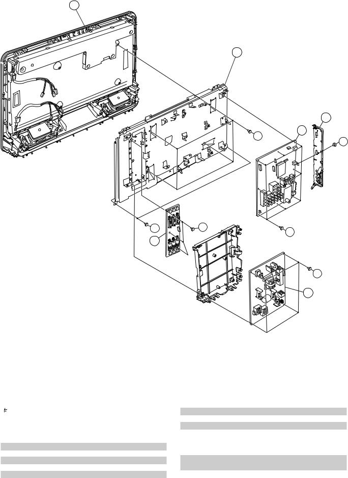
7-3. GD, BG1, INVERTER BOARDS, BEZEL ASSY AND LCD PANEL
104
103
106
102
d
c
i |
h |
|
h |
105 |
|
l
101
REF. NO. |
PART NO. |
DESCRIPTION |
REMARK |
|
101 |
|
A-1507-971-B |
GD COMPL(STT) |
|
102 |
* |
A-1559-845-A |
BG1 MOUNT (COM) |
|
103 |
! |
1-802-566-11 |
LCD PANEL (20 INCH WXGA TFT) |
|
|
|
|
|
|
|
! |
1-802-566-21 |
LCD PANEL (20 INCH WXGA TFT) |
|
|
|
|
||
104 |
! X-2319-312-1 |
BEZEL (20)(D) ASSY (KLV-20/D(Thailand)) |
||
|
|
X-2319-312-1 |
BEZEL (20)(D) ASSY (KLV-20/D(EA, ME)) |
|
!X-2319-311-1 BEZEL (20)(G) ASSY (KLV-20/G(Thailand)) X-2319-311-1 BEZEL (20)(G) ASSY (KLV-20/G(EA, ME,))
!X-2319-328-1 BEZEL(20)(L) ASSY (KLV-20/L(Thailand)) X-2319-328-1 BEZEL(20)(L) ASSY (KLV-20/L(EA, ME))
!X-2319-329-1 BEZEL (20)(P) ASSY (KLV-20/P(Thailand))
REF. NO. PART NO. |
DESCRIPTION |
REMARK |
X-2319-329-1 BEZEL (20)(P) ASSY (KLV-20/P(EA, ME))
!X-2318-969-1 BEZEL (20)(S) ASSY (KLV-20(Vietnam)) X-2318-969-1 BEZEL (20)(S) ASSY (KLV-20(EA, ME))
!X-2319-077-1 BEZEL (20)(B) ASSY (KLV-20(Thailand))
X-2319-077-1 BEZEL (20)(B) ASSY
(KLV-20(E, EA, India, ME, New Zealand)) 105 * 1-789-902-11 MOUNTED BOARD (INVERTER BOARD)
(except KLV-20/B/D/G/L/P(Thailand))
*! 1-789-902-11 MOUNTED BOARD (INVERTER BOARD)
|
(KLV-20/B/D/G/L/P(Thailand)) |
106 |
3-284-296-11 COVER, MS |
– 18 –

KLV-20S400A
RM-GA011/W
7-4. SPEAKER, H3S BOARD
n
n
151
150 |
i |
i
REF. NO. PART NO. |
DESCRIPTION |
REMARK |
|
150 |
* A-1545-905-A |
H3S MOUNT |
|
151 |
1-826-871-11 |
LOUDSPEAKER (4X10CM) |
|
– 19 –
KLV-20S400A
RM-GA011/W
SECTION 8
ELECTRICAL PARTS LIST
NOTE: |
DESCRIPTION |
REF NO. PART NO. |
The components identified by mark  contain confidential information. Strictly follow the instructions whenever the components are repaired and /or replaced.
REMARK |
REF NO. PART NO. |
DESCRIPTION |
REMARK |
|
• Items marked " " are not stocked since |
• |
All resistors are in ohms |
||
they are seldom required for routine |
• |
F : nonflammable |
||
service. Some delay should be antici- |
|
|
|
|
pated when ordering these items. |
CAPACITORS |
|||
|
|
• |
MF : F, |
PF : F |
• All variable and adjustable resistors have |
|
|
|
|
characteristic curve B, unless otherwise |
COILS |
|
||
noted. |
|
• MMH : mH, UH : H |
||
REF NO. PART NO. |
DESCRIPTION |
REMARK |
A-1507-971-B |
GD COMPL(STT) |
|
|
*************** |
|
* A-1535-215-A |
BG1 MOUNT (SERVICE) |
|
|
****************** |
|
* A-1545-906-A H1S MOUNT
***********
* A-1545-905-A H3S MOUNT
***********
A-1558-283-A H1S/H3S COMPL KIT (KLV-20S400A(Vietnam))
*******************
* 1-789-902-11 MOUNTED BOARD (INVERTER BOARD) (Except KLV-20/B/D/G/L/P(Thailand))
*! 1-789-902-11 MOUNTED BOARD (INVERTER BOARD) (KLV-20/B/D/G/L/P(Thailand))
*******************
Due to complexity of the board, performing component level field repairs are not recommended.
Complete board replacement is required if service is necessary.
For part number information refer to the Exploded View or Electrical Parts List section of this Service Manual.
**********************************************************************
CONNECTORS
**************
1-966-097-21 HARNESS WITH CONNECTOR (LVDS)
CN3002(BG1)-TCON(1)
*********************************************************************
ACCESSORIES AND PACKING
***************************
1-569-008-22 ADAPTOR, CONVERSION 2P (KLV-20S400A/L(ME)) 1-569-008-22 ADAPTOR, CONVERSION 2P (KLV-20S400A/P(ME)) 1-770-019-61 ADAPTOR, CONVERSION PLUG
(KLV-20S400A/B(E))
* 3-877-675-01 CUSHION LOWER (KLV-20S400A(EA, Vietnam)), (KLV-20S400A/B (E, EA, India, New Zealand)), (KLV20S400A/D/G/L/P(EA))
* 4-106-536-01 CUSHION LOWER(KLV-20S400A(ME)), (KLV-20S400A/B/D/G/L/P(ME, Thailand))
REF NO. |
PART NO. |
DESCRIPTION |
REMARK |
* |
3-877-674-01 |
CUSHION UPPER (KLV-20S400A(EA, Vietnam)), |
|
|
|
(KLV-20S400A/B(E, EA, India, New Zealand)), |
|
|
|
(KLV-20S400A/D/G/L/P(EA)) |
|
* 4-106-535-01 |
CUSHION UPPER (CUSHION LOWER) |
||
|
|
(KLV-20S400A(ME)), |
|
|
|
(KLV-20S400A/B/D/G/L/P(ME, Thailand)) |
|
|
A-1558-283-A H1S/H3S COMPL KIT (KLV-20S400A(Vietnam)) |
||
* |
3-878-453-01 |
INDIVIDUAL CARTON (KLV-20S400A(EA,Vietnam)), |
|
|
|
(KLV-20S400A/B(E, EA, India, New Zealand)), |
|
|
|
(KLV-20S400A/D/G/L/P(EA)) |
|
* 4-106-537-01 |
INDIVIDUAL CARTON (CUSHION LOWER) |
||
|
|
(KLV-20S400A(ME)), |
|
|
|
(KLV-20S400A/B/D/G/L/P(ME, Thailand)) |
|
|
4-105-827-01 |
LABEL, REAR TERMINAL |
|
|
3-876-379-21 |
MANUAL, INSTRUCTION |
|
|
|
(KLV-20S400A(EA)), (KLV-20S400A/B(E, EA)), |
|
|
|
(KLV-20S400A/D/G/L/P(EA)) |
|
|
3-876-379-11 |
MANUAL, INSTRUCTION (KLV-20S400A(EA)), |
|
|
|
(KLV-20S400A/B(E, EA, India, New Zealand)), |
|
|
|
(KLV-20S400A/D/G/L/P(EA)) |
|
|
3-876-379-31 |
MANUAL, INSTRUCTION (KLV-20S400A(EA)), |
|
|
|
(KLV-20S400A/B/D/G/L/P(EA)) |
|
|
4-106-538-11 |
MANUAL, INSTRUCTION (KLV-20S400A(ME)), |
|
|
|
(KLV-20S400A/B/D/G/L/P(ME, Thailand)) |
|
|
4-111-618-11 |
MANUAL, INSTRUCTION (KLV-20S400A(Vietnam)) |
|
|
3-876-379-41 |
MANUAL, INSTRUCTION |
|
|
|
(KLV-20S400A/B/D/G/L/P(EA)) |
|
|
4-106-538-31 |
MANUAL, INSTRUCTION |
|
|
|
(KLV-20S400A/B/D/G/L/P(ME)) |
|
|
4-106-538-21 |
MANUAL, INSTRUCTION |
|
|
|
(KLV-20S400A/B/D/G/L/P(Thailand)) |
|
|
1-821-926-11 |
PLUG CONVERSION ADAPTOR |
|
|
|
(KLV-20S400A/L/P(ME)) |
|
|
3-293-042-21 |
SUPPLEMENT (WALL MOUNT) |
|
|
|
(KLV-20S400A/L/P(ME)) |
|
***********************************************************************
– 20 –

The components identified by mark contain confidential information. Strictly follow the instructions whenever the components are repaired and /or replaced.
The components identified by shading and mark ! are critical for safety. Replace only with part number specified.
KLV-20S400A
RM-GA011/W
REF NO. PART NO. |
DESCRIPTION |
REMARK |
REF NO. PART NO. |
DESCRIPTION |
REMARK |
<MISCELLANEOUS>
A-1558-278-A CORE BLOCK ASSY (KLV-20S400A(Vietnam))
***********************************************************************
REMOTE COMMANDER
**********************
1-480-705-21 REMOTE COMMANDER (RM-GA011W) 9-885-120-19 COVER, BATTERY (WHITE)
|
Sony Corporation |
|
9-872-998-01 |
Sony EMCS (Malaysia) Sdn. Bhd. |
English |
TV Operations of Pan Asia |
2008.6 |
– 21 –

LCD Colour TV
Operating Instructions
KLV-20S400A
© 2008 Sony Corporation |
3-876-379-11(1) |

Introduction
Thank you for choosing this Sony product. Before operating the TV, please read this manual thoroughly and retain it for future reference.
Trademark information
•HDMI, the HDMI logo and High-Definition Multimedia Interface are trademarks or registered trademarks of HDMI Licensing LLC.
•“BRAVIA” and 


 are trademarks of Sony Corporation.
2 GB

Table of Contents |
|
Start-up Guide |
4 |
Checking the accessories ........................... |
4 |
Inserting batteries into the remote............... |
4 |
1: Attaching the carrying handle.................. |
4 |
2: Connecting an antenna/cable/VCR......... |
5 |
3: Preventing the TV from toppling over...... |
5 |
4: Bundling the cables................................. |
6 |
5: Connecting the AC power cord ............... |
6 |
6: Performing the initial set-up .................... |
6 |
Selecting the language .............................. |
6 |
Auto-tuning the TV ..................................... |
7 |
Watching TV .............................................. |
8 |
Adjusting the viewing angle of the TV ......... |
8 |
Adjust the angle back and forth (tilt) ......... |
8 |
Safety information ....................................... |
9 |
Precautions ............................................... |
10 |
Overview of the remote .......................... |
11 |
Using the Tools menu .............................. |
13 |
Overview of the TV buttons and |
|
indicators ................................................. |
14 |
Using Optional Equipment |
|
Connecting optional equipment................. |
15 |
Viewing pictures from the connected |
|
equipment ................................................. |
16 |
Viewing Twin Picture................................. |
17 |
Viewing PIP (Picture in Picture) ................ |
17 |
Using BRAVIA Sync (Control for HDMI) ... |
18 |
To connect the equipment that is |
|
compatible with control for HDMI ............ |
18 |
To make the control for HDMI settings .... |
18 |
Control for HDMI ...................................... |
18 |
Using MENU Functions |
|
Navigating through menus......................... |
19 |
Using the Favourite List............................. |
20 |
Settings adjustment ................................... |
21 |
Picture menu ........................................... |
23 |
Sound menu ............................................ |
24 |
Screen menu ........................................... |
25 |
Set-up menu............................................ |
26 |
PC Settings menu.................................... |
28 |
Channel Set-up menu ............................. |
30 |
Additional Information |
|
Specifications ............................................ |
32 |
Troubleshooting......................................... |
33 |
3 GB
Start-up Guide
Checking the accessories
Carrying handle (1) and screws (4)
Remote RM-GA011W (1)
Size AA batteries (R6 type) (2)
Inserting batteries into the remote
Push and lift the cover to open.
~• Observe the correct polarity when inserting batteries.
•Do not use different types of batteries together or mix old and new batteries.
•Dispose of batteries in an environmentally friendly way. Certain regions may regulate the disposal of batteries. Please consult your local authority.
•Handle the remote with care. Do not drop or step on it, or spill liquid of any kind onto it.
•Do not place the remote in a location near a heat source, a place subject to direct sunlight, or a damp room.
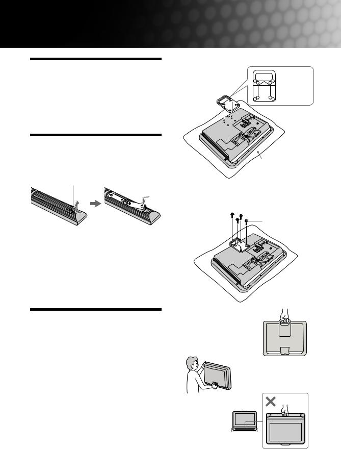
1: Attaching the carrying handle
Attach the carrying handle (supplied) for transportation onto the TV.
Prepare a screwdriver suitable for the screws (supplied) before attaching the carrying handle.
1 Place the TV on a level surface such as the floor with the display panel facing down.
2 Place the carrying handle on the rear of the TV.
Fit the protrusion on the rear of the carrying handle into the guidance holes on the rear of the TV.
The rear side of the carrying handle
 Protrusion
Guidance  hole
hole 

Soft cloth
3 Fix the carrying handle to the TV securely with the four screws (supplied) for the carrying handle.
Screw for the carrying handle
~• When transporting the TV set, hold the carrying handle as shown.
If not using carrying handle, hold the top of the TV and the stand securely.
Do not hold the bottom bar as a handle.
4 GB

2: Connecting an |
3: Preventing the TV |
antenna/cable/VCR |
from toppling over |
Connecting an antenna/cable |
|
8
Antenna cable (not supplied)
Guide up-Start
8 |
Connecting an antenna/cable and VCR
8
8 |
Audio/Video  cable (not supplied)

Antenna cable  (not supplied)
S video  cable
cable
(not
supplied)
Antenna cable (not supplied)
VCR
1 Install a wood screw (4mm in diameter, not supplied) in the TV stand.
2 Install a machine screw (M5 × 12, not supplied) into the screw hole of the TV.
3 Tie the wood screw and the machine screw with a strong cord.
5 GB
4: Bundling the cables
~• The hook of the cable holder can be opened from either sides depending on attaching position.
5: Connecting the AC power cord
6: Performing the initial set-up
 , 1
, 1
BRAVIA Sync 
SYNC MENU |
THEATRE |
|
AUDIO |
|
|
3, 4, 5, 6, 9, |
RETURN |
TOOLS |
10, 11 |
|
|
8 |
Selecting the language
1 Connect the TV to your AC power outlet
(110-240 V AC, 50/60 Hz).
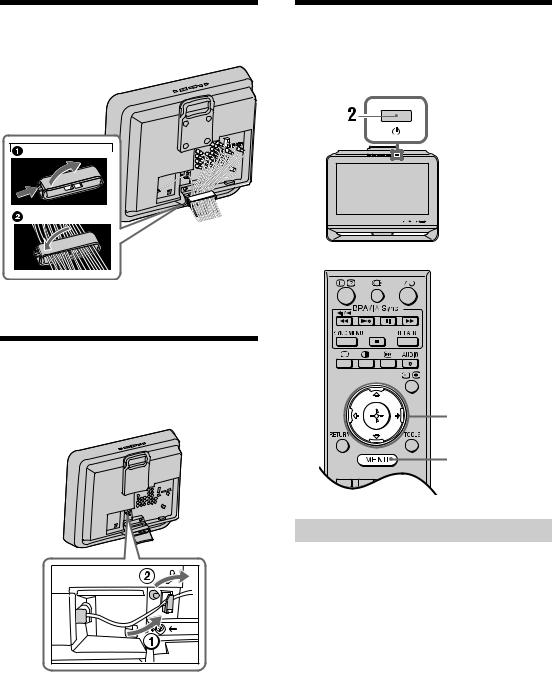
2 Press 1 on the top edge of the TV.
When the TV is in standby mode (the 1 (standby) indicator on the TV front panel is red), press "/1 on the remote to turn on the TV.
When you turn on the TV for the first time, the “Language” menu appears on the screen.
6 GB

3 Press F/f to select the language displayed on the menu screens, then press  .
.
English
4 Press F/f to select the country/region, then press  .
.
~ • Area 1: Asia (except Philippines), Middle East,
Africa and Oceania.
Area 2: Philippines.
5 Press F/f to select “Home”, then press  .
.
Auto-tuning the TV
6 Press G/g to select “OK”, then press  .
.
The TV starts searching for all available channels. This may take some time, please be patient and do not press any buttons on the TV or remote.
If a message appears for you to confirm the antenna connection
No programmes found. Please connect antenna (aerial) and select “Confirm” to start auto-tuning again. If 100 channels are found, auto-tuning is stopped.
7 |
When the “Programme Sorting” menu |
|
|
appears on the screen, follow the steps of |
-Start |
|
“Programme Sorting” (page 30). |
|
|
|
|
|
If you do not change the order in which the channels |
up |
|
are stored on the TV, go to step 8. |
|
8 |
Press MENU to exit. |
Guide |
|
||
|
The TV has now tuned in all the available channels. |
|
9 |
Select day and time. |
|
10 Select “Yes” to link the operations of the TV and the connected equipment that is compatible with control for HDMI automatically.
Do you want to enable control for compatible
HDMI devices?
11 Press G/g to select the desired setting in “Display this menu next time?” dialogue, then press  to exit.
z• If “Yes” is selected and the TV is turned off by pressing 1 on the TV, or is disconnected from the AC power outlet, the initial set-up procedure restarts the next time the TV is turned on.
7 GB

Watching TV
1 Press 1 on the top edge of the TV to turn on the TV.
2 Press the number buttons or PROG +/– to select a TV channel.
3 Press 2 +/– to adjust the volume.
Adjusting the viewing angle of the TV
This TV can be adjusted within the angles shown below.
Adjust the angle back and forth (tilt)
Left view
Front
8 GB
Loading...